2000 MITSUBISHI MONTERO power steering
[x] Cancel search: power steeringPage 219 of 1839

GDI -General Information13A-5
Items Specifications
SensorsAir flow sensorKarman vortex type
Barometric pressure sensorSemiconductor type
Intake air temperature sensorThermistor type
Engine coolant temperature sensorThermistor type
Oxygen sensorZirconia type
Accelerator pedal position sensor (1st
and 2nd channels)Variable resistor type
Accelerator pedal position switchRotary contact type, within accelerator pedal position
sensor (1st channel)
Vehicle speed sensorMagnetic resistive element type
Inhibitor switchContact switch type
Camshaft position sensorHall element type
Crank angle sensorHall element type
Detonation sensorPiezoelectric type
Fuel pressure sensorMetallic membrane type
Power steering fluid pressure switchContact switch type
ActuatorsEngine control relay typeContact switch type
Fuel pump relay typeContact switch type
Injector driver control relayContact switch type
Injector type and numberElectromagnetic type, 6
Injector identification markDIM 1070
Throttle valve control servo relayContact switch type
Throttle valve control servoBrushless DC-motor type
EGR valveStepper motor type
Purge control solenoid valveDuty cycle type solenoid valve
Fuel pressure
regulator (low
pressure)Regulator pressure kPa329
Fuel pressure
regulator
(high pres-
sure)Regulator pressure MPa5.0
www.WorkshopManuals.co.uk
Purchased from www.WorkshopManuals.co.uk
Page 296 of 1839

GDI -Troubleshooting
OK
Check that air is sucked in the air intake system.
DBroken intake manifold gasket
DDamaged vacuum hose
DDamaged air intake hose
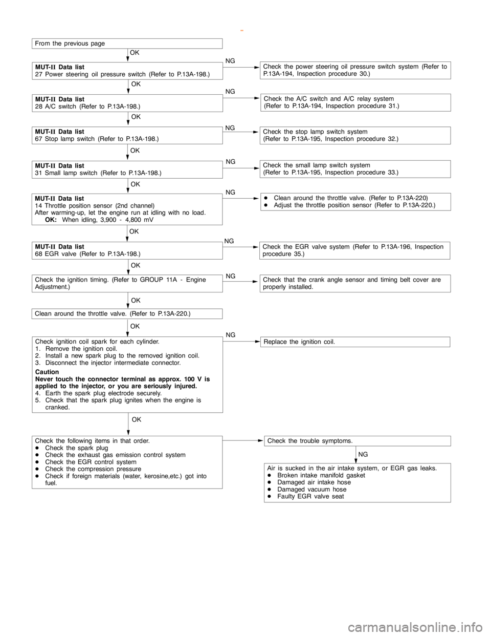
From the previouspage
OK
MUT-
IIData list
27 Power steering fluid pressure switch (Refer to P.13A-105.)NGCheck the power steering fluid pressure switch system. (Refer
to P.13A-102, Inspection procedure 30.)
OK
MUT-
IIData list
28 A/C switch (Refer to P.13A-105.)NGCheck the A/C switch and A/C relay system. (Refer to P.13A-102,
Inspection procedure 31.)
OK
MUT-
IIData list
67 Stoplampswitch (Refer to P.13A-105.)NGCheck the stoplampswitch. (Refer to P.13A-103, Inspection proce-
dure 32.)
OK
MUT-
IIData list
31 Small lampswitch (Refer to P.13A-105.)NGCheck the smalllampswitch system. (Refer to P.13A-104, Inspec-
tion procedure 33.)
OK
MUT-
IIData list
68 EGR valve (Refer to P.13A-105.)NGCheck the EGR valve. (Refer to P.13A-60, code No. P0403.)
OK
NG
Check that the crankanglesensor andtiming beltcover are properly
installed.
OK
Check ignition coil spark for each cylinder.
(1) Remove the ignition coil.
(2) Install a new sparkplug to the removed ignitioncoil.
(3) Disconnect the injector intermediate connector.
Caution
Never touch the connector terminal as approx. 100 V is
applied to the injector, or you are seriously injured.
(4) Earth the sparkplug electrodesecurely.
(5) Check that the sparkplug igniteswhen theengine iscranked.NGReplace the ignition coil.
OK
Check trouble symptom.
Check all the following items in that order.
(1) Spark plugs
(2) Exhaust gas emission control system
(3) EGR system
(4) Compression pressure
(5) Foreign material (such as water or kerosine)entered the fuel
line.
(6) Air is sucked in the air intake system, or EGR gas leaks.
DDamaged intake manifoldgasket
DDamaged air intake hose
DDamaged vacuum hose
DFaulty EGR valve seat
OK
MUT-
IIData list
11 Oxygen sensor (front)
OK:
0 - 400 mV and 600 - 1,000 mV alternates when the
engine is idling(wait for four minutes after theengine
started).NG
NG
Repair
Measure fuel high-pressure between the fuel pump (highpressure)
and injector. (Refer to P.13A-224.)
Clean around the throttle valve. (Refer to P.13A-220.)
NG
Check ignition timing. (Refer to GROUP 11A - Engine Adjustment.)
www.WorkshopManuals.co.uk
Purchased from www.WorkshopManuals.co.uk
Page 300 of 1839

GDI -Troubleshooting
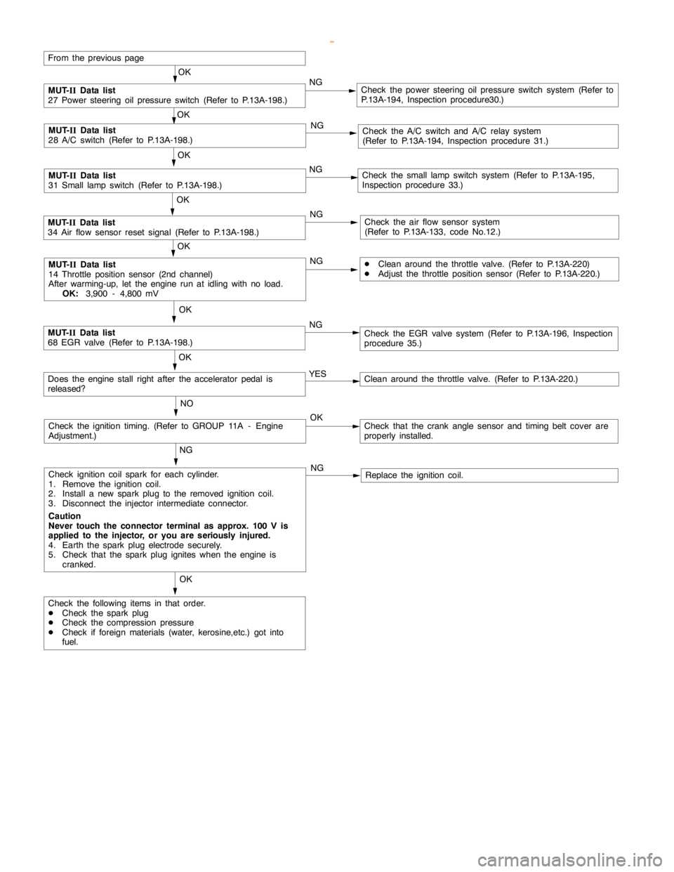
From the previouspage
OK
MUT-
IIData list
27 Power steering fluid pressure switch (Refer to P.13A-105.)NGCheck the power steering fluid pressure switch system. (Refer
to P.13A-102, Inspection procedure 30.)
OK
MUT-
IIData list
28 A/C switch (Refer to P.13A-105.)NGCheck the A/C switch and A/C relay system. (Refer to P.13A-102,
Inspection procedure 31.)
MUT-
IIData list
31 Small lampswitch (Refer to P.13A-105.)NGCheck the smalllampswitch system. (Refer to P.13A-104, Inspec-
tion procedure 33.)
OK
MUT-
IIData list
34 Air flow sensor reset signal (Refer to P.13A-105.)NGCheck the air flow sensor system. (Refer to P.13A-17, code No.
P0100.)
OK
MUT-
IIData list
68 EGR valve (Refer to P.13A-105.)NGCheck the EGR valve. (Refer to P.13A-60, code No. P0403.)
OK
Ye s
Clean around the throttle valve. (Refer to P.13A-220.)
No
NG
Check that the crankanglesensor andtiming beltcover are properly
installed.
OK
Check ignition coil spark for each cylinder.
(1) Remove the ignition coil.
(2) Install a new sparkplug to the removed ignitioncoil.
(3) Disconnect the injector intermediate connector.
Caution
Never touch the connector terminal as approx. 100 V is
applied to the injector, or you are seriously injured.
(4) Earth the sparkplug electrodesecurely.
(5) Check that the sparkplug igniteswhen theengine iscranked.NG
Replace the ignition coil.
OK
Check all the following items:
DSpark plugs
DCompression pressure
DForeign material (such as water or kerosine) entered the fuel
linesOK
Check ignition timing. (Refer to GROUP 11A - Engine Adjustment.)
Does theenginestall immediately after the acceleratorpedal is
released?
www.WorkshopManuals.co.uk
Purchased from www.WorkshopManuals.co.uk
Page 316 of 1839

GDI -Troubleshooting
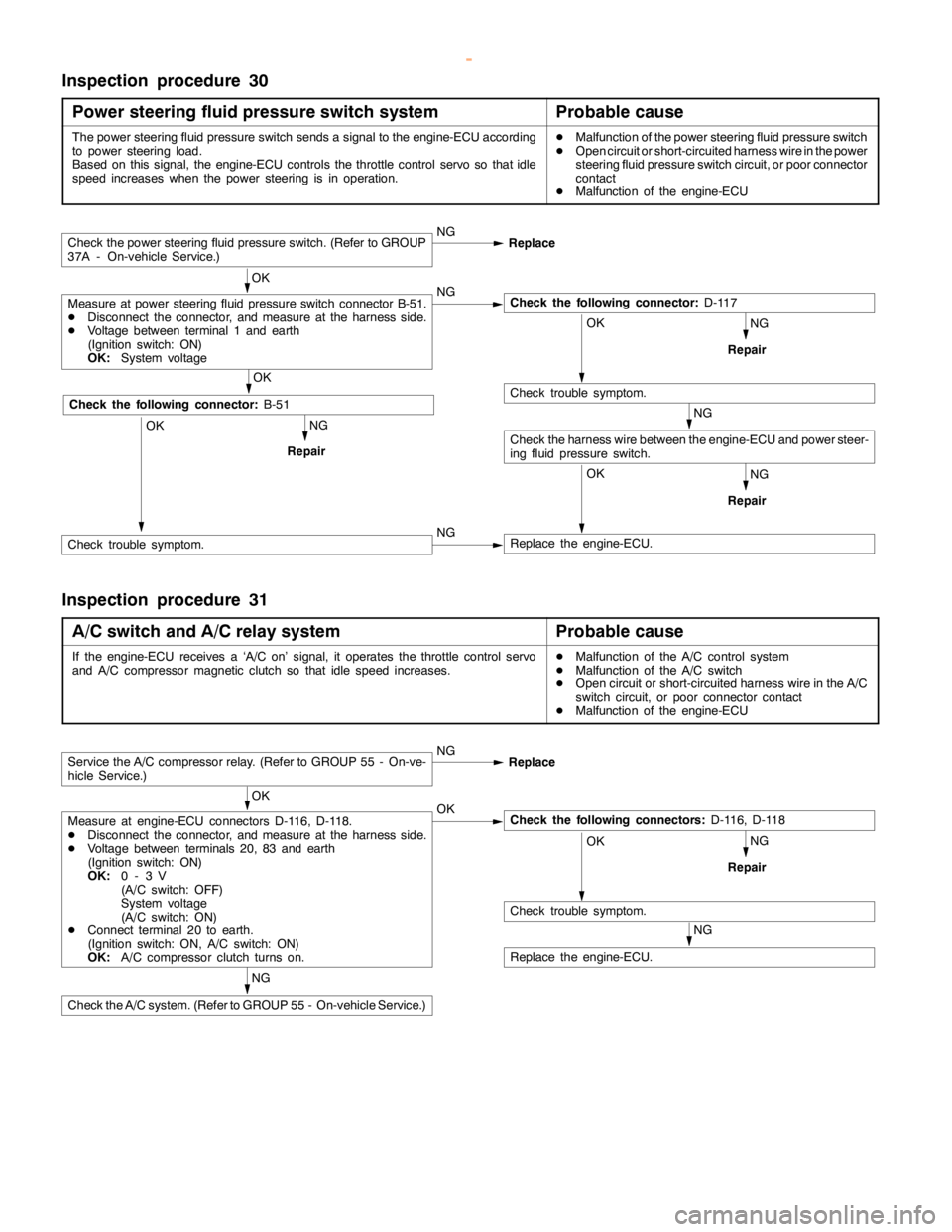
Inspection procedure 30
Power steering fluid pressure switch system
Probable cause
The power steering fluid pressure switch sends a signal to the engine-ECU according
to power steering load.
Based on this signal, the engine-ECU controls the throttle control servo so thatidle
speed increases when the power steering is in operation.DMalfunction of the power steering fluid pressure switch
DOpen circuit or short-circuited harness wire in the power
steering fluid pressure switch circuit, or poor connector
contact
DMalfunction of the engine-ECU
NG
NG
RepairOK
Replace the engine-ECU.
NG
Repair
Check the power steering fluid pressure switch. (Refer to GROUP
37A - On-vehicle Service.)NG
Replace
OK
Measure at power steering fluid pressure switch connector B-51.
DDisconnect the connector, and measure at the harness side.
DVoltage between terminal 1 and earth
(Ignition switch: ON)
OK:
System voltageNGCheck the following connector:
D-117
OK
Check trouble symptom.
Check the harness wire between the engine-ECU and power steer-
ing fluid pressure switch.NG
RepairOK
OK
Check the following connector:
B-51
Check trouble symptom.NG
Inspection procedure 31
A/C switch and A/C relay system
Probable cause
If the engine-ECU receives a ‘A/C on’ signal, it operates the throttle control servo
and A/C compressor magnetic clutch so thatidlespeed increases.DMalfunction of the A/C control system
DMalfunction of the A/C switch
DOpen circuit or short-circuited harness wire in the A/C
switch circuit, or poor connector contact
DMalfunction of the engine-ECU
NG
NG
RepairOK
Check trouble symptom.
NG
Replace the engine-ECU.
Service the A/C compressor relay. (Refer to GROUP 55 - On-ve-
hicle Service.)NG
Replace
OK
Measure at engine-ECU connectors D-116, D-118.
DDisconnect the connector, and measure at the harness side.
DVoltage between terminals 20, 83 and earth
(Ignition switch: ON)
OK:
0-3V
(A/C switch: OFF)
System voltage
(A/C switch: ON)
DConnect terminal 20 to earth.
(Ignition switch: ON, A/C switch: ON)
OK:
A/C compressor clutch turns on.OKCheck the following connectors:
D-116, D-118
Check the A/C system. (Refer to GROUP 55 - On-vehicle Service.)
www.WorkshopManuals.co.uk
Purchased from www.WorkshopManuals.co.uk
Page 321 of 1839

GDI -Troubleshooting
Item
No.Reference
page Inspection
procedure
No. Normal condition Requirements Check items
25BarometricIgnition switch: ONAltitude: 0 m101 kPaCode No.13A-19
pressure sen-
sor
Altitude: 600 m95 kPa
P0105
Altitude: 1,200 m88 kPa
Altitude: 1,800 m81 kPa
26Accelerator
pedal positionIgnition switch: ON
(Depress and re-Release the accel-
erator pedal.ONProcedure
No.2813A-100
switchlease the accelera-
tor pedal several
times)
Depress the accel-
erator pedal slight-
ly.OFF
27Power steer-
ing fluid pres-Engine: IdlingSteering wheel sta-
tionaryOFFProcedure
No.3013A-102
sure switch
Steering wheel
turningON
28A/C switchEngine: Idling (The
A/C compressor isA/C switch: OFFOFFProcedure
No.3113A-100
A/C compressor is
running when the
A/C switch is on.)
A/C switch: ONON
No.31
31Small lamp
switchEngine: IdlingLighting switch:
OFFOFFProcedure
No.3313A-104
Lighting switch: ONON
34Air flow sensorEngine: After hav-Engine is idlingONCode No.13A-17
reset signaling warmed up
3,000 r/minOFF
P0100
37Volumetric effi-
ciencyDEngine coolant
temperature:Engine is idling20 - 40%--
80 - 95_C
DLamps, electric
cooling fan and2,500 r/min10 - 30%
cooling fan and
all accessories:
OFF
DTransmission:
Neutral
Engine is suddenly
racedVolumetric effi-
ciency increases in
response to racing
38Crank angle
sensorDEngine: Cranking [reading is possible
at 2,000 r/min or less]
DTachometer: ConnectedEngine speeds dis-
played on the
MUT-IIand
tachometer are
identical.--
www.WorkshopManuals.co.uk
Purchased from www.WorkshopManuals.co.uk
Page 327 of 1839

GDI -Troubleshooting
Terminal
No.Normal condition Check requirements (engine condition) Check item
47Power supplyIgnition switch: ONSystem voltage
59
50Camshaft position sensorEngine: Cranking0.4 - 3.0 V
Engine: Idling0.5 - 2.0 V
51Barometric pressure sensorIgnition switch:Altitude: 0 m3.7 - 4.3 V
ON
Altitude: 1,200 m3.2 - 3.8 V
52Alternator FR terminalDEngine: Warm up, and then idling
DRadiator fan: not operating
DHeadlamp: OFF®ON
DStop lamp: OFF®ON
DRear defogger: OFF®ONVoltage decreases
53Oxygen sensor (rear)DTransmission: 2nd gear
DEngine speed: 3,500 r/min or more
DDriving with the throttle valve widely
open0.6 - 1.0 V
54Power steering fluid
pressure switchEngine: Warm
up, and thenSteering wheel
stationarySystem voltage
idling
Steering wheel
turning0-3V
55Injector driver relayIgnition switch: OFF0 - 0.1 V
Ignition switch: ON0.5 - 1.0 V
56Throttle valve control servoIgnition switch: OFF0 - 0.3 V
relay
Ignition switch: ON0.5 - 1.0 V
57Engine control relayIgnition switch: OFF0-3V
Ignition switch: ONSystem voltage
60Back-up power sourceIgnition switch: OFFSystem voltage
61Air flow sensorEngine: Idling2.2 - 3.2 V
Engine: 2,500 r/min
62Intake air temperature
sensorIgnition switch:
ONIntake air temper-
ature: 0_C3.2 - 3.8 V
Intake air temper-
ature: 20_C2.3 - 2.9 V
Intake air temper-
ature: 40_C1.5 - 2.1 V
Intake air temper-
ature: 80_C0.4 - 1.0 V
www.WorkshopManuals.co.uk
Purchased from www.WorkshopManuals.co.uk
Page 389 of 1839

Page 393 of 1839
