Page 46 of 1839

3 MSB-00E00-505
3. Details:
Contents of Attachment are to be added to GROUP 00 (GENERAL).
PRECAUTIONS BEFORE SERVICE
LEARNING FUNCTION OF GDI ENGINE
1. Purpose
On the GDI engine equipped cars, when replacement of the ECU (for engine control) or resetting
of the battery* has been performed, an idle learning function of the ECU (for engine control) will
be required.
The idle learning function will be completed by running the engine at idle by the following procedure.
NOTE:
*: Disconnection of ECU (for engine control) battery backup power supply (disconnection of battery
terminals or ECU connectors)
2. Idle Learning Procedure
(1) Start the engine, and warm up the engine until its coolant temperature reaches 85°C or higher.
When the engine coolant temperature is 85°C or higher, you have only to turn the ignition
switch to the ON position.
(2) Turn the ignition switch to the LOCK (OFF) position, and stop the engine.
(3) After lapse of ten or more seconds, restart the engine.
(4) Run the engine at idle for ten minutes under the following conditions.
DTransmission: Neutral (P range for automatic transmission)
DAir conditioner and heater: Not operational
DEngine coolant temperature: 83°C or higher
(5) Stop the engine.
(6) Restart the engine, and run it at idle for ten minutes under the following condition.
DTransmission: Neutral (P range for automatic transmission)
DAir conditioner: Operational (Temperature set at “maximum cool”, fan at high speed, and
windows fully opened)
DEngine coolant temperature: 83°C or higher
(7) Repeat steps (5) and (6).
NOTE:
1) When the atmospheric temperature is 20°C or more and the air conditioner has continuously
been operated, step (7) may be omitted.
2) During idling operation of the engine in steps (4) and (6), when engine operation switches
from lean operation to stoichiometric operation, engine stall can occur. In this case, clean the
throttle body (throttle valve) thoroughly, and then repeat step (1) and the subsequent steps.
www.WorkshopManuals.co.uk
Purchased from www.WorkshopManuals.co.uk
Page 1624 of 1839

CHASSIS ELECTRICAL -Clock or Center Display54A-54
BEFORE REMOVING THE BATTERY
The Center display has a large amount of data unique to the vehicle in its memory. When the battery
cable is disconnected, that memory is affected as shown in the table below. Accordingly, it is necessary
to make sure that you take notes of important information before disconnecting the battery cable.
FunctionInput function/memoryWhen battery cable is disconnected
Clock set on displayCurrent timeRetains data for approx. 1 hour
Vehicle model setShort (3-door models)/long (5-door
models)Retains data for approx. 1 hour
Brightness set for displayPosition set on displayRetains data for approx. 1 hour
Unit set for trip computerkm or mile, L/100km or mpg or km/L
Average vehicle speed after resetRetains data for approx. 1 hour
Average vehicle speed on displayAverage vehicle speed after resetRetains data for approx. 1 hour
Average fuel consumption on displayAverage fuel consumption after resetRetains data for approx. 1 hour
Cruising range on displayCruising range, fuel economyRetains data for approx. 1 hour
Outside temperature on displayOutside temperature after the ignition
switch is turned to the OFF(LOCK)
position.Retains data for approx. 1 hour
* The outside temperature sensor
is located near the engine.
Therefore, incorrectly high
temperature may be displayed
when the battery cable is
reconnected within one hour.
DIAGNOSIS FUNCTION FOR CENTER DISPLAY
Center display has the following diagnosis function:
FunctionContents
Service functionThere are the following 4 diagnosis modes available
1. Check of vehicle informationThe vehicle, short (3-door models)/long (5-door models) set
2. Check of LCD segmentsThe LCD segments for display available to light on or not
3. Check of sensorsOutside temperature, voltage of fuel gauge unit, system voltage, fuel amount
remains, fuel economy calculated after supply of fuel
4. Check of units connected into
the center displayThe units connected on display
Voltage (%) on terminal for MUT-II
Vehicle speed signal sent by engine-ECU
Oscillating signal
www.WorkshopManuals.co.uk
Purchased from www.WorkshopManuals.co.uk
Page 1647 of 1839

CHASSIS ELECTRICAL -Radio/Tape Player54A-77
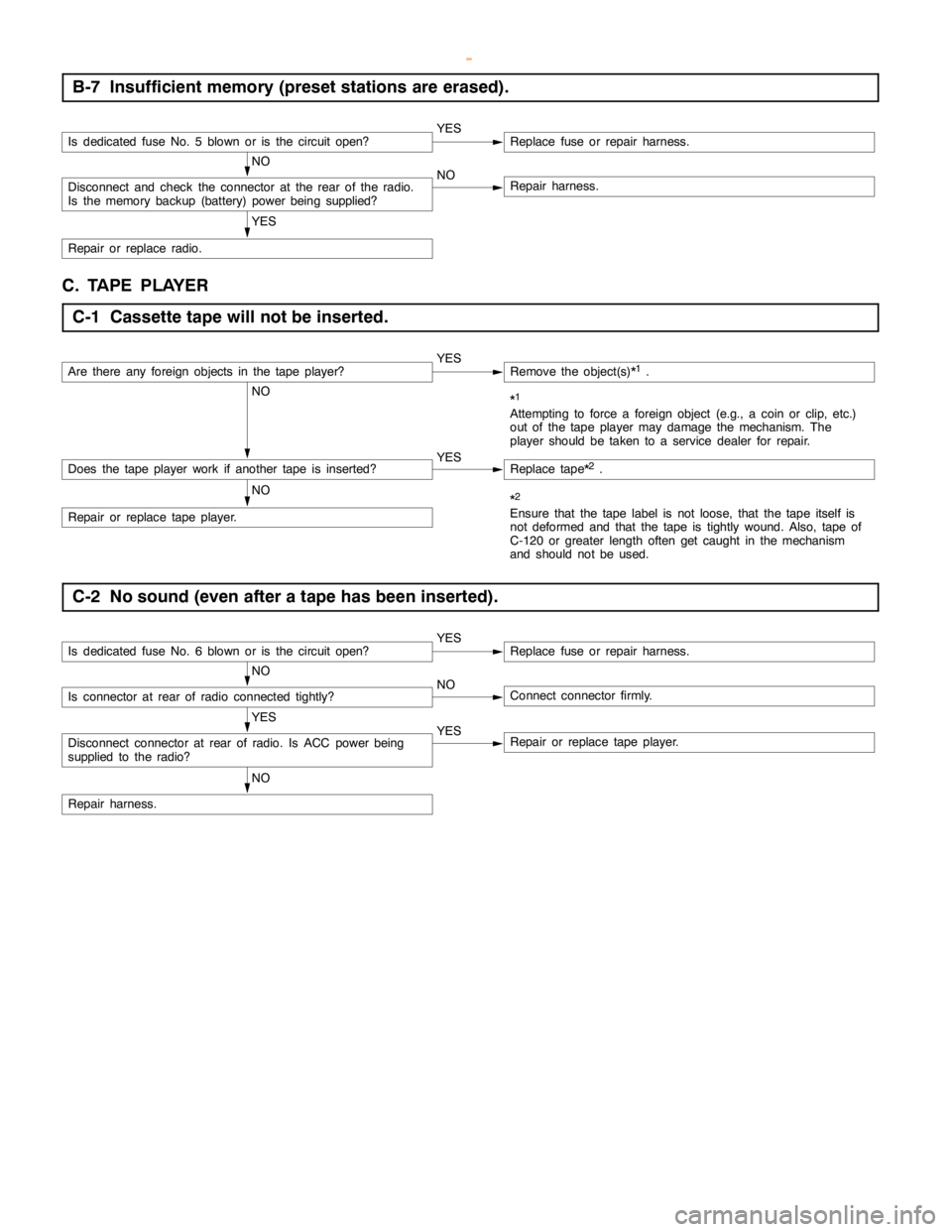
B-7 Insufficient memory (preset stations are erased).
Is dedicated fuse No. 5 blown or is the circuitopen?YESReplace fuse or repair harness.
NO
Disconnect and check the connector at the rear of the radio.
Is the memory backup (battery) powerbeing supplied?NORepair harness.
YES
Repair or replace radio.
C. TAPE PLAYER
C-1 Cassette tape will not be inserted.
Are there any foreign objects in the tape player?YESRemove the object(s)*1.
NO*1
Attempting to force a foreign object (e.g., a coin or clip, etc.)
out of the tape player maydamage the mechanism. The
player should be taken to a service dealer for repair.
Does the tape player work if another tape is inserted?YESReplace tape*2.
NO
Repair or replace tape player.
*2
Ensure that the tape label is not loose, that the tape itself is
not deformed and that the tape is tightly wound. Also, tape of
C-120 or greater length often get caught in the mechanism
and should not be used.
C-2 No sound (even after a tape has been inserted).
Is dedicated fuse No. 6 blown or is the circuitopen?YESReplace fuse or repair harness.
NO
Is connector at rear of radio connected tightly?NOConnect connector firmly.
YES
Disconnect connector at rear of radio. Is ACC powerbeing
supplied to the radio?YESRepair or replace tape player.
NO
Repair harness.
www.WorkshopManuals.co.uk
Purchased from www.WorkshopManuals.co.uk