Page 1221 of 1839
BASIC BRAKE SYSTEM -Troubleshooting35A-13
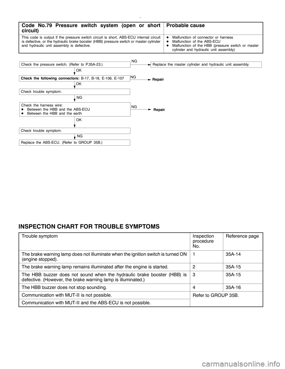
Code No.79 Pressure switch system (open or short
circuit)Probable cause
This code is output if the pressure switch circuit is short, ABS-ECU internal circuit
is defective, or the hydraulic brake booster (HBB) pressure switch or master cylinder
and hydraulic unit assembly is defective.DMalfunction of connector or harness
DMalfunction of the ABS-ECU
DMalfunction of the HBB (pressure switch or master
cylinder and hydraulic unit assembly)
NG
Repair
NG
OKRepair NG
OK
Check trouble symptom.
Check the following connectors:
B-17, B-18, E-106, E-107
Check the harness wire:
DBetween the HBB and the ABS-ECU
DBetween the HBB and the earthNG
Check trouble symptom.
Replace the ABS-ECU. (Refer to GROUP 35B.)
NG
OKCheck the pressure switch. (Refer to P.35A-23.)Replace the master cylinder and hydraulic unit assembly.
INSPECTION CHART FOR TROUBLE SYMPTOMS
Trouble symptomInspection
procedure
No.Reference page
The brake warning lamp does not illuminate when the ignition switch is turned ON
(engine stopped).135A-14
The brake warning lamp remains illuminated after the engine is started.235A-15
The HBB buzzer does not sound when the hydraulic brake booster (HBB) is
defective. (However, the brake warning lamp is illuminated.)335A-15
The HBB buzzer does not stop sounding.435A-16
Communication with MUT-II
is not possible.Refer to GROUP 35B.
Communication with MUT-II
and the ABS-ECU is not possible.
www.WorkshopManuals.co.uk
Purchased from www.WorkshopManuals.co.uk
Page 1222 of 1839
BASIC BRAKE SYSTEM -Troubleshooting35A-14
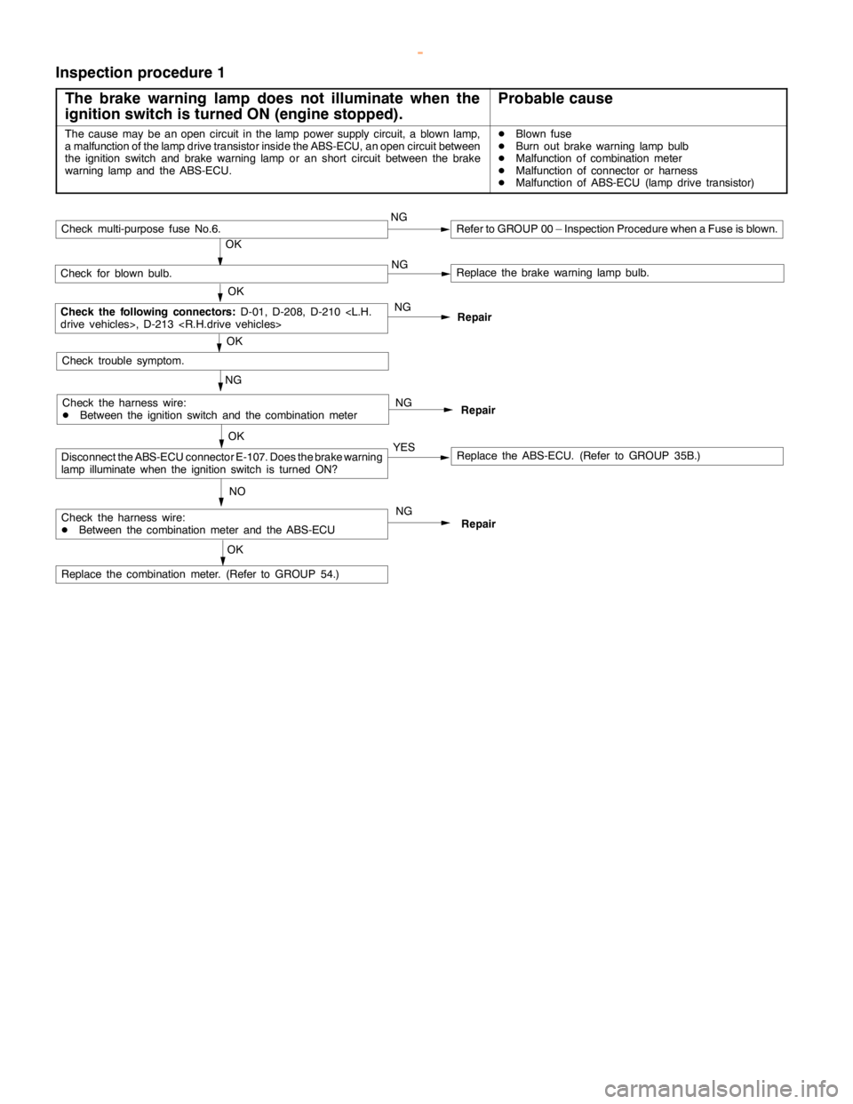
Inspection procedure 1
The brake warning lamp does not illuminate when the
ignition switch is turned ON (engine stopped).
Probable cause
The cause may be anopencircuit in thelamppower supply circuit, a blown lamp,
a malfunction of the lampdrive transistor inside the ABS-ECU, anopencircuit between
the ignition switch and brake warninglamp or anshort circuit between the brake
warning lamp and theABS-ECU.DBlown fuse
DBurn out brake warninglamp bulb
DMalfunction of combination meter
DMalfunction of connector or harness
DMalfunction of ABS-ECU (lamp drive transistor)
Repair NG NG
NO
Replace the ABS-ECU. (Refer to GROUP 35B.)
Repair
Repair
NG
OK
Check for blown bulb.Replace the brake warninglamp bulb.
OK
Check the following connectors:
D-01, D-208, D-210
drive vehicles>, D-213
NG
Replace the combination meter. (Refer to GROUP 54.)
OK
Check trouble symptom.
OK
YES
Check multi-purpose fuse No.6.NGRefer to GROUP 00 – Inspection Procedure when a Fuse is blown.
Check the harness wire:
DBetween the ignition switch and the combination meter
Check the harness wire:
DBetween the combination meter and the ABS-ECU
Disconnect the ABS-ECU connector E-107. Does the brake warning
lamp illuminatewhen the ignition switch is turned ON?
NG
OK
www.WorkshopManuals.co.uk
Purchased from www.WorkshopManuals.co.uk
Page 1223 of 1839
BASIC BRAKE SYSTEM -Troubleshooting35A-15
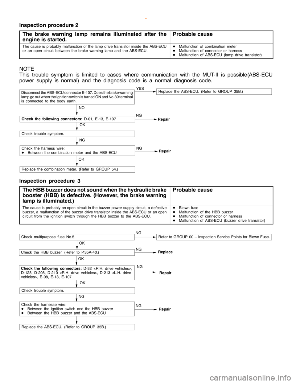
Inspection procedure 2
The brake warning lamp remains illuminated after the
engine is started.
Probable cause
The cause is probably malfunction of thelampdrive transistor inside the ABS-ECU
or an opencircuit between the brake warninglamp and theABS-ECU.DMalfunction of combination meter
DMalfunction of connector or harness
DMalfunction of ABS-ECU (lamp drive transistor)
NOTE
This trouble symptom is limited to cases where communication with the MUT-II is possible(ABS-ECU
power supply is normal) and the diagnosis code is a normal diagnosis code.
Repair NG
Repair
Replace the combination meter. (Refer to GROUP 54.)
OK
YESReplace the ABS-ECU. (Refer to GROUP 35B.)
NO
Disconnect the ABS-ECU connector E-107. Does the brake warning
lamp go outwhen the ignition switch is turned ON and No.39 terminal
is connected to the body earth.
OK
Check the following connectors:
D-01, E-13, E-107
Check trouble symptom.
Check the harness wire:
DBetween the combination meter and the ABS-ECUNG
NG
Inspection procedure 3
The HBB buzzer does not sound when the hydraulic brake
booster (HBB) is defective. (However, thebrake warning
lamp is illuminated.)
Probable cause
The cause is probably anopencircuit in the buzzer power supply circuit, a defective
buzzer, a malfunction of the buzzer drive transistor inside the ABS-ECU or anopen
circuit from the ignition switch through the HBB buzzer to the ABS-ECU.DBlown fuse
DMalfunction of the HBB buzzer
DMalfunction of connector or harness
DMalfunction of ABS-ECU (buzzer drive transistor)
Replace the ABS-ECU. (Refer to GROUP 35B.)
Repair NG
Repair
NG
OK
Check the HBB buzzer. (Refer to P.35A-40.)
OK
Check the following connectors:
D-32 ,
D-128, D-208, D-210 , D-213
vehicles>, E-08, E-13, E-107
NG
OK
Check trouble symptom.
Check multipurpose fuse No.5.NGRefer to GROUP 00 – Inspection Service Points for Blown Fuse.
Check the harnesse wire:
DBetween the ignition switch and the HBB buzzer
DBetween the HBB buzzer and the ABS-ECUNGReplace
www.WorkshopManuals.co.uk
Purchased from www.WorkshopManuals.co.uk
Page 1224 of 1839
BASIC BRAKE SYSTEM -Troubleshooting35A-16
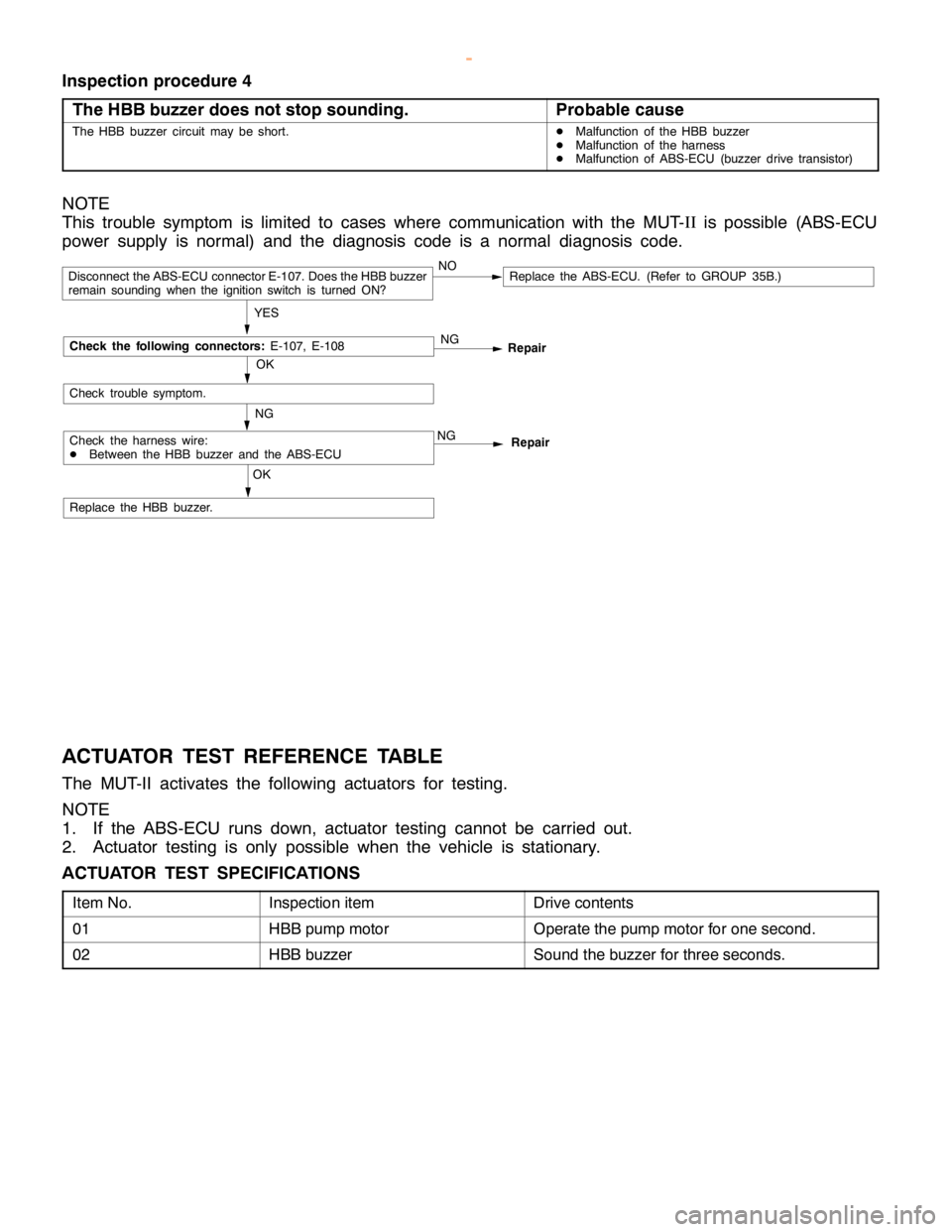
Inspection procedure 4
The HBB buzzer does not stop sounding.
Probable cause
The HBB buzzer circuit may be short.DMalfunction of the HBB buzzer
DMalfunction of the harness
DMalfunction of ABS-ECU (buzzer drive transistor)
NOTE
This trouble symptom is limited to cases where communication with the MUT-II
is possible (ABS-ECU
power supply is normal) and the diagnosis code is a normal diagnosis code.
OK
Repair NG
Repair
Replace the HBB buzzer.
OK
NG
YES
Replace the ABS-ECU. (Refer to GROUP 35B.)NODisconnect the ABS-ECU connector E-107. Does the HBB buzzer
remain sounding when the ignition switch is turned ON?
Check trouble symptom.
Check the harness wire:
DBetween the HBB buzzer and the ABS-ECUNG
Check the following connectors:
E-107, E-108
ACTUATOR TEST REFERENCE TABLE
The MUT-II activates the following actuators for testing.
NOTE
1. If the ABS-ECU runs down, actuator testing cannot be carried out.
2. Actuator testing is only possible when the vehicle is stationary.
ACTUATOR TEST SPECIFICATIONS
Item No.Inspection itemDrive contents
01HBB pump motorOperate the pump motor for one second.
02HBB buzzerSound the buzzer for three seconds.
www.WorkshopManuals.co.uk
Purchased from www.WorkshopManuals.co.uk
Page 1235 of 1839
BASIC BRAKE SYSTEM -On-vehicle ServiceBASIC BRAKE SYSTEM -On-vehicle Service35A-27
BLEEDING
Caution
Specified brake fluid: DOT3 or DOT4
1. Always use the specified brake fluid. Avoid using
a mixture of the specified brake fluid and other fluid.
2. Maintain the fluid reservoir level between the MIN
and MAX marks during the air bleeding.
3. Do not depress the brake pedal hard during the air
bleeding (normal air bleeding) to prevent the pump
motor from operating frequently.
4. After the air bleeding, check that the brake dragging
does not become stronger.
5. If the pedal is depressed with the reservoir cap
removed, the brake fluid may overflow. Do not depress
the brake pedal while the fluid is being added.
NORMAL AIR BLEEDING
After the front brake or the rear brake is removed and installed,
some fluid may remain in the hydraulic brake booster (HBB)
reservoir. In this case, bleed air from the brake caliper.
HBB SYSTEM AIR BLEEDING
If all the brake fluid inside the reservoir is drained due to
the removal and installation of the HBB, bleed air as follows:
Air bleeding from front brake system
1. Turn the ignition switch to the LOCK (OFF) position. Bleed
air from the front brake calipers (right and left) by pumping
the brake pedal.
Pump motor operation
2. Turn the ignition switch ON, and operate the pump motor.
If the pump motor is running free, supply the brake fluid
into the pump motor by depressing the brake pedal three
or four times.
Air bleeding from accumulator system
3. After the pump motor stopped, depress the brake pedal
three or four times with the ignition switch ON. Then
observe the brake fluid in the reservoir. If the brake fluid
looks whitish, wait for a few minutes until it becomes
clear.
4. Repeat step 3 until the brake fluid becomes clear.
www.WorkshopManuals.co.uk
Purchased from www.WorkshopManuals.co.uk
Page 1238 of 1839
M
IN
M
AX
MIN
V
eh ic le s wit h ABS
V eh ic le s wit h out ABS
Page 1244 of 1839
H
YD RAULIC BRAKE BO OSTE R (H BB)
R EM OVA L AND IN STA LLA TIO N
C au tio n
D o not tu rn th e ig nit io n sw it c h ON befo re th e bra ke flu id has been re fille d to pre ven t th e HBB
p um p moto r fr o m dam ag e. 2
7
Page 1248 of 1839
H
BB BUZZE R
R EM OVA L AND IN STA LLA TIO N


