2000 MITSUBISHI MONTERO window
[x] Cancel search: windowPage 46 of 1839

3 MSB-00E00-505
3. Details:
Contents of Attachment are to be added to GROUP 00 (GENERAL).
PRECAUTIONS BEFORE SERVICE
LEARNING FUNCTION OF GDI ENGINE
1. Purpose
On the GDI engine equipped cars, when replacement of the ECU (for engine control) or resetting
of the battery* has been performed, an idle learning function of the ECU (for engine control) will
be required.
The idle learning function will be completed by running the engine at idle by the following procedure.
NOTE:
*: Disconnection of ECU (for engine control) battery backup power supply (disconnection of battery
terminals or ECU connectors)
2. Idle Learning Procedure
(1) Start the engine, and warm up the engine until its coolant temperature reaches 85°C or higher.
When the engine coolant temperature is 85°C or higher, you have only to turn the ignition
switch to the ON position.
(2) Turn the ignition switch to the LOCK (OFF) position, and stop the engine.
(3) After lapse of ten or more seconds, restart the engine.
(4) Run the engine at idle for ten minutes under the following conditions.
DTransmission: Neutral (P range for automatic transmission)
DAir conditioner and heater: Not operational
DEngine coolant temperature: 83°C or higher
(5) Stop the engine.
(6) Restart the engine, and run it at idle for ten minutes under the following condition.
DTransmission: Neutral (P range for automatic transmission)
DAir conditioner: Operational (Temperature set at “maximum cool”, fan at high speed, and
windows fully opened)
DEngine coolant temperature: 83°C or higher
(7) Repeat steps (5) and (6).
NOTE:
1) When the atmospheric temperature is 20°C or more and the air conditioner has continuously
been operated, step (7) may be omitted.
2) During idling operation of the engine in steps (4) and (6), when engine operation switches
from lean operation to stoichiometric operation, engine stall can occur. In this case, clean the
throttle body (throttle valve) thoroughly, and then repeat step (1) and the subsequent steps.
www.WorkshopManuals.co.uk
Purchased from www.WorkshopManuals.co.uk
Page 1353 of 1839

42-1
BODY
CONTENTS
HOOD3 ....................................
FENDER5 ..................................
FUEL FILLER DOOR6 .....................
WINDOW GLASS8 .........................
ADHESIVES 8.............................
SPECIAL TOOL 8.........................
WINDOW REPAIR 8.......................
WINDSHIELD 10..........................
QUARTER WINDOW GLASS 14...........
BACK DOOR GLASS 16..................
DOORS18 .................................
SERVICE SPECIFICATIONS 18............
SEALANT 18.............................
SPECIAL TOOLS 18......................
TROUBLESHOOTING 19..................ON-VEHICLE SERVICE 19................
Door Fit Adjustment 19.................
Door Window Glass Adjustment 19......
Defective Power Window Adjustment and
Replacement
20 .........................
Power Window Safety Mechanism Check 20..
Door Outside Handle Play Check 21.....
Power Window Operation Current
Check 21..............................
Circuit Breaker (Incorporated in the Power
Window Motor) Check 21...............
Door Inside Handle Play Check and
Adjustment 21..........................
DOOR ASSEMBLY 22.....................
DOOR TRIM AND WATERPROOF
FILM 24..................................
DOOR GLASS AND REGULATOR 30......
DOOR HANDLE AND LATCH 33..........
WINDOW GLASS RUNCHANNEL AND
DOOR OPENING WEATHERSTRIP 36.....
BACK DOOR39 ...........................
SERVICE SPECIFICATION 39.............
SEALANT 39.............................
SPECIAL TOOL 39.......................
TROUBLESHOOTING 39..................
CONTINUED ON NEXT PAGE
www.WorkshopManuals.co.uk
Purchased from www.WorkshopManuals.co.uk
Page 1361 of 1839

BODY -Window Glass42-9
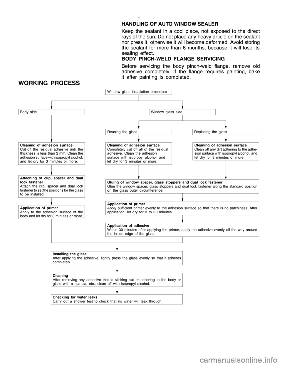
HANDLING OF AUTO WINDOW SEALER
Keep the sealant in a cool place, not exposed to the direct
rays of the sun. Do not place any heavy article on the sealant
nor press it, otherwise it will become deformed. Avoid storing
the sealant for more than 6 months, because it will lose its
sealing effect.
BODY PINCH-WELD FLANGE SERVICING
Before servicing the body pinch-weld flange, remove old
adhesive completely. If the flange requires painting, bake
it after painting is completed.
WORKING PROCESS
Window glass installation procedure
Body side
Cleaning of adhesion surface
Cut off the residual adhesive until the
thickness is less than 2 mm. Clean the
adhesion surface with isopropyl alcohol,
and let dry for 3 minutes or more.
Attaching of clip, spacer and dual
lock fastener
Attach the clip, spacer andduallock
fastener to set the positions for the glass
to be installed.
Application of primer
Apply to the adhesion surface of the
body and let dry for 3 minutes or more.
Window glass side
Reusing the glassReplacing the glass
Cleaning of adhesion surface
Completely cut off all of the residual
adhesive. Clean the adhesion
surface with isopropyl alcohol, and
let dry for 3 minutes or more.Cleaning of adhesion surface
Clean off any dirt adhering to the adhe-
sion surface with isopropyl alcohol, and
let dry for 3 minutes or more.
Gluing of window spacer, glass stoppers and dual lock fastener
Glue the window spacer, glass stoppers andduallock fasteneralong the standard position
on the glass outer circumference.
Application of primer
Apply sufficient primer evenly to the adhesion surface so that there is no patchiness. After
application, let dry for 3 to 30 minutes.
Application of adhesive
Within 30 minutes after applying the primer, apply the adhesive evenly all the way around
the inside edge of theglass.
Installing the glass
After applying the adhesive, lightly press the glass evenly so that it adheres
completely.
Cleaning
After removing any adhesive that is sticking out or adhering to the body or
glass with a spatula, etc., clean off with isopropyl alcohol.
Checking for water leaks
Carry out a shower test to check that no water will leak through.
www.WorkshopManuals.co.uk
Purchased from www.WorkshopManuals.co.uk
Page 1573 of 1839

54A-3
ON-VEHICLE SERVICE 46......................
Room Lamp Delay-off Time Adjustment
Procedure 46...............................
REAR COMBINATION LAMP 47...........
SPECIAL TOOLS 47...........................
TROUBLESHOOTING 47.......................
REAR COMBINATION LAMP 47................
HIGH-MOUNTED STOP LAMP 48.........
COLUMN SWITCH 48....................
SPECIAL TOOLS 48...........................
COLUMN SWITCH 48..........................
HAZARD WARNING LAMP SWITCH 50....
SPECIAL TOOLS 50...........................
HAZARD WARNING LAMP SWITCH 50.........
HORN 51................................
CIGARETTE LIGHTER 51.................
ACCESSORY SOCKET 51................
RHEOSTAT 52...........................
CLOCK OR CENTER DISPLAY 53........
TROUBLESHOOTING 53.......................
CLOCK OR CENTER DISPLAY 67..............
RADIO/TAPE PLAYER 68.................
TROUBLESHOOTING 68.......................
RADIO AND CD AUTO CHANGER 81..........
FRONT SPEAKERS 82...................
REAR SPEAKERS 82.....................
ANTENNA83 ............................DEFOGGER 86...........................
TROUBLESHOOTING
ON-VEHICLE SERVICE 86.....................
Printed Heater Check 86.....................
Defogger Relay Continuity Check 86...........
DEFOGGER SWITCH 87.......................
SMART WIRING SYSTEM (SWS)
Refer to GROUP 54B ....................
RADIATOR (RADIATOR FAN MOTOR)
Refer to GROUP 14 ......................
AUTOMATIC TRANSMISSION
Refer to GROUP 23 ......................
ANTI-LOCK BRAKE SYSTEM (ABS)
Refer to GROUP 35B ....................
DOOR HANDLE LATCH (DOOR LOCK)
Refer to GROUP 42 ......................
DOOR GLASS-REGULATOR (POWER
WINDOWS)
Refer to GROUP 42 ......................
KEYLESS ENTRY SYSTEM
Refer to GROUP 42 ......................
WINDSHIELD WIPER/WASHER
Refer to GROUP 51 ......................
REAR WIPER/WASHER
Refer to GROUP 51 ......................
SRS AIRBAG Refer to GROUP 52B......
HEATER Refer to GROUP 55.............
AIR CONDITIONER Refer to GROUP 55...
www.WorkshopManuals.co.uk
Purchased from www.WorkshopManuals.co.uk
Page 1688 of 1839

SWS -General InformationSWS -General Information54B-2
GENERAL INFORMATION
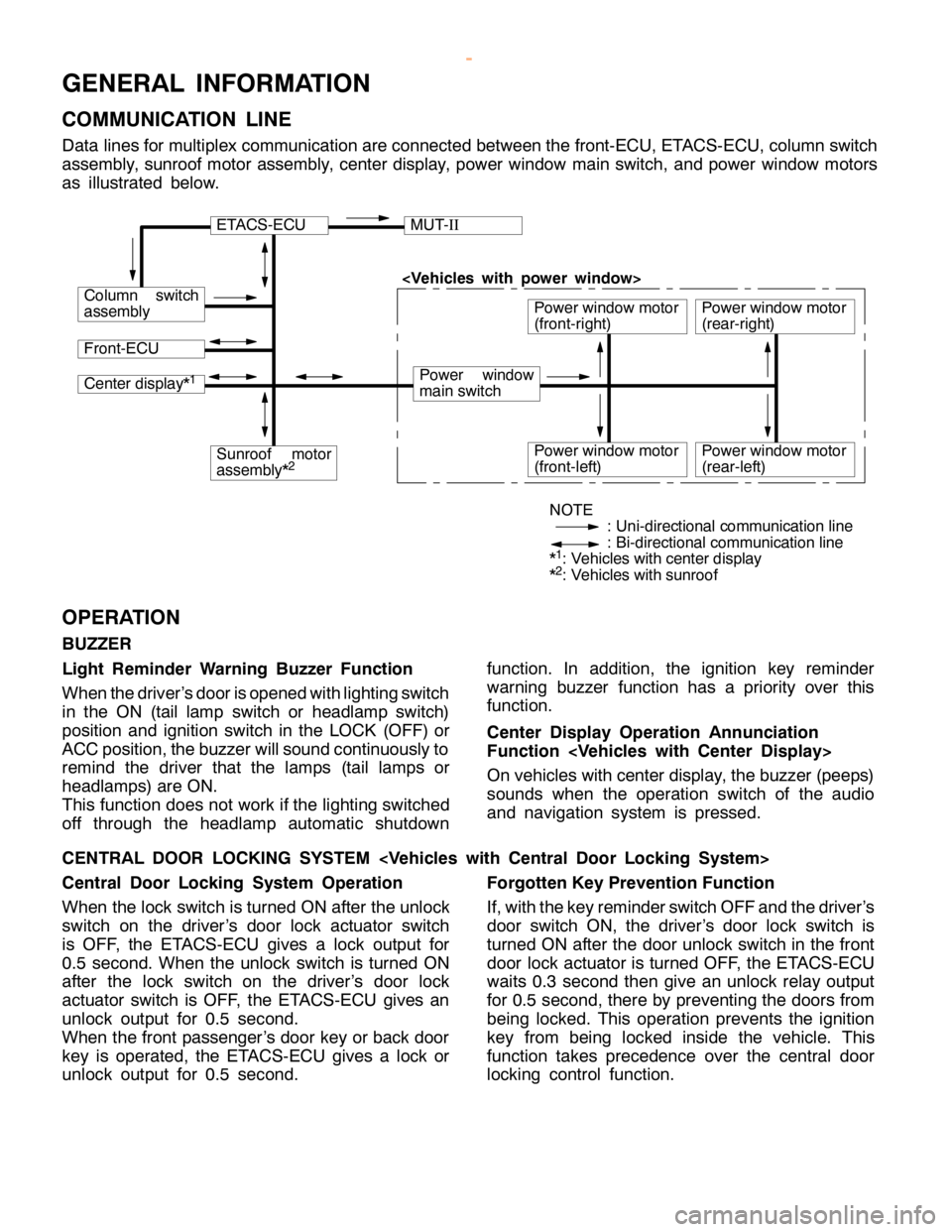
COMMUNICATION LINE
Data lines for multiplex communication are connected between the front-ECU, ETACS-ECU, column switch
assembly, sunroof motor assembly, center display, power window main switch, and power window motors
as illustrated below.
ETACS-ECUMUT-II
Column switch
assembly
Front-ECU
Power window
main switch
Power window motor
(front-right)
Center display*1
Sunroof motor
assembly*2Power window motor
(front-left)
Power window motor
(rear-right)
Power window motor
(rear-left)
NOTE
: Uni-directional communication line
: Bi-directional communication line
*
1: Vehicles with center display
*2: Vehicles with sunroof
OPERATION
BUZZER
Light Reminder Warning Buzzer Function
When the driver’s door is opened with lighting switch
in the ON (tail lamp switch or headlamp switch)
position and ignition switch in the LOCK (OFF) or
ACC position, the buzzer will sound continuously to
remind the driver that the lamps (tail lamps or
headlamps) are ON.
This function does not work if the lighting switched
off through the headlamp automatic shutdownfunction. In addition, the ignition key reminder
warning buzzer function has a priority over this
function.
Center Display Operation Annunciation
Function
On vehicles with center display, the buzzer (peeps)
sounds when the operation switch of the audio
and navigation system is pressed.
CENTRAL DOOR LOCKING SYSTEM
Central Door Locking System Operation
When the lock switch is turned ON after the unlock
switch on the driver’s door lock actuator switch
is OFF, the ETACS-ECU gives a lock output for
0.5 second. When the unlock switch is turned ON
after the lock switch on the driver’s door lock
actuator switch is OFF, the ETACS-ECU gives an
unlock output for 0.5 second.
When the front passenger’s door key or back door
key is operated, the ETACS-ECU gives a lock or
unlock output for 0.5 second.Forgotten Key Prevention Function
If, with the key reminder switch OFF and the driver’s
door switch ON, the driver’s door lock switch is
turned ON after the door unlock switch in the front
door lock actuator is turned OFF, the ETACS-ECU
waits 0.3 second then give an unlock relay output
for 0.5 second, there by preventing the doors from
being locked. This operation prevents the ignition
key from being locked inside the vehicle. This
function takes precedence over the central door
locking control function.
www.WorkshopManuals.co.uk
Purchased from www.WorkshopManuals.co.uk
Page 1689 of 1839

SWS -General Information54B-3
POWER WINDOWS
Power Windows Operation
A signal line dedicated for transmission of multiplex
communication data is connected between the
power window main switches and the power window
motor-ECU.
Communication is uni-directional. The power
window main switches have a transmitting circuit
only, whereas the power window sub switches have
a receiving circuit only.
Power Window Timer Function
With the ignition switch in the ON position, the power
window relay and power window switch receipt
permission signal (a SWS signal transmitted from
the ETACS-ECU) are turned ON [the power windowswitch receipt permission signal remains ON for 30
seconds after the ignition switch is turned LOCK
(OFF)], enabling opening and closing of the
windows. The power window relay goes ON for
additional 30 seconds. If the driver’s door is
subsequently closed during this period, the receipt
permission signal goes OFF. The power window
relay goes OFF 10 seconds after the receipt
permission signal goes OFF.
If the driver’s door is opened during timer operation,
the receipt permission signal goes ON for additional
30 seconds. If the driver’s door is subsequently
closed during this period, the receipt permission
signal goes OFF ten seconds after the receipt
permission signal goes OFF.
KEYLESS ENTRY SYSTEM
Keyless Entry System Operation
If the transmitter LOCK or UNLOCK switch is
pressed while the ignition key is removed and all
of the doors are closed, the doors can be locked
or unlocked.
Keyless Entry Answerback Function
The keyless entry hazard answerable function
facilitates confirmation of door locking and unlock-
ing operations even in daylight. When a LOCKsignal from the keyless entry transmitter is applied
to the ETACS-ECU, all of the turn-signal lamps flash
twice. When an UNLOCK signal from the keyless
entry transmitter is applied to the ETACS-ECU, all of
the turn-signal lamps flash four times. Note that an
unlock switch has change from OFF to ON.
NOTE
The hazard answer back is enabled or disabled
by the configuration function.
SUNROOF
Sunroof Operation
All of the slide open/close, tilt up/down, and stop
operations can be performed by a single switch.
When the roof lid glass is tilted up, the sunshade
opens approximately 98 mm in combined operation
with the roof lid glass for better ventilation.
A jam preventing mechanism has been adopted.
When a slide-close or tilt-down operation is blocked
by an external force, the roof lid glass moves back
and stops.Sunroof Timer Function
When the ignition switch is turned from ON position
to LOCK (OFF) or ACC position, the sunroof will
be ready to work for 30 seconds.
If the driver’s door is opened during the timer
operation, the timer operates for another
30
seconds starting from that point. However, the
timer operation discontinues if the door is closed
during that period.
www.WorkshopManuals.co.uk
Purchased from www.WorkshopManuals.co.uk
Page 1695 of 1839

SWS -Troubleshooting54B-9
Input signalBuzzer operation condition
Column switchTail lamp switchTurned the lighting switch from OFF to tail lamp
position
Headlamp switchTurn the lighting switch from tail lamp position to
headlamp position
Dimmer switchTurned from OFF to ON
Passing switch
Turn-signal lamp switch
Windshield mist wiper switch
Windshield intermittent wiper switch
Windshield low-speed wiper switch
Windshield high-speed wiper switch
Windshield intermittent wiper interval adjusting
knobRotate the windshield intermittent wiper interval
adjusting knob from FAST to SLOW when the
ignition switch is in ON position (The
ETACS-ECU sends a signal around the medium
knob position)
Windshield washer switchTurned from OFF to ON
Rear wiper switch
Rear washer switch
Headlamp washer switch
Power window
main switchAny switch
TransmitterAny switch
Sunroof switchAny switch
Center displayAny switch
DIAGNOSIS CODE CHART
Code No.Diagnosis itemReference page
11Failure concerning the ETACS-ECU54B-10
12Failure concerning the column switch or improper connecting with the ETACS-ECU54B-10
13Failure concerning the front-ECU54B-11
21Short circuit in communication line54B-12
www.WorkshopManuals.co.uk
Purchased from www.WorkshopManuals.co.uk
Page 1698 of 1839

SWS -Troubleshooting54B-12
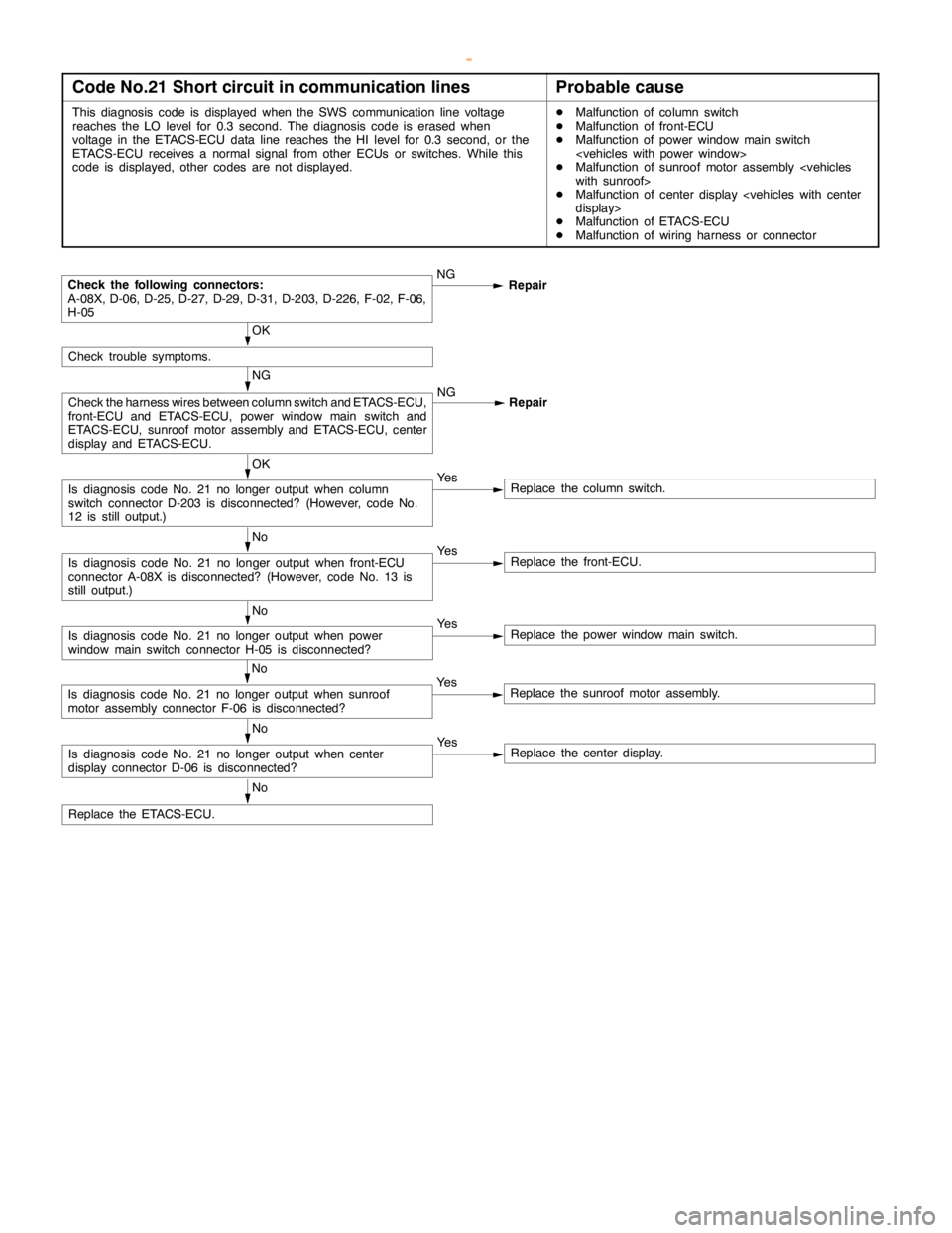
Code No.21 Short circuit in communication linesProbable cause
This diagnosis code is displayed when the SWS communication line voltage
reaches the LO level for 0.3 second. The diagnosis code is erased when
voltage in the ETACS-ECU data line reaches the HI level for 0.3 second, or the
ETACS-ECU receives a normal signal from other ECUs or switches. While this
code is displayed, other codes are not displayed.DMalfunction of column switch
DMalfunction of front-ECU
DMalfunction of power windowmainswitch
DMalfunction of sunroof motor assembly
DMalfunction of center display
DMalfunction of ETACS-ECU
DMalfunction of wiring harness or connector
NG
Repair
OK
Ye s
Replace the column switch.
No
Ye s
Replace the front-ECU.
No
Ye s
Replace the power windowmainswitch.
No
Ye s
Replace the center display.
No
Replace the ETACS-ECU.
No
Ye s
Replace the sunroof motor assembly.
Is diagnosis code No. 21 no longer output when center
display connector D-06 is disconnected?
Is diagnosis code No. 21 no longer output when sunroof
motor assembly connector F-06 is disconnected?
Is diagnosis code No. 21 no longer output when power
window mainswitch connector H-05 is disconnected?
Is diagnosis code No. 21 no longer output when front-ECU
connector A-08X is disconnected? (However, code No. 13 is
still output.)
Is diagnosis code No. 21 no longer output when column
switch connector D-203 is disconnected? (However, code No.
12 is still output.)
NG
Check the harness wires between column switch and ETACS-ECU,
front-ECU and ETACS-ECU, power windowmainswitch and
ETACS-ECU, sunroof motor assembly and ETACS-ECU, center
display and ETACS-ECU.NG
Repair
OK
Check trouble symptoms.
Check the following connectors:
A-08X, D-06, D-25, D-27, D-29, D-31, D-203, D-226, F-02, F-06,
H-05
www.WorkshopManuals.co.uk
Purchased from www.WorkshopManuals.co.uk