2000 MITSUBISHI MONTERO belt
[x] Cancel search: beltPage 53 of 1839

GENERAL -Precautions Before Service00-5
PRECAUTIONS BEFORE SERVICE
SUPPLEMENTAL RESTRAINT SYSTEM (SRS), SEAT BELT WITH PRE-TENSIONER
1. Items to follow when servicing SRS
(1) Be sure to read GROUP 52B - Supplemental Restraint System (SRS).
For safe operations, please follow the directions and heed all warnings.
(2) Wait at least 60 seconds after disconnecting the battery cable before doing any further work.
The SRS system is designed to retain enough voltage to deploy the air bag even after the battery
has been disconnected. Serious injury may result from unintended air bag deployment if work
is done on the SRS system immediately after the battery cable is disconnected.
(3) Warning labels must be heeded when servicing or handling SRS components and seat belt with
pre-tensioner. Warning labels are located in the following locations.
DHood
DSun visor
DGlove box
DSRS-ECU
DSteering wheel
DSteering gearbox
DAir bag module (driver’s side and front passenger’s side)
DFront impact sensor
DClock spring
DSeat belt with pre-tensioner
DSide air bag module
DSide impact sensor
(4) Always use the designated special tools and test equipment.
(5) Store components removed from the SRS and seat belt with pre-tensioner in a clean and dry
place.
The air bag module and seat belt with pre-tensioner should be stored on a flat surface and
placed so that the pad surface is facing upward.
Do not place anything on top of it.
(6) Never attempt to disassemble or repair the SRS components (SRS-ECU, air bag module, clock
spring and side impact sensor) and seat belt with pre-tensioner.
(7) Whenever you finish servicing the SRS and seat belt with pre-tensioner, check the SRS warning
lamp operation to make sure that the system functions properly.
(8) Be sure to deploy the air bag and seat belt with pre-tensioner before disposing of the air bag
module and seat belt with pre-tensioner or disposing of a vehicle equipped with an air bag and
seat belt with pre-tensioner. (Refer to GROUP 52B - Air Bag Module and Seat Belt with Pre-tensioner
Disposal Procedures.)
2. Observe the following when carrying out operations on places where SRS components and seat
belt with pre-tensioner are installed, including operations not directly related to the SRS air bag and
seat belt with pre-tensioner.
(1) When removing or installing parts do not allow any impact or shock to the SRS components
and seat belt with pre-tensioner.
(2) SRS components and seat belt with pre-tensioner should not be subjected to heat, so remove
the SRS components and seat belt with pre-tensioner before drying or baking the vehicle after
painting.
DSRS-ECU, air bag module, clock spring, front and side impact sensors: 93_C or more
DSeat belt with pre-tensioner: 90_C or more
After re-installing them, check the SRS warning lamp operation to make sure that the system
functions properly.
www.WorkshopManuals.co.uk
Purchased from www.WorkshopManuals.co.uk
Page 56 of 1839

11A-2
ENGINE <6G7>
CONTENTS
GENERAL INFORMATION 3..................
SERVICE SPECIFICATIONS 3.................
SEALANT 4..................................
SPECIAL TOOLS 4..........................
ON-VEHICLE SERVICE 6.....................
Drive Belt Tension Check and Adjustment 6......
Auto-tensioner Check 6.........................
Ignition Timing Check 6........................
Idle Speed Check 7............................
Idle Mixture Check 8...........................Compression Pressure Check 9.................
Intake Manifold Vacuum Check 10...............
Lash Adjuster Check 10........................
OIL PAN AND OIL SCREEN 13..............
TIMING BELT 15............................
CRANKSHAFT OIL SEAL 23.................
CAMSHAFT OIL SEAL 25...................
CYLINDER HEAD GASKET 27...............
ENGINE ASSEMBLY 30.....................
www.WorkshopManuals.co.uk
Purchased from www.WorkshopManuals.co.uk
Page 57 of 1839

ENGINE <6G7> -General Information/Service Specifications11A-3
GENERAL INFORMATION
Items6G74-GDI
Total displacement ml3,497
Bore´Stroke mm93´85.8
Compression ratio10.4
Combustion chamberPentroof + ball-in-piston
Camshaft arrangementDOHC
Number of valveIntake12
Exhaust12
Valve timingIntakeOpeningBTDC 8_
ClosingABDC 56_
ExhaustOpeningBBDC 48_
ClosingATDC 16_
Fuel systemElectronically controlled multipoint fuel injection
Rocker armRoller type
Auto-lash adjusterEquipped
SERVICE SPECIFICATIONS
ItemsStandard valueLimit
Basic ignition timing5_BTDC±3_-
Ignition timingApprox. 20_BTDC*1-
Idle speed r/min600±100*1-
CO contents %0.5 or less-
HC contents ppm100 or less-
Compression pressure (at engine speed of 280 r/min) kPa1,275980
Compression pressure difference of all cylinders kPa-Max. 98
Intake manifold vacuum kPa-Min. 56*2
Auto tensioner rod depth (mm)Within 1-
Timing belt tension torque N×m4.4-
Auto-tensioner rod protrusion amount mm3.8 - 5.0-
NOTE
*1: Indicates the value measured within 4 minutes since the engine was started.
*2: Indicates the value when more than 4 minutes have passed since the engine was started.
www.WorkshopManuals.co.uk
Purchased from www.WorkshopManuals.co.uk
Page 58 of 1839

S
EA LA NT
I te m s S
pecif ie d se ala nts R
em ark s O
il p an M
IT S U BIS H I GEN UIN E PA R T
M D970389 or equiv a le nt S
em i- d ry in g se ala nt N
um ber N
am e U
se M
B991502 M
UT-II su b
a sse m bly M
B991800 P
ulle y hold er S
upportin g of cra nksh aft p ulle y M
B991802 P
in B M
D998769 C
ra nksh aft pulle y
s p ace r O
pera tin g th e cra nksh aft w hen in sta llin g th e
t im in g belt M
D998767 T
e nsio n pulle y
s o cke t w re nch T
im in g belt te nsio n adju stm ent M
D998718 C
ra nksh aft re ar oil
s e alin sta lle r P
re ss-fit tin g th e cra nksh aft re ar oil se al M
D998781 F
ly w heelsto pper S
ecu rin g th e fly w heel
Page 60 of 1839

O
N-V EH IC LE SER VIC E
D RIV E BELT TE N SIO N CHEC K AND
A DJU STM EN T
C au tio n
P erfo rm th e ch eck afte r ro ta tin g th e en gin e to th e norm al
d ir e ctio n (o ne re vo lu tio n an d over).
1 . Check th at th e in dic a to r m ark of th e auto -te nsio ner is
l o ca te d wit h in th e sco pe sh ow n as ”A ” on th e te nsio ner
b ra cke t.
2 . If th e mark is lo ca te d out of th e sco pe ”A ,” re pla ce th e
d riv e belt .
N O TE
S in ce th e auto -te nsio ner is use d, it is not nece ssa ry to
a dju st th e te nsio n of th e belt .
A UTO -T E N SIO NER CHEC K
1 . Run th e engin e at id lin g sp eed and th en sto p it to ch eck
w heth er th e driv e belt is fo rc e d out fr o m th e wid th of
t h e auto -te nsio ner pulle y.
2 . Rem ove th e driv e belt . (R efe r P.1 1 A -1 7.)
3 . Move th e auto -te nsio ner rig ht and le ft by usin g a12.7
m m sp in ner handle and th e lik e to ch eck wheth er th ere
i s no ca tc h .
4 . If so m e abnorm alit y is fo und durin g th e above m entio ned
c h eck (1 ) and (3 ), re pla ce th e auto -te nsio ner.
5 . In sta ll th e driv e belt . (R efe r P.1 1 A -1 8.)
I G NIT IO N TIM IN G CHEC K
1 . Befo re in sp ectio n, se t th e ve hic le to th e pre -in sp ectio n
c o ndit io n.
2 . Turn th e ig nit io n sw it c h to th e LO CK (O FF) posit io n, and
t h en co nnect th e MUT-I I to th e dia gnosis co nnecto r.
3 . Set a tim in g lig ht to th e ig nit io n co il pow er su pply lin e
( in te rm edia te co nnecto r N o.7 te rm in al) ofth e ig nit io n co il
i n te rm edia te co nnecto r engin e-s id e harn ess.
4 . Sta rt th e engin e and le t it ru n at id le .
5 . Use th e MUT-I I to measu re engin e id le sp eed and ch eck
t h at it is wit h in th e sta ndard va lu e.
S ta n dard valu e: 600 ±
100 (7 00 ±
100)*
N O TE
* : In dic a te s th e va lu es when more th an 4 min ute s have
p asse d sin ce th e id lin g co ndit io n was sta rte d. M
UT-
I I
Page 69 of 1839

T
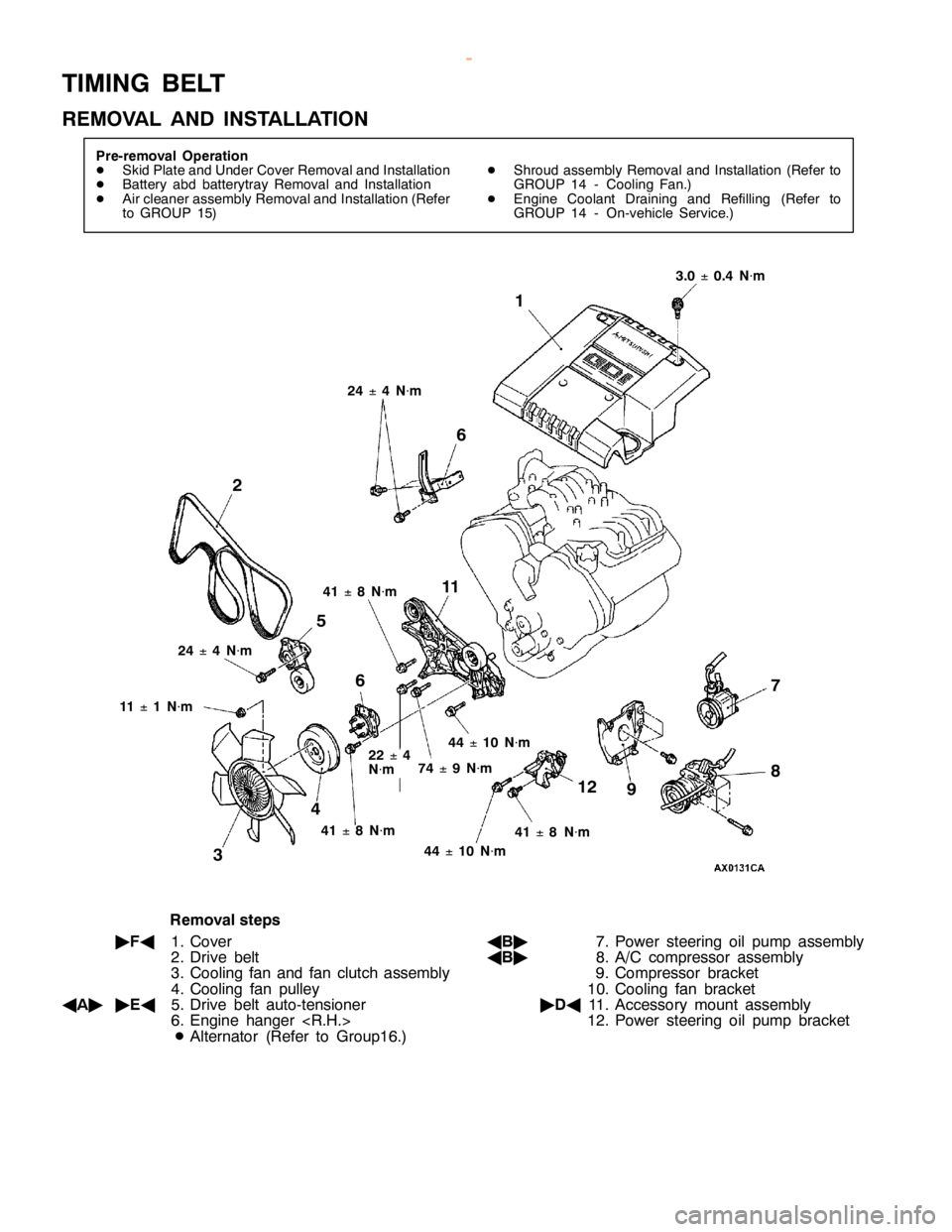
IM IN G BELT
R EM OVA L AND IN STA LLA TIO N 2
1
1 1
2 3 1
5
6
4 9 7
84
1
±8
N
×m 4
1
±8
N
×m 4
4
±1
0 N
×m 4
1
±8
N
×m 3
.0
±0
.4 N
×m 2
2
±4
N ×m 7
4
±9
N
×m 1
1
±1
N
×m 2
4
±4
N
×m 4
4
±1
0 N
×m
R em oval ste p s
" FA
1. C ove r
2 . D riv e belt
3 . C oolin g fa n and fa n clu tc h asse m bly
4 . C oolin g fa n pulle y
A A"
"
EA
5. D riv e belt auto -te nsio ner
6 . E ngin e hanger
D Alt e rn ato r (R efe r to Gro up16.) A
B"
7. P ow er ste erin g oil pum p asse m bly
A B"
8. A /C co m pre sso r asse m bly
9 . C om pre sso r bra cke t
1 0. C oolin g fa n bra cke t
" DA
11 . A cce sso ry mount asse m bly
1 2. P ow er ste erin g oil pum p bra cke t
w
ww.W ork sh opM an uals .c o .u k
P urc h ased f r o m w ww.W ork sh opM an uals .c o .u k
Page 70 of 1839

1
4 1
6 1
7 2
0 1
9 1
5 1
1
±1
N
×m 1
1
±1
N
×m 4
4
±1
0 N
×m 4
8
±6
N
×m 1
82
±4
N
×m
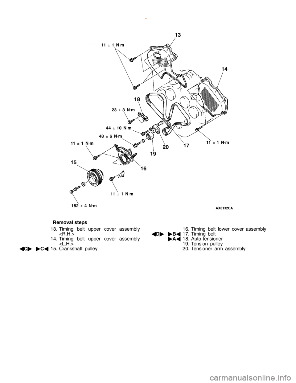
R em oval ste p s
1 3. Tim in g belt upper co ve r asse m bly
< R .H .>
1 4. Tim in g belt upper co ve r asse m bly
< L.H .>
A C"
"
CA
15. C ra nksh aft pulle y 1
6. Tim in g belt lo w er co ve r asse m bly
A D"
"
BA
17. Tim in g belt
" AA
18. A uto -te nsio ner
1 9. Te nsio n pulle y
2 0. Te nsio ner arm asse m bly
w
ww.W ork sh opM an uals .c o .u k
P urc h ased f r o m w ww.W ork sh opM an uals .c o .u k
Page 81 of 1839

C
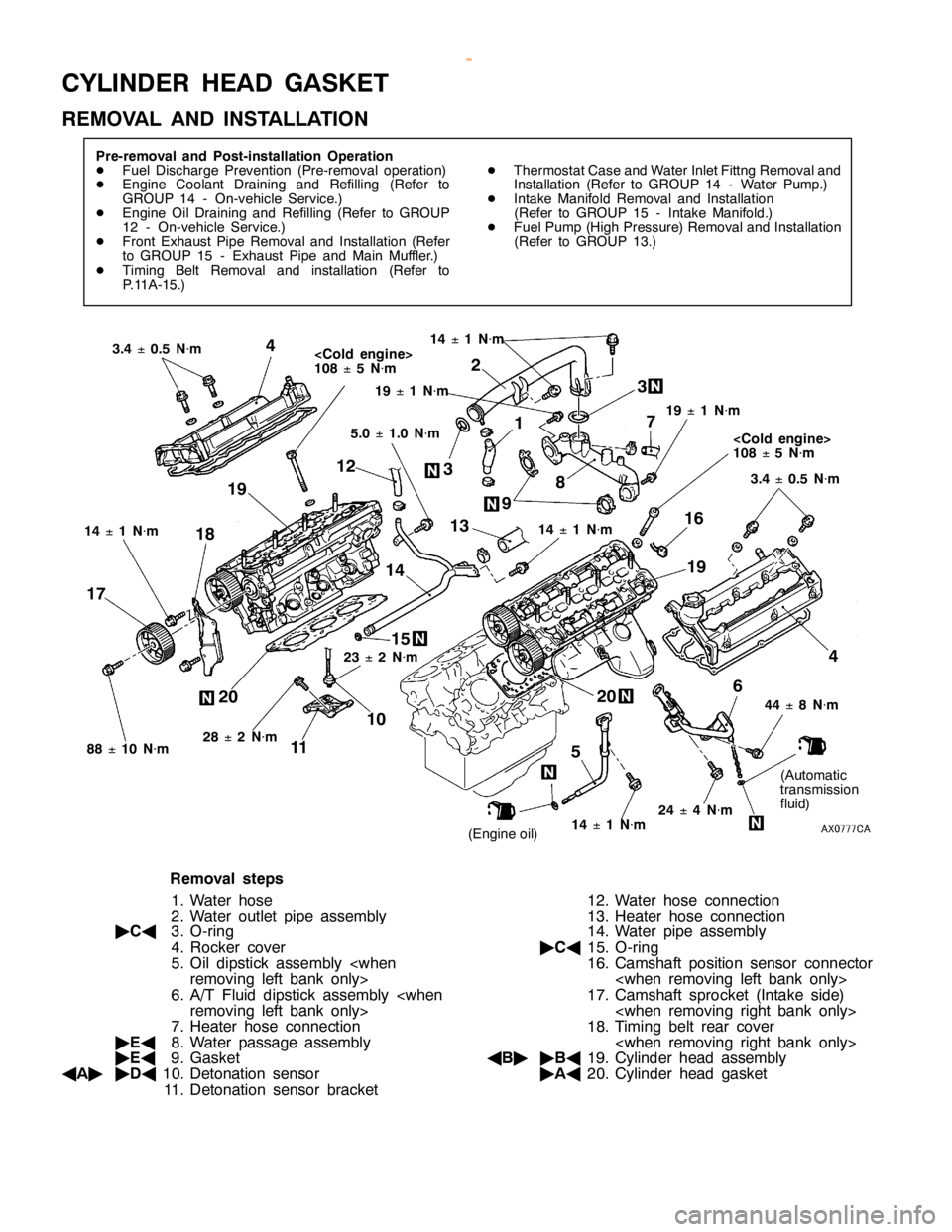
YLIN DER HEA D GASK ET
R EM OVA L AND IN STA LLA TIO N 4
5
4 6
7
8
9 1
0
1 1 1
2
13
1 4
1 5 1
6
1 7 1
8
23
±2
N
×m
2 8
±2
N
×m (
A uto m atic
t r a nsm is sio n
f lu id )
<
C old en gin e>
1 08
±5
N
×m
R em oval ste p s
1 . W ate r hose
2 . W ate r outle t pip e asse m bly
" CA
3. O -rin g
4 . R ocke r co ve r
5 . O il dip stic k asse m bly
6 . A /T Flu id dip stic k asse m bly
7 . H eate r hose co nnectio n
" EA
8. W ate r passa ge asse m bly
" EA
9. G aske t
A A"
"
DA
10. D eto natio n se nso r
1 1 . D eto natio n se nso r bra cke t 1
2. W ate r hose co nnectio n
1 3. H eate r hose co nnectio n
1 4. W ate r pip e asse m bly
" CA
15. O -rin g
1 6. C am sh aft posit io n se nso r co nnecto r
< w hen re m ovin g le ft bank only >
1 7. C am sh aft sp ro cke t (In ta ke sid e)
< w hen re m ovin g rig ht bank only >
1 8. Tim in g belt re ar co ve r
< w hen re m ovin g rig ht bank only >
A B"
"
BA
19. C ylin der head asse m bly
" AA
20. C ylin der head gaske t
w
ww.W ork sh opM an uals .c o .u k
P urc h ased f r o m w ww.W ork sh opM an uals .c o .u k