2000 MITSUBISHI MONTERO Indicator
[x] Cancel search: IndicatorPage 820 of 1839

ENGINE AND EMISSION CONTROL -Auto-cruise Control System17-18
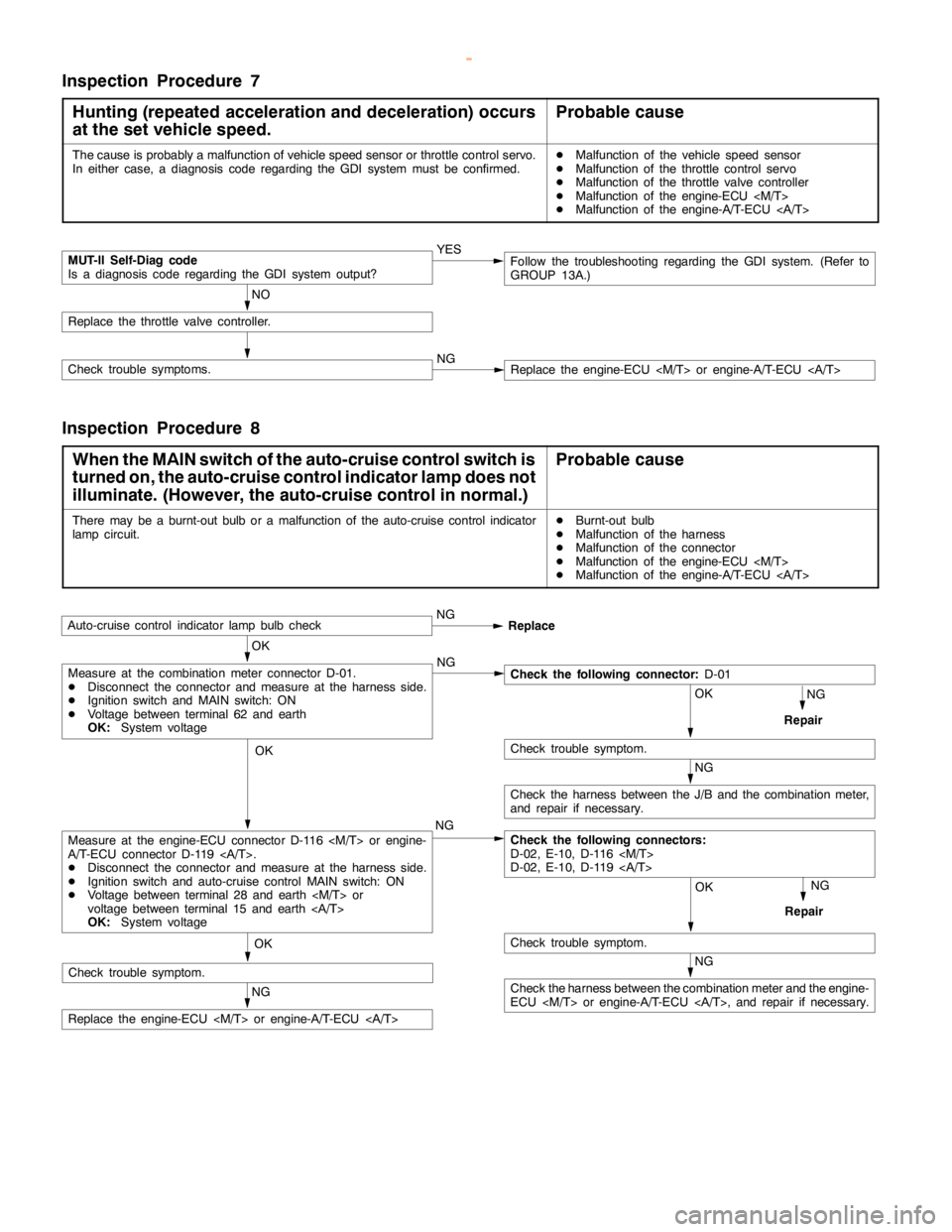
Inspection Procedure 7
Hunting (repeated acceleration and deceleration) occurs
at the set vehicle speed.
Probable cause
The cause is probably a malfunction of vehicle speed sensor or throttle control servo.
In either case, a diagnosis code regarding the GDI system must be confirmed.DMalfunction of the vehicle speed sensor
DMalfunction of the throttle control servo
DMalfunction of the throttle valve controller
DMalfunction of the engine-ECU
DMalfunction of the engine-A/T-ECU
MUT-II Self-Diag code
Is a diagnosis code regarding the GDI system output?YES
NO
Replace the throttle valve controller.
Check trouble symptoms.NGReplace the engine-ECU
Follow the troubleshooting regarding the GDI system. (Refer to
GROUP 13A.)
Inspection Procedure 8
When the MAIN switch of the auto-cruise control switch is
turned on, the auto-cruise control indicator lamp does not
illuminate. (However, the auto-cruise control in normal.)
Probable cause
There may be a burnt-out bulb or a malfunction of the auto-cruise control indicator
lampcircuit.DBurnt-out bulb
DMalfunction of the harness
DMalfunction of the connector
DMalfunction of the engine-ECU
DMalfunction of the engine-A/T-ECU
OK
Auto-cruise control indicatorlamp bulbcheckNG
Replace
NG
Repair
OK
NG
OK
Check trouble symptom.
NG
Check the harness between the J/B and the combination meter,
and repair if necessary.
Check the following connectors:
D-02, E-10, D-116
D-02, E-10, D-119
OK
Check trouble symptom.
NG
Repair
NG
Replace the engine-ECU
Measure at the engine-ECU connector D-116
A/T-ECU connector D-119 .
DDisconnect the connector and measure at the harness side.
DIgnition switch and auto-cruise control MAIN switch: ON
DVoltage between terminal 28 and earth
voltage between terminal 15 and earth
OK:System voltage
Measure at the combination meter connector D-01.
DDisconnect the connector and measure at the harness side.
DIgnition switch and MAIN switch: ON
DVoltage between terminal 62 and earth
OK:System voltageCheck the following connector:D-01
NG
Check the harness between the combination meter and the engine-
ECU
Check trouble symptom.
www.WorkshopManuals.co.uk
Purchased from www.WorkshopManuals.co.uk
Page 822 of 1839

ENGINE AND EMISSION CONTROL -Auto-cruise Control SystemENGINE AND EMISSION CONTROL -Auto-cruise Control System17-20
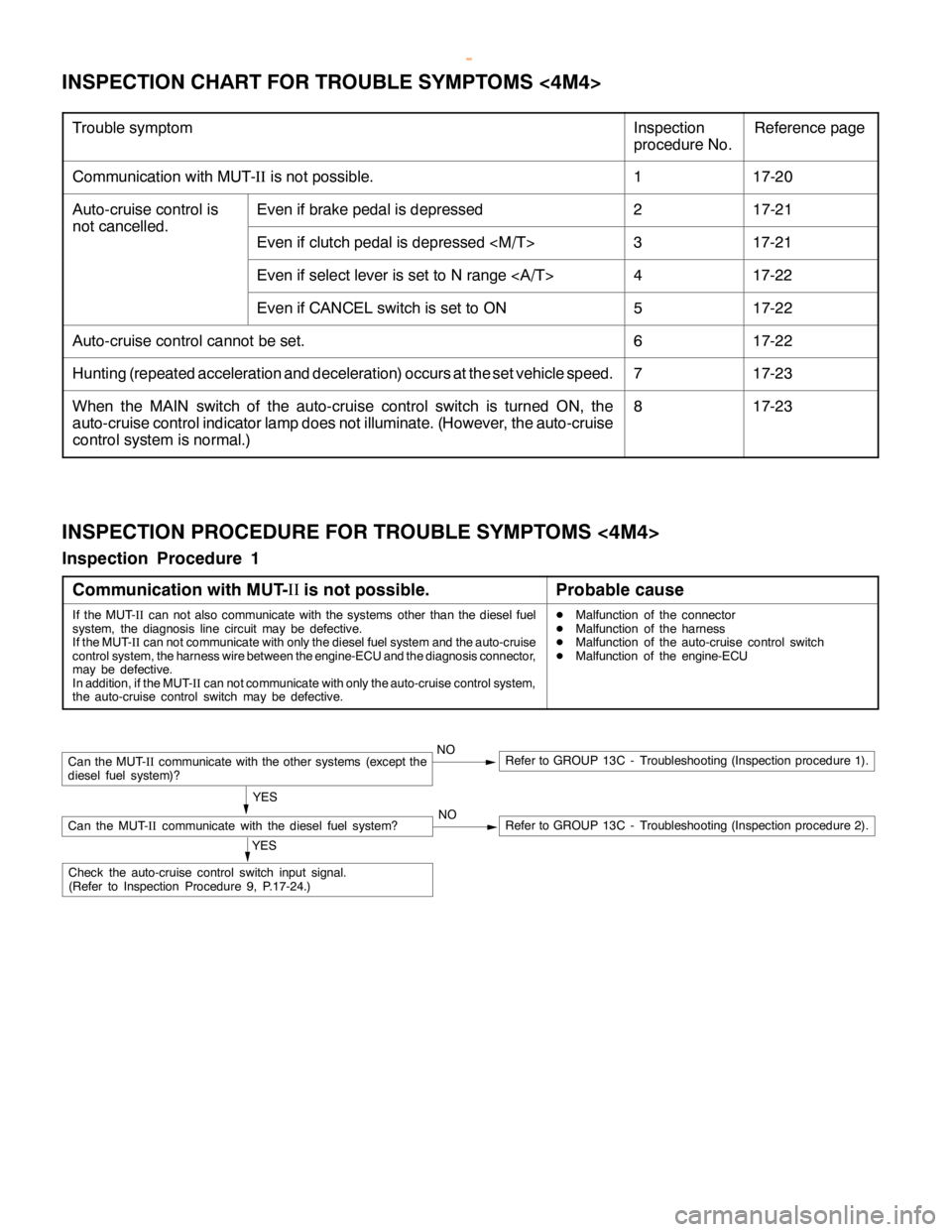
INSPECTION CHART FOR TROUBLE SYMPTOMS <4M4>
Trouble symptomInspection
procedure No.Reference page
Communication with MUT-IIis not possible.117-20
Auto-cruise control isEven if brake pedal is depressed217-21
not cancelled.
Even if clutch pedal is depressed
Even if select lever is set to N range417-22
Even if CANCEL switch is set to ON517-22
Auto-cruise control cannot be set.617-22
Hunting (repeated acceleration and deceleration) occurs at the set vehicle speed.717-23
When the MAIN switch of the auto-cruise control switch is turned ON, the
auto-cruise control indicator lamp does not illuminate. (However, the auto-cruise
control system is normal.)817-23
INSPECTION PROCEDURE FOR TROUBLE SYMPTOMS <4M4>
Inspection Procedure 1
Communication with MUT-II
is not possible.
Probable cause
If the MUT-
IIcan not also communicate with the systems other than the diesel fuel
system, the diagnosis line circuit may be defective.
If the MUT-
IIcan not communicate with only the diesel fuel system and the auto-cruise
control system, the harness wire between the engine-ECU and the diagnosis connector,
may be defective.
In addition, if the MUT-
IIcan not communicate with only the auto-cruise control system,
the auto-cruise control switch may be defective.DMalfunction of the connector
DMalfunction of the harness
DMalfunction of the auto-cruise control switch
DMalfunction of the engine-ECU
NORefer to GROUP 13C - Troubleshooting (Inspection procedure 2).
Can the MUT-
IIcommunicate with the other systems (except the
diesel fuel system)?NORefer to GROUP 13C - Troubleshooting (Inspection procedure 1).
YES
Can the MUT-
IIcommunicate with the diesel fuel system?
YES
Check the auto-cruise control switch input signal.
(Refer to Inspection Procedure 9, P.17-24.)
www.WorkshopManuals.co.uk
Purchased from www.WorkshopManuals.co.uk
Page 825 of 1839

ENGINE AND EMISSION CONTROL -Auto-cruise Control System17-23
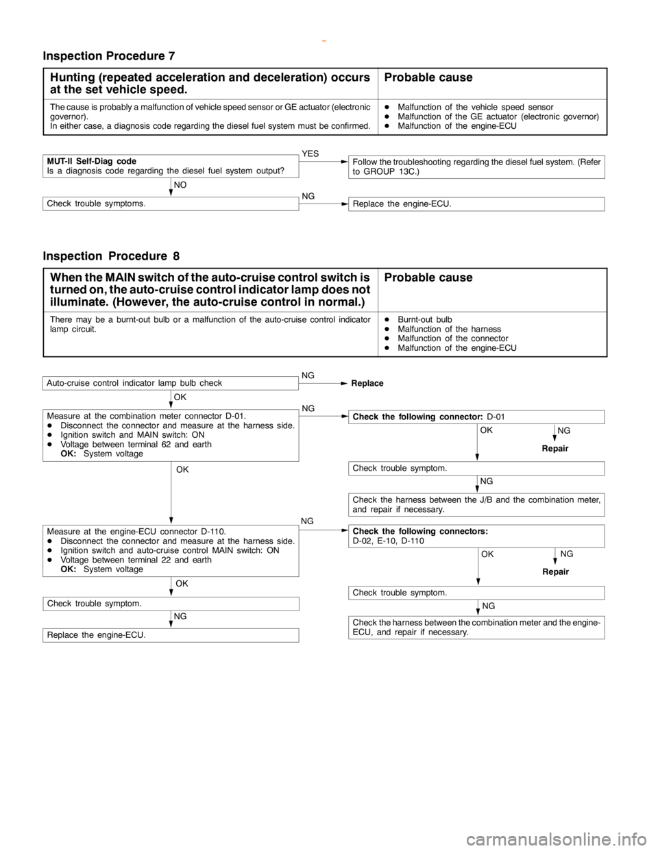
Inspection Procedure 7
Hunting (repeated acceleration and deceleration) occurs
at the set vehicle speed.
Probable cause
The cause is probably a malfunction of vehicle speed sensor or GE actuator (electronic
governor).
In either case, a diagnosis code regarding the diesel fuel system must be confirmed.DMalfunction of the vehicle speed sensor
DMalfunction of the GE actuator (electronic governor)
DMalfunction of the engine-ECU
MUT-II Self-Diag code
Is a diagnosis code regarding the diesel fuel system output?YES
NO
Check trouble symptoms.NGReplace the engine-ECU.
Follow the troubleshooting regarding the diesel fuel system. (Refer
to GROUP 13C.)
Inspection Procedure 8
When the MAIN switch of the auto-cruise control switch is
turned on, the auto-cruise control indicator lamp does not
illuminate. (However, the auto-cruise control in normal.)
Probable cause
There may be a burnt-out bulb or a malfunction of the auto-cruise control indicator
lampcircuit.DBurnt-out bulb
DMalfunction of the harness
DMalfunction of the connector
DMalfunction of the engine-ECU
OK
Auto-cruise control indicatorlamp bulbcheckNG
Replace
NG
Repair
OK
NG
OK
Check trouble symptom.
NG
Check the harness between the J/B and the combination meter,
and repair if necessary.
Check the following connectors:
D-02, E-10, D-110
OK
Check trouble symptom.
NG
Repair
NG
Replace the engine-ECU.NG
Measure at the engine-ECU connector D-110.
DDisconnect the connector and measure at the harness side.
DIgnition switch and auto-cruise control MAIN switch: ON
DVoltage between terminal 22 and earth
OK:System voltage
Measure at the combination meter connector D-01.
DDisconnect the connector and measure at the harness side.
DIgnition switch and MAIN switch: ON
DVoltage between terminal 62 and earth
OK:System voltageCheck the following connector:D-01
NG
Check the harness between the combination meter and the engine-
ECU, and repair if necessary. OK
Check trouble symptom.
www.WorkshopManuals.co.uk
Purchased from www.WorkshopManuals.co.uk
Page 881 of 1839

22-1
MANUAL
TRANSMISSION
CONTENTS
GENERAL INFORMATION 2..................
LUBRICANTS 2..............................
SEALANTS 2................................
SPECIAL TOOL 2............................
TROUBLESHOOTING
ON-VEHICLE SERVICE 6.....................
Transmission Oil Check 6.......................
Oil Replacement 6.............................4WD Detection Switch Continuity Check
High/Low Detection Switch Continuity Check
TRANSMISSION CONTROL
TRANSMISSION CONTROL
TRANSMISSION ASSEMBLY 10..............
4WD INDICATOR-ECU/TRANSFER-ECU 17....
www.WorkshopManuals.co.uk
Purchased from www.WorkshopManuals.co.uk
Page 898 of 1839

MANUAL TRANSMISSION -4WD Indicator-ECU/Transfer-ECU22-18
Terminal No.Inspection itemInspection condition
1: Ignition switchInspection condition
2: Transfer lever positionTerminal voltage
1Free wheel engageON2HSystem voltage
switch
4H*10V
24WD detectionON2HSystem voltage
switch
4H, 4L0V
3Ignition switch (IG1)OFF-0V
ON-System voltage
6HI/LOW detection
switchONShifting from 4H to 4L
or vice versaSystem voltage
2H, 4H, 4L0V
7Free wheel clutchON4H, 4L0V
changeover solenoid
valve
2H*2System voltage
104WD Indicator lampON2H0V
4H, 4LSystem voltage
NOTE
*1:When vehicle has been moved once.
*2:Shift the lever from 4H to 2H, and then turn the ignition switch to OFF and then back to ON.
TRANSFER-ECU
Measure the terminal voltage (Refer to P.22-3).
www.WorkshopManuals.co.uk
Purchased from www.WorkshopManuals.co.uk
Page 902 of 1839

Page 906 of 1839

AUTOMATIC TRANSMISSION -Troubleshooting AUTOMATIC TRANSMISSION -Troubleshooting 23-5
ROAD TEST
No.Pre-test/opera-
tion conditionsTest/operationJudgment valueCheck itemDiag-
nosis
code
No.Inspection pro-
cedure if there is
an abnormality
1Ignition switch:
OFFIgnition switch
(1) ONData List No. 54
(1) 10 - 12 VA/T control
relay54A/T control relay
system
2Ignition switch:
ON
Engine:Stop
Selector lever
position: PSelector lever posi-
tion
(1) P
(2) R
(3) N
(4) DData List No. 61
(1) P
(2) R
(3) N
(4) DInhibitor
switch-Inhibitor switch
system
Selector lever opera-
tion
(1) D (1st)
(2) Sports mode se-
lected (1st)
(3) Lever moved toData List
No.67 No.68 No.69
(1)OFF OFF OFF
(2)ON OFF OFF
(3)ON ON OFF
(4)ON OFF ON
Select switch
Upshift
switch
Downshift
switch-Sports mode
switch system
upshift position
and held (2nd)
(4) Lever moved to
downshift
position and held
(1st)Shift indicator lamp
(1) D and 1
illuminate
(2) Only 1
illuminates
(3) Only 2
illuminates
(4) Only 1
illuminates
Accelerator pedal
(1) Fully closed
(2) Depressed
(3) Fully openedData List No. 11
(1) 985 - 1,085 mV
(2) Gradually in-
creases from (1)
(3) 4,000 mV or
moreAPS11
12
14APS system
Data list No.25
(1) OFF
(2) ONWide open
throttle
switch25Wide open
throttle switch
system
2Ignition switch:
ON
Engine: StopBrake pedal
(1) Depressed
(2) ReleasedData List No. 26
(1) ON
(2) OFFStop lamp
switch26Stop lamp
switch system
Selector lever
position: PTransfer shift lever
position
(1) Except for 4LLc
(2) 4LLcData List No. 75
(1) OFF
(2) ON4LLc switch-4LLc switch sys-
tem
www.WorkshopManuals.co.uk
Purchased from www.WorkshopManuals.co.uk
Page 921 of 1839
