2000 MITSUBISHI MONTERO set clock
[x] Cancel search: set clockPage 36 of 1839

GENERAL -Supplemental Restraint System (SRS)00-35
SRS-ECU
Terminal No.Destination of harnessCorrective action
1, 2, 3, 4Instrument panel wiring harness®Front wiring harness®Front
impact sensorRepair or replace each wiring
harness
7Instrument panel wiring harness®EarthRepair or replace Instrument
8Instrument panel wiring harness®Combination meter
(SRS warning lamp)
panel wiring harness
9, 10Instrument panel wiring harness®Front passenger’s air bag
module
11 , 1 2Instrument panel wiring harness®Clock spring®Driver’s air bag
module)Repair or replace the Instrument
panel wiring harness. Replace
clock spring.
13Instrument panel wiring harness®Junction block (fuse No.8)Repair or replace Instrument
16Instrument panel wiring harness®Junction block (fuse No.6)
panel wiring harness.
20Instrument panel wiring harness®Diagnosis connector
21, 22Side air bag wiring harness®Side air bag module (L.H.)Repair or replace side air bag
23, 24Side air bag wiring harness®Side air bag module (R.H.)
wiring harness.
34, 35, 36Side air bag wiring harness®Floor wiring harness®Side impact
sensor (L.H.)Repair or each wiring harness.
40, 41, 42Side air bag wiring harness®Floor wiring harness®Side impact
sensor (R.H.)
6. Inspection of the SRS-ECU harness connector should be carried out by the following procedure.
Insert the special tool (probe, MB991222, in the harness set) into the connector from harness side
(rear side), and connect the tester to this probe. If any tool than specified is used, damage to the
harness and other components will result. Furthermore, measurement should not be carried out by
touching the probe directly against the terminals from the front of the connector. The terminals are
plated to increase their conductivity, so that if they are touched directly by the probe, the plating
may break, which will cause drops in reliability.
www.WorkshopManuals.co.uk
Purchased from www.WorkshopManuals.co.uk
Page 1165 of 1839

POWER PLANT MOUNT - No.1 Crossmember32-7
No.1 CROSSMEMBER
REMOVAL AND INSTALLATION
Caution
1. Before removing the steering wheel and airbag module assembly, always refer to GROUP 52B
- Service Precautions, Airbag Module and Clock Spring. Also, set the front wheels so that
they are facing straight forward, and remove the ignition key. If you fail to do this, the SRS
clock spring will be damaged, causing the SRS airbag to be inoperative and serious injury.
2. *: Indicates parts which should be initially tightened, and then fully tightened after placing
the vehicle horizontally and loading the full weight of the engine on the vehicle body.
Pre-removal Operation
DUnder Cover Removal
DDrive Shaft Removal
(Refer to GROUP 26.)
DDifferential Carrier and No.2 Crossmember
Assembly Removal (Refer to GROUP 26 -
Freewheel Assembly and Differential Carrier.)
DUpper Arm Removal
(Refer to GROUP 33A.)
DLower Arm Removal
(Refer to GROUP 33A.)
DStabilizer Bar Removal
(Refer to GROUP 33A.)
DEngine Oil Cooler Removal<6G7>
(Refer to GROUP 12.)
DAir Cleaner Removal<4M4>
(Refer to GROUP 15.)
DIntercooler Removal<4M4>
(Refer to GROUP 15.)
DEngine Cover Removal
(Refer to GROUP 11A - Timing Belt.)
DRadiator Removal
(Refer to GROUP 14.)
DPower Steering Fluid Draining
(Refer to GROUP 37A - On - vehicle Service.)Post - installation Operations
DDifferential Carrier and No.2 Crossmember
Assembly Installation (Refer to GROUP 26 -
Freewheel Assembly and Differential Carrier.)
DDrive Shaft Installation
(Refer to GROUP 26.)
DLower Arm Installation
(Refer to GROUP 33A.)
DUpper Arm Installation
(Refer to GROUP 33A.)
DStabilizer Bar Installation
(Refer to GROUP 33A.)
DAir Cleaner Installation<4M4>
(Refer to GROUP 15.)
DIntercooler Installation<4M4>
(Refer to GROUP 15.)
DRadiator Installation
(Refer to GROUP 14.)
DEngine Oil Cooler Installation
(Refer to GROUP 12.)
DPower Steering Fluid Supplying
(Refer to GROUP 37A - On - vehicle Service.)
DPower Steering Fluid Line Bleeding
(Refer to GROUP 37A - On - vehicle Service.)
DPress the dust cover with a finger tocheck whether
the dust cover is cracked or damaged.
DChecking Steering Wheel Position with Wheels
StraightAhead
DFront Wheel AlignmentCheck and Adjustment
(Refer to GROUP 37A - On - vehicle Service.)
DUnder Cover Installation
DEngine Cover Installation
(Refer to GROUP 11A - Timing Belt.)
www.WorkshopManuals.co.uk
Purchased from www.WorkshopManuals.co.uk
Page 1510 of 1839

SRS -Troubleshooting52B-10
Code No.21, 22, 61, 62 Driver’s side air bag module (squib)
systemProbable cause
These diagnosis codes are output if there is an abnormal resistance between the
input terminals of the driver’s side air bagmodule(squib) inside the SRS-ECU.
The trouble causes for each diagnosis code No. are as follow.
However, as for code Nos.21 and 22, if the vehicle’s condition return to normal,
SRS warning lampwill go out. (Diagnosis code will remain stored)DMalfunction of clock spring
DPartially open asclock spring is not in neutral
position
DMalfunction of harness or connector
DMalfunction of driver’s air bagmodule(squib)
DMalfunction of SRS-ECU
Table 3
Code No.Trouble Symptom
21D
Short circuit in driver’s air bag module (squib) or harness short
D
Short circuit in clock spring
D
Poor connector contact*
22D
Open circuit in driver’s air bag module (squib) or open harness
D
Open circuit in clock spring
D
Disconnected driver’s air bag module (squib) connector
D
Partially open as clock spring is not in neutral position
D
Poor connector contact
61Short circuit in driver’s air bag module (squib) harness leading to the power supply
62Short circuit in driver’s air bag module (squib) harness leading to the earth
NOTE
*: The shorting bars, which short positive (+) and negative ( - ) wires to prevent the air bags from accidental
deployment during the disconnection of the connector, are set in the squib circuit connectors. In
a defective connector, the short-bar may be still working even after the connection of the connecter.
www.WorkshopManuals.co.uk
Purchased from www.WorkshopManuals.co.uk
Page 1624 of 1839

CHASSIS ELECTRICAL -Clock or Center Display54A-54
BEFORE REMOVING THE BATTERY
The Center display has a large amount of data unique to the vehicle in its memory. When the battery
cable is disconnected, that memory is affected as shown in the table below. Accordingly, it is necessary
to make sure that you take notes of important information before disconnecting the battery cable.
FunctionInput function/memoryWhen battery cable is disconnected
Clock set on displayCurrent timeRetains data for approx. 1 hour
Vehicle model setShort (3-door models)/long (5-door
models)Retains data for approx. 1 hour
Brightness set for displayPosition set on displayRetains data for approx. 1 hour
Unit set for trip computerkm or mile, L/100km or mpg or km/L
Average vehicle speed after resetRetains data for approx. 1 hour
Average vehicle speed on displayAverage vehicle speed after resetRetains data for approx. 1 hour
Average fuel consumption on displayAverage fuel consumption after resetRetains data for approx. 1 hour
Cruising range on displayCruising range, fuel economyRetains data for approx. 1 hour
Outside temperature on displayOutside temperature after the ignition
switch is turned to the OFF(LOCK)
position.Retains data for approx. 1 hour
* The outside temperature sensor
is located near the engine.
Therefore, incorrectly high
temperature may be displayed
when the battery cable is
reconnected within one hour.
DIAGNOSIS FUNCTION FOR CENTER DISPLAY
Center display has the following diagnosis function:
FunctionContents
Service functionThere are the following 4 diagnosis modes available
1. Check of vehicle informationThe vehicle, short (3-door models)/long (5-door models) set
2. Check of LCD segmentsThe LCD segments for display available to light on or not
3. Check of sensorsOutside temperature, voltage of fuel gauge unit, system voltage, fuel amount
remains, fuel economy calculated after supply of fuel
4. Check of units connected into
the center displayThe units connected on display
Voltage (%) on terminal for MUT-II
Vehicle speed signal sent by engine-ECU
Oscillating signal
www.WorkshopManuals.co.uk
Purchased from www.WorkshopManuals.co.uk
Page 1632 of 1839

CHASSIS ELECTRICAL -Clock or Center Display54A-62
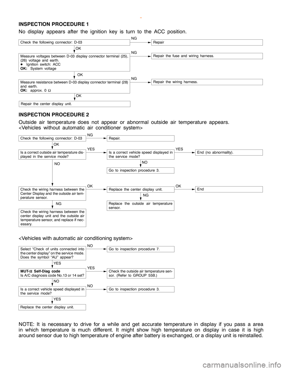
INSPECTION PROCEDURE 1
No display appears after the ignition key is turn to the ACC position.
OK
Measure voltages between D-03 display connector terminal (25),
(26) voltage and earth.
DIgnition switch: ACC
OK:System voltageNGRepair the fuse and wiring harness.
OK
Measure resistance between D-03 display connector terminal (28)
and earth.
OK:approx. 0
WNGRepair the wiring harness.
OK
Repair the center display unit.
Check the following connector: D-03NGRepair
INSPECTION PROCEDURE 2
Outside air temperature does not appear or abnormal outside air temperature appears.
Check the following connector: D-03NGRepair.
NO
Go to inspection procedure 3.
Check the wiring harness between the
Center Display and the outside air tem-
perature sensor.OKReplace the center display unit.OKEnd
NG
Replace the outside air temperature
sensor.NG
Check the wiring harness between the
center display unit and the outside air
temperature sensor, and replace if nec-
essary.
OK
Is a correct outside air temperature dis-
played in the servicemode?YESIs a correct vehicle speed displayed in
the servicemode?YESEnd (no abnormality).
NO
Select “Check of units connected into
the center display” on the service mode.
Does the symbol “AU” appear?NOGo to inspection procedure 7.
YES
Replace the center display unit.
YES
MUT-
IISelf-Diag code
Is A/C diagnosis code No.13 or 14 set?YESCheck the outside air temperature sen-
sor. (Refer to GROUP 55B.)
NO
Is a correct vehicle speed displayed in
the servicemode?NOGo to inspection procedure 3.
NOTE: It is necessary to drive for a while and get accurate temperature in display if you pass a area
in which temperature is much different. It might show high temperature on display in case it is high
around sensor due to high temperature of engine after battery is exchanged, or a display unit is reinstalled.
www.WorkshopManuals.co.uk
Purchased from www.WorkshopManuals.co.uk
Page 1635 of 1839

CHASSIS ELECTRICAL -Clock or Center Display54A-65
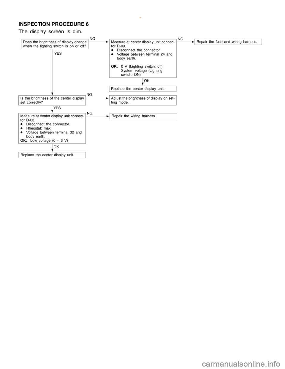
INSPECTION PROCEDURE 6
The display screen is dim.
NOMeasure at center display unit connec-
tor D-03.
DDisconnect the connector.
DVoltage between terminal 24 and
body earth.
OK:0 V (Lighting switch: off)
System voltage (Lighting
switch: ON)NGRepair the fuse and wiring harness.
Is the brightness of the center display
set correctly?NOAdjust the brightness of display on set-
ting mode.
OK
Replace the center display unit.
OK
Replace the center display unit.
YES
Measure at center display unit connec-
tor D-03.
DDisconnect the connector.
DRheostat: max
DVoltage between terminal 32 and
body earth.
OK:Low voltage (0 - 3 V)NGRepair the wiring harness.
Does the brightness of display change
when the lighting switch is on or off?
YES
www.WorkshopManuals.co.uk
Purchased from www.WorkshopManuals.co.uk
Page 1636 of 1839

CHASSIS ELECTRICAL -Clock or Center Display54A-66
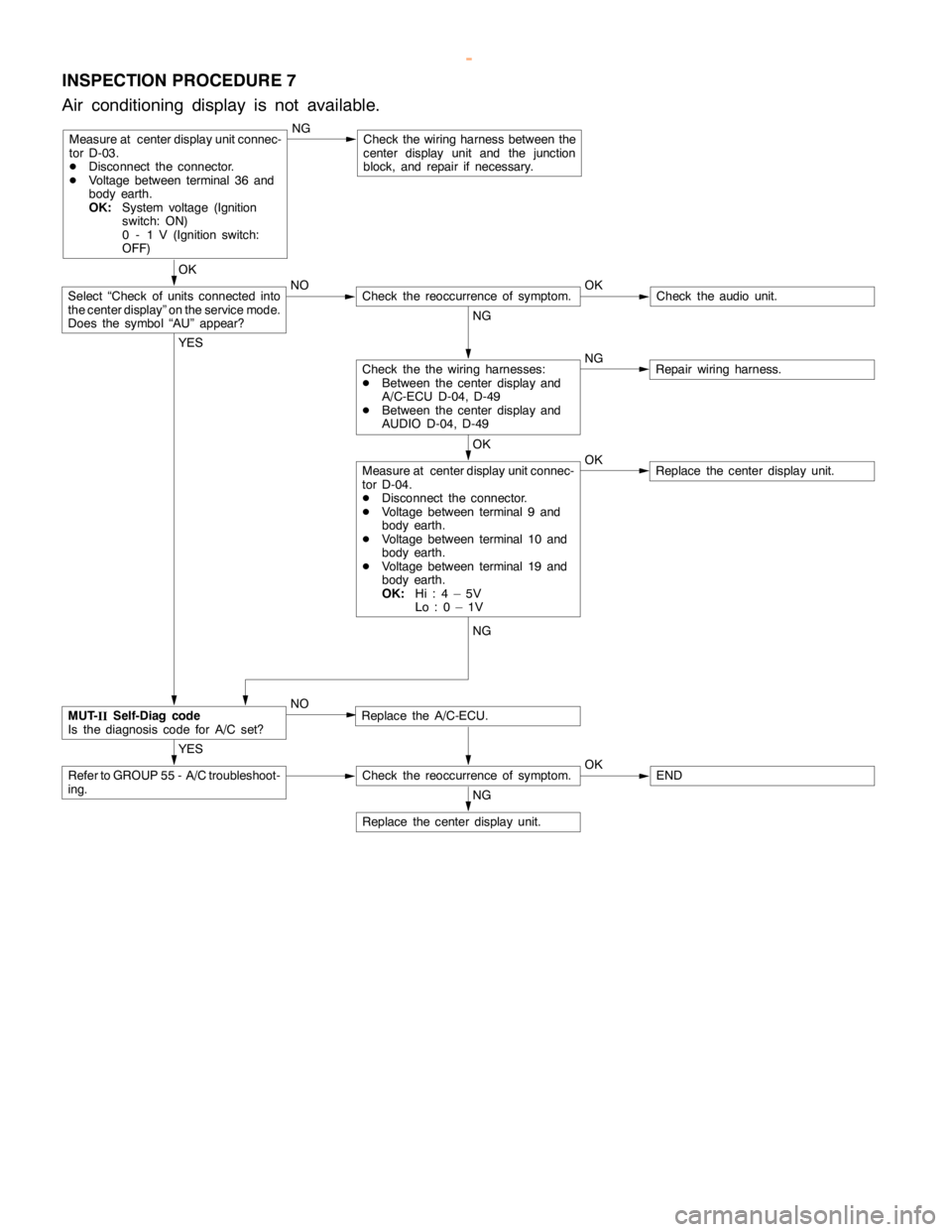
INSPECTION PROCEDURE 7
Air conditioning display is not available.
Measure at center display unit connec-
tor D-03.
DDisconnect the connector.
DVoltage between terminal 36 and
body earth.
OK:System voltage (Ignition
switch: ON)
0 - 1 V (Ignition switch:
OFF)NGCheck the wiring harness between the
center display unit and the junction
block, and repair if necessary.
OK
NO OK
Check theaudio unit.
NG
NG
Repair wiring harness.
OK
OK
Replace the center display unit.
YES
Replace the A/C-ECU.
YES
Refer to GROUP 55 - A/C troubleshoot-
ing.Check the reoccurrence of symptom.OKEND
NG
Replace the center display unit.
Measure at center display unit connec-
tor D-04.
DDisconnect the connector.
DVoltage between terminal 9 and
body earth.
DVoltage between terminal 10 and
body earth.
DVoltage between terminal 19 and
body earth.
OK:Hi:4–5V
Lo:0–1V
Check the the wiring harnesses:
DBetween the center display and
A/C-ECU D-04, D-49
DBetween the center display and
AUDIO D-04, D-49
Check the reoccurrence of symptom.Select “Check of units connected into
the center display” on the service mode.
Does the symbol “AU” appear?
MUT-
IISelf-Diag code
Is the diagnosis code for A/C set?NG
NO
www.WorkshopManuals.co.uk
Purchased from www.WorkshopManuals.co.uk
Page 1678 of 1839

CHASSIS ELECTRICAL -RV Meter54A-17
Termi-Input/out-
t
Signal sym-
bl
Terminal
lt
Harness problemTrouble symptoms when there is a
hblnal No.
p
put
gy
bolvoltage
(V)Open
circuitshort-cir-
cuit
yp
harness problem
11 - 1 4––––––
15Input/out-
putK (engine
K-LINE
signal)Hi: Sys-
tem volt-
age
Lo:0 - 1ExistsExistsDWiring communication error
DCommunication between the
engine-A/T-ECU
DAbnormal driving information
numerical display
16––––––
17Input/out-
putM-BUSY
(AUDIO)Hi:System
voltage
Lo:0 - 1ExistsExistsDAudio information does not
appear on the screen.
18–SHIELD-
EARTH
(AUDIO)––––
19Input/out-
putM-BUSY
(A/C)Hi:System
voltage
Lo:0 - 1ExistsExistsDAir conditioner information does
not appear on the screen.
DAmbient temperature is not
displayed.
20–SHIELD-
EARTH––––
22 - 21––––––
23InputAmbient
temperature
sensor–ExistsExistsDAmbient temperature is not
displayed.
24InputILL + (Light-
ing switch)Hi:System
voltage
Lo:0 - 1ExistsExistsDoes not illuminate.
25InputACC (ACC
power sup-
l)
System
voltageExists–Screen does not appear. No
operations are possible.
pp
ply)
g
–ExistsBlown multi-purpose fuse
26Input+BSystem
voltageExists–Screen does not appear. No
operations are possible.
g
–ExistsBlown multi-purpose fuse
27InputVSS (Vehicle
speed pulse
signal)Hi:System
voltage
Lo:0 - 1ExistsExistsDAbnormal “Distance km after
replacement” display in mainte-
nance screen
DSwitches which are not
supposed to operate during
driving do operate.
(Example:clock adjustment
screen, maintenance settings,
etc.)
DAmbient temperature display is
abnormally high.
28–Earth–Exists–Screen does not appear.
www.WorkshopManuals.co.uk
Purchased from www.WorkshopManuals.co.uk