2000 MITSUBISHI MONTERO display
[x] Cancel search: displayPage 1704 of 1839
SWS -Troubleshooting54B-18
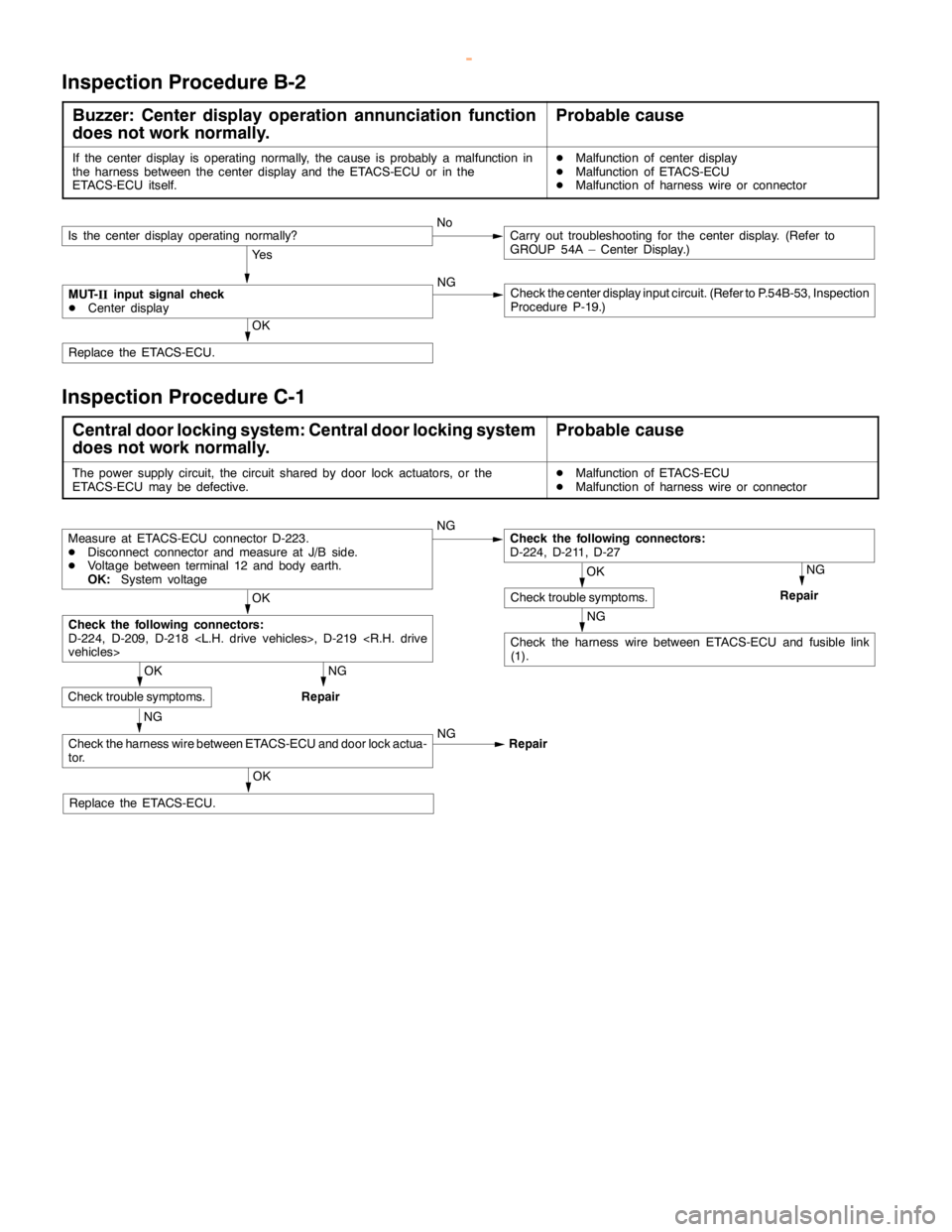
Inspection Procedure B-2
Buzzer: Center display operation annunciation function
does not work normally.Probable cause
If the center display is operating normally, the cause is probably a malfunction in
the harness between the center display and the ETACS-ECU or in the
ETACS-ECU itself.DMalfunction of center display
DMalfunction of ETACS-ECU
DMalfunction of harness wire or connector
Ye s
NG
Check the center display input circuit. (Refer to P.54B-53, Inspection
Procedure P-19.)
OK
Replace the ETACS-ECU.
MUT-
IIinput signal check
DCenter display
Is the center display operating normally?NoCarry out troubleshooting for the center display. (Refer to
GROUP 54A – Center Display.)
Inspection Procedure C-1
Central door locking system: Central door locking system
does not work normally.Probable cause
The power supply circuit, the circuit shared by door lock actuators, or the
ETACS-ECU may be defective.DMalfunction of ETACS-ECU
DMalfunction of harness wire or connector
NG
NG
Repair
NG
Check the harness wire between ETACS-ECU and fusible link
(1).
OK
NG
Repair
NG
NG
Repair
OK
Replace the ETACS-ECU.
Check the harness wire between ETACS-ECU and door lock actua-
tor.
OK
Check trouble symptoms.
Check the following connectors:
D-224, D-209, D-218
Measure at ETACS-ECU connector D-223.
DDisconnect connector and measure at J/B side.
DVoltage between terminal 12 and body earth.
OK:System voltage
OK
Check trouble symptoms.
Check the following connectors:
D-224, D-211, D-27
www.WorkshopManuals.co.uk
Purchased from www.WorkshopManuals.co.uk
Page 1739 of 1839
SWS -Troubleshooting54B-53
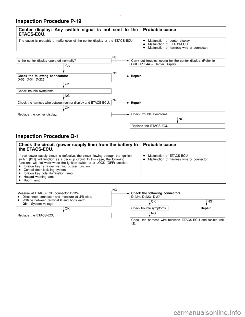
Inspection Procedure P-19
Center display: Any switch signal is not sent to the
ETACS-ECU.Probable cause
The cause is probably a malfunction of the center display or the ETACS-ECU.DMalfunction of center display
DMalfunction of ETACS-ECU
DMalfunction of harness wire or connector.
Ye s
NG
Repair
NG
Replace the ETACS-ECU.
OK
Replace the center display.Check trouble symptoms.
NG
Check the harness wire between center display and ETACS-ECU.NG
Repair
OK
Check trouble symptoms.
Check the following connectors:
D-06, D-31, D-226
Is the center display operated normally?NoCarry out troubleshooting for the center display. (Refer to
GROUP 54A – Center Display.)
Inspection Procedure Q-1
Check the circuit (power supply line) from the battery to
the ETACS-ECU.Probable cause
If that power supply circuit is defective, the circuit flowing through the ignition
switch (IG1) will function as a back-up circuit. In this case, the following
functions will not work when the ignition switch is at LOCK (OFF) position.
DIgnition key reminder warning buzzer function
DCentral door lock ing system
DIgnition key hole illumination lamp
DHazard warninglamp
DRoom lampDMalfunction of ETACS-ECU
DMalfunction of harness wire or connector.
NG
NG
Repair
NG
Check the harness wire between ETACS-ECU and fusible link
(2).
OK
Replace the ETACS-ECU.
OK
Check trouble symptoms.
Check the following connectors:
D-224, D-223, D-27Measure at ETACS-ECU connector D-224.
DDisconnect connector and measure at J/B side.
DVoltage between terminal 6 and body earth.
OK:System voltage
www.WorkshopManuals.co.uk
Purchased from www.WorkshopManuals.co.uk
Page 1810 of 1839
HEATER, AIR CONDITIONER AND VENTILATION -Troubleshooting
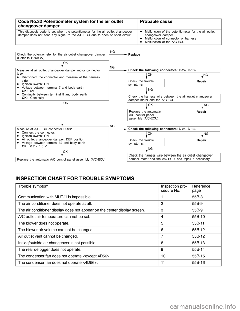
Code No.32 Potentiometer system for the air outlet
changeover damperProbable cause
This diagnosis code is set when the potentiometer for the air outlet changeover
damper does not send any signal to the A/C-ECU due toopen orshort circuit.DMalfunction of the potentiometer for the air outlet
changeover damper
DMalfunction of connector or harness
DMalfunction of the A/C-ECU
NG
Repair
NG
Repair
NG
Check the harness wire between the air outlet changeover
damper motor and the A/C-ECU, and repair if necessary.OK
Replace the automatic A/C control panelassembly (A/C-ECU).
NG
Repair
OK
Replace the automatic
A/C control panel
assembly (A/C-ECU).
OK
Check the trouble
symptoms.
OK
Measure at A/C-ECU connector D-132.
DConnect the connector.
DIgnition switch: ON
DAir outlet changeover damper: DEF position
DVoltage between terminal 32 and body earth
OK:0.7 - 1.3 VNGCheck the following connectors:D-24, D-132
NG
Check the harness wire between the air outlet changeover
damper motor and the A/C-ECU.
OK
Check the trouble
symptoms.
OK
Measure at air outlet changeover damper motor connector
D-24.
DDisconnect the connector and measure at the harness
side.
DIgnition switch: ON
DVoltage between terminal 7 and body earth
OK:5V
DContinuity between terminal 5 and body earth
OK:ContinuityNGCheck the following connectors:D-24, D-132
Check the potentiometer for the air outlet changeover damper
(Refer to P.55B-27).NG
Replace
INSPECTION CHART FOR TROUBLE SYMPTOMS
Trouble symptomInspection pro-
cedure No.Reference
page
Communication with MUT-IIis impossible.155B-8
The air conditioner does not operate at all.255B-9
The air conditioner display does not appear on the center display screen.355B-9
A/C outlet air temperature can not be set.455B-10
The blower does not operate.555B-11
The blower air volume can not be changed.655B-12
Air outlet vent cannot be changed.755B-12
Inside/outside air changeover is not possible.855B-13
The rear defogger does not operate.955B-14
The condenser fan does not operate
The condenser fan does not operate <4D56>.1155B-16
www.WorkshopManuals.co.uk
Purchased from www.WorkshopManuals.co.uk
Page 1812 of 1839
HEATER, AIR CONDITIONER AND VENTILATION -Troubleshooting
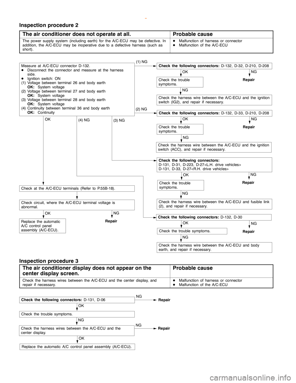
Inspection procedure 2
The air conditioner does not operate at all.
Probable cause
The power supply system (including earth) for the A/C-ECU may be defective. In
addition, the A/C-ECU may be inoperative due to a defective harness (such as
short).DMalfunction of harness or connector
DMalfunction of the A/C-ECU
NG
Repair
NG
Check the harness wire between the A/C-ECU and the ignition
switch (IG2), and repair if necessary.
NG
Repair
NG
Check the harness wire between the A/C-ECU and the ignition
switch (ACC), and repair if necessary.
NG
Repair
NG
Check the harness wire between the A/C-ECU and fusible link
(2), and repair if necessary.
NG
Repair
NG
Check the harness wire between the A/C-ECU and body
earth, and repair if necessary.
OK
Replace the automatic
A/C control panel
assembly (A/C-ECU).
NG
Repair
Check circuit, where the A/C-ECU terminal voltage is
abnormal.
OK
Check at the A/C-ECU terminals (Refer to P.55B-18).
OK
Check the trouble symptoms.
Check the following connectors:D-132, D-30
(4) NG
OK
Check the trouble
symptoms.
Check the following connectors:
D-131, D-31, D-223, D-27
D-131, D-33, D-27
(3) NGOK
Check the trouble
symptoms.
Check the following connectors:D-132, D-33, D-210, D-208(2) NG
OK
Check the trouble
symptoms.
Measure at A/C-ECU connector D-132.
DDisconnect the connector and measure at the harness
side.
DIgnition switch: ON
(1) Voltage between terminal 26 and body earth
OK:System voltage
(2) Voltage between terminal 27 and body earth
OK:System voltage
(3) Voltage between terminal 28 and body earth
OK:System voltage
(4) Continuity between terminal 36 and body earth
OK:Continuity(1) NGCheck the following connectors:D-132, D-32, D-210, D-208
Inspection procedure 3
The air conditioner display does not appear on the
center display screen.
Probable cause
Check the harness wires between the A/C-ECU and the center display, and
repair if necessary.DMalfunction of harness or connector
DMalfunction of the A/C-ECU
OK
Replace the automatic A/C control panelassembly (A/C-ECU).
NG
Check the harness wires between the A/C-ECU and the
center display.NG
Repair
OK
Check the trouble symptoms.
Check the following connectors:D-131, D-06NG
Repair
www.WorkshopManuals.co.uk
Purchased from www.WorkshopManuals.co.uk
Page 1813 of 1839
HEATER, AIR CONDITIONER AND VENTILATION -Troubleshooting
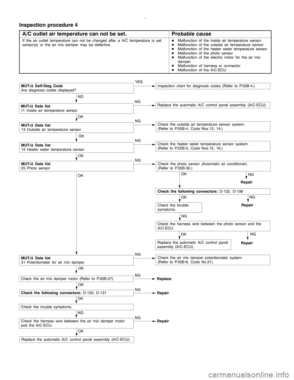
Inspection procedure 4
A/C outlet air temperature can not be set.
Probable cause
If the air outlet temperature can not be changed after a A/C temperature is set,
sensor(s) or the air mix damper may be defective.DMalfunction of the inside air temperature sensor
DMalfunction of the outside air temperature sensor
DMalfunction of the heater water temperature sensor
DMalfunction of the photo sensor
DMalfunction of the electric motor for the air mix
damper
DMalfunction of harness or connector
DMalfunction of the A/C-ECU
NG
Repair
NG
Repair
OK
Replace the automatic A/C control panelassembly (A/C-ECU).
OK
MUT-
IIData list
31 Potentiometer for air mix damperNGCheck the air mix damper potentiometer system
(Refer to P.55B-6, Code No.31).
NG
Check the harness wire between the photo sensor and the
A/C-ECU.
OK
Check the trouble
symptoms.
OK
Check the following connectors:D-132, D-106
OK
MUT-
IIData list
25 Photo sensorNGCheck the photo sensor (Automatic air conditioner).
(Refer to P.55B-30.)
OK
MUT-
IIData list
15 Heater water temperature sensorNGCheck the heater water temperature sensor system.
(Refer to P.55B-5, Code Nos.15, 16.)
OK
MUT-
IIData list
13 Outside air temperature sensorNGCheck the outside air temperature sensor system.
(Refer to P.55B-4, Code Nos.13, 14.)
NO
MUT-
IIData list
11 Inside air temperature sensorNGReplace the automatic A/C control panelassembly (A/C-ECU).
MUT-
IISelf-Diag Code
Are diagnosis codes displayed?YESInspection chart for diagnosis codes (Refer to P.55B-4.)
NG
Repair OKReplace the automatic A/C control panel
assembly (A/C-ECU).
NG
Check the harness wire between the air mix damper motor
and the A/C-ECU.NG
Repair
OK
Check the trouble symptoms.
OK
Check the following connectors:D-130, D-131NG
Repair
Check the air mix damper motor (Refer to P.55B-27).NG
Replace OK
www.WorkshopManuals.co.uk
Purchased from www.WorkshopManuals.co.uk
Page 1820 of 1839

HEATER, AIR CONDITIONER AND VENTILATION -Troubleshooting
DATA LIST REFERENCE TABLE
Item No.Check itemInspection contents
11Inside air temperature sensorIgnition switch: ONInside air temperature and tempera-
ture displayed on the MUT-IIare
identical.
13Outside air temperature sen-
sorIgnition switch: ONOutside air temperature and tem-
perature displayed on the MUT-II
are identical.
15Heater water temperature
sensorIgnition switch: ONHeater core surface temperature
and temperature displayed on the
MUT-IIare identical.
21Air thermo sensorIgnition switch: ONEvaporator outlet temperature and
temperature displayed on the MUT-
IIare identical.
25Photo sensorIgnition switch: ONAmount of incident light is propor-
tional to voltage displayed on the
MUT-II.
31Potentiometer for the air mix
damperIgnition switch: ON
Damper position: MAX HOTOpening angle: Approximately
100%
Ignition switch: ON
Damper position: MAX COOLOpening angle: Approximately 0%
32Potentiometer for the air
outlet changeover damperIgnition switch: ON
Damper position: FACEOpening angle: Approximately 0%
Ignition switch: ON
Damper position:FOOTOpening angle: Approximately 60%
Ignition switch: ON
Damper position: FOOT/DEFOpening angle: Approximately 80%
Ignition switch: ON
Damper position: DEFOpening angle: Approximately
100%
ACTUATOR TEST TABLE
Item No.Check itemDrive Contents
01Blower motorStopped
02Low speed
03Medium speed
04High speed
05Electric motor for the air mix damperOpening angle: Approximately 0%
06Opening angle: Approximately 50%
07Opening angle: Approximately 100%
08Electric motor for the air outlet changeoverFACE
09damperFOOT
10DEF
11Compressor ON/OFFOFF
12ON
13Inside/outside air changeover damper motorOutside air
14Inside air
www.WorkshopManuals.co.uk
Purchased from www.WorkshopManuals.co.uk
Page 1822 of 1839

HEATER, AIR CONDITIONER AND VENTILATION -Troubleshooting
Termi-
nal No.Normal condition Check conditions Check item
15Rear defoggerRear defogger: OFFSystem voltage
Rear defogger: ON1.5 V or less
16Multi center display unit communication
lineIgnition switch: ONHi: 4 - 5 V
Lo: 0 - 1 V
17Multi center display unit communication
lineIgnition switch: ONHi: 4 - 5 V
Lo: 0 - 1 V
18Multi center display unit communication
line shieldAt all times0V
19Diagnosis outputIgnition switch: ONA voltmeter needle
fluctuates between 0
and 12 V.
20Input from A/C compressor relayWhen the A/C is off.0V
When the A/C is in operation
(When compressor is operating)System voltage
21Power supply to potentiometerAt all times5V
22Input from outside air temperature
sensorSensor temperature: 25
_C (1.7 kW)1.9 V
23Input from heater water temperature
sensorSensor temperature: 25
_C(5kW)2.8 V
24Input from potentiometer for air mix
damperWhen the damper flap is moving to the
MAX HOT position.0.7 - 1.3 V
25Power supply to illuminationLighting switch: ONSystem voltage
26Power supply to ignition switch (IG2)Ignition switch: ONSystem voltage
27Power supply to ignition switch (ACC)Ignition switch: ACCSystem voltage
28Backup power supplyAt all timesSystem voltage
29Earth to sensor and potentiometerAt all times0V
30Input from air thermo sensorSensor temperature: 25
_C (1.5 kW)2.2 V
31Photo sensor (+)During 800 kcal/m2-h1V
32Input from potentiometer for the air
outlet changeover damperWhen the damper flap is moving to the
DEF position.0.7 - 1.3 V
33Diagnosis inputIgnition switch: ON0V
34Compressor lock signal (ignition signal)Engine speed: 3 000 r/min0.3 - 3.0
35Illumination earthAt all timesContinuity
36EarthAt all timesContinuity
CHECK AT ENGINE-A/T-ECU OR ENGINE-ECU TERMINALS
Refer to GROUP 13A – Troubleshooting
www.WorkshopManuals.co.uk
Purchased from www.WorkshopManuals.co.uk