2000 MITSUBISHI MONTERO display
[x] Cancel search: displayPage 262 of 1839
GDI -Troubleshooting
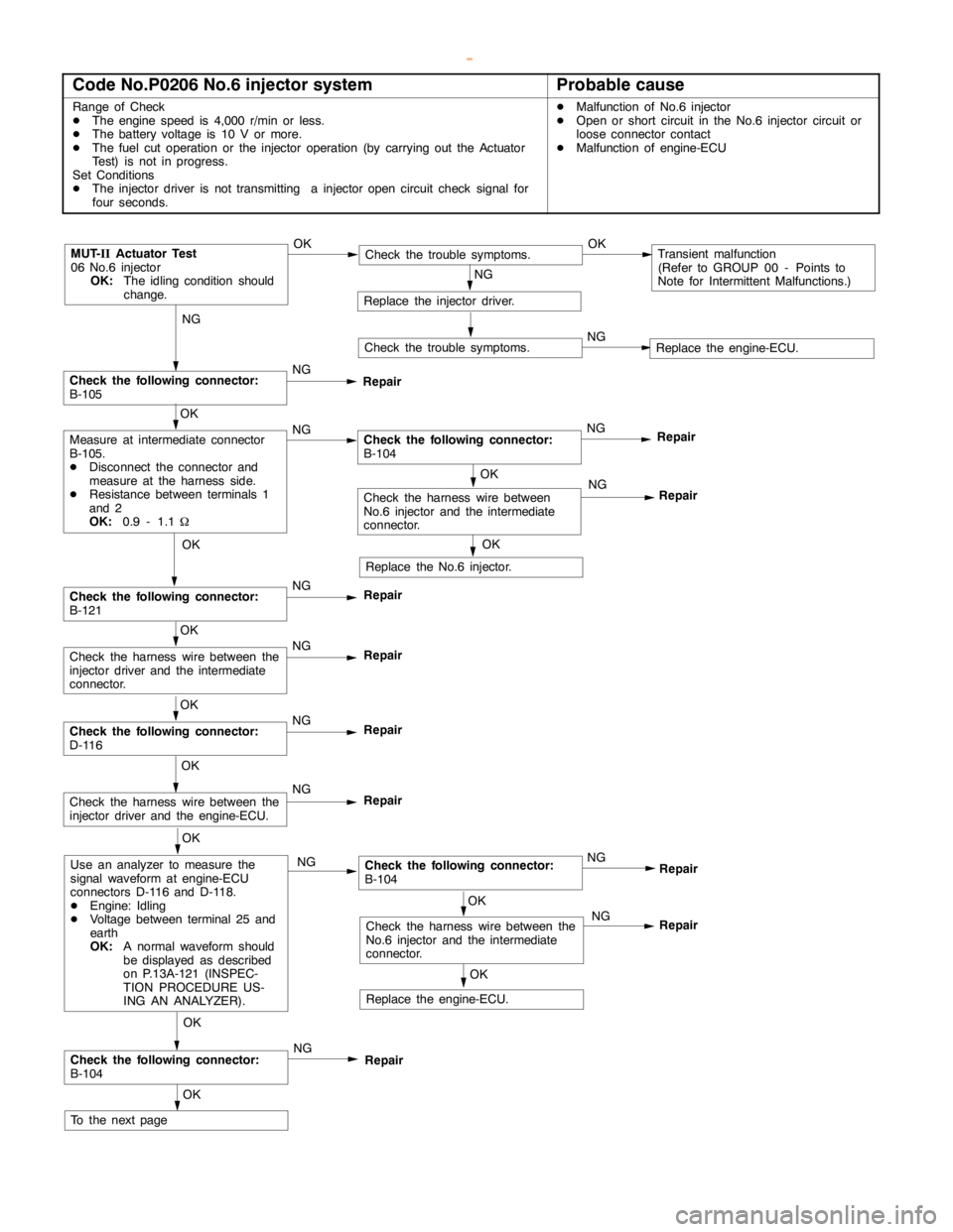
Code No.P0206 No.6 injector systemProbable cause
Range of Check
DThe enginespeed is 4,000 r/min or less.
DThe battery voltage is 10 V or more.
DThe fuel cut operation or the injector operation (by carrying out the Actuator
Test) is not in progress.
Set Conditions
DThe injector driver is not transmitting a injectoropencircuit check signal for
four seconds.DMalfunction of No.6 injector
DOpen or short circuit in the No.6 injector circuit or
loose connector contact
DMalfunction of engine-ECU
NG
Check the following connector:
B-105NG
Repair
OK
NG
Repair
MUT-
IIActuator Test
06 No.6 injector
OK:
The idling condition should
change.OKCheck the trouble symptoms.OKTransient malfunction
(Refer to GROUP 00 - Points to
Note for Intermittent Malfunctions.)
NG
Replace the injector driver.
Check the trouble symptoms.NGReplace the engine-ECU.
OK
Measure at intermediate connector
B-105.
DDisconnect the connector and
measure at the harness side.
DResistance between terminals 1
and 2
OK:
0.9 - 1.1WNGCheck the following connector:
B-104NG
Repair
OK
Replace the No.6 injector.
OK
Check the following connector:
B-121NG
Repair
OK
Check the harness wire between the
injector driver and the intermediate
connector.NG
Repair
OK
Check the following connector:
D-116NG
Repair
OK
Check the harness wire between the
injector driver and the engine-ECU.NG
Repair
OK
Use an analyzer to measure the
signal waveform at engine-ECU
connectors D-116 and D-118.
DEngine: Idling
DVoltage between terminal 25 and
earth
OK:
A normal waveform should
be displayed as described
on P.13A-121 (INSPEC-
TION PROCEDURE US-
ING AN ANALYZER).NGCheck the following connector:
B-104
OK
Check the following connector:
B-104NG
Repair
OK
To the nextpageNG
OK
OK
Check the harness wire between the
No.6 injector and the intermediate
connector.NG
Replace the engine-ECU.
Repair
Repair
Check the harness wire between
No.6 injector and the intermediate
connector.
www.WorkshopManuals.co.uk
Purchased from www.WorkshopManuals.co.uk
Page 268 of 1839
GDI -Troubleshooting
OK
Check the harness wire between the
engine-ECU and the intermediate
connector.NG
Repair
OK
Check the following connector:
D-116NG
Repair
OK
Check the harness wire between the
ignition coil connector for a defective
cylinder and the intermediate
connector.NG
Repair
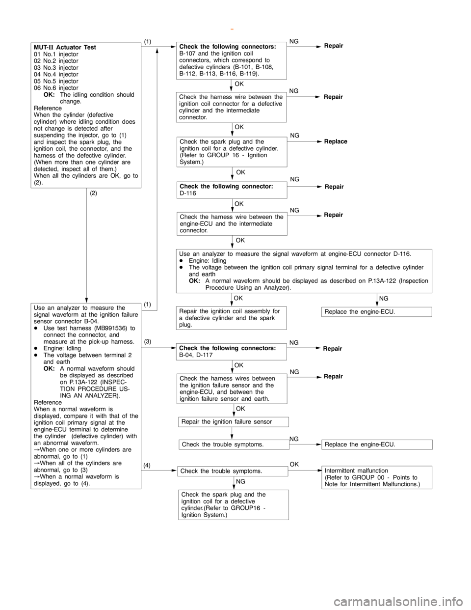
MUT-
IIActuator Test
01 No.1 injector
02 No.2 injector
03 No.3 injector
04 No.4 injector
05 No.5 injector
06 No.6 injector
OK:
The idling condition should
change.
Reference
When the cylinder (defective
cylinder) whereidling conditiondoes
not change is detected after
suspending the injector, go to (1)
and inspect the spark plug, the
ignition coil, the connector, and the
harness of the defective cylinder.
(When more than one cylinder are
detected, inspect all of them.)
When all the cylinders are OK, go to
(2).(1)Check the following connectors:
B-107 and the ignition coil
connectors, which correspond to
defective cylinders (B-101, B-108,
B-112, B-113, B-116, B-119).NG
Repair
OK
Check the sparkplug and the
ignition coil for a defective cylinder.
(Refer to GROUP 16 - Ignition
System.)NG
Replace
OK
Use an analyzer to measure the signal waveform at engine-ECU connector D-116.
DEngine: Idling
DThe voltage between the ignition coil primary signal terminal for a defective cylinder
and earth
OK:
A normal waveform should be displayed as described on P.13A-122 (Inspection
Procedure Using an Analyzer).
OK
Repair the ignition coil assembly for
a defective cylinder and the spark
plug.
NG
Replace the engine-ECU.
(2)
Use an analyzer to measure the
signal waveform at the ignition failure
sensor connector B-04.
DUse test harness (MB991536) to
connect the connector, and
measure at the pick-up harness.
DEngine: Idling
DThe voltage between terminal 2
and earth
OK:
A normal waveform should
be displayed as described
on P.13A-122 (INSPEC-
TION PROCEDURE US-
ING AN ANALYZER).
Reference
When a normal waveform is
displayed, compare it with that of the
ignition coil primary signal at the
engine-ECU terminal to determine
the cylinder (defective cylinder) with
an abnormal waveform.
®When one or more cylinders are
abnormal, go to (1)
®When all of the cylinders are
abnormal, go to (3)
®When a normal waveform is
displayed, go to (4).(3)
Check the following connectors:
B-04, D-117NG
Repair
OK
Check the harness wires between
the ignition failure sensor and the
engine-ECU, and between the
ignition failure sensor and earth.NG
Repair
OK
Repair the ignition failure sensor
Check the trouble symptoms.NGReplace the engine-ECU.
(4)Check the trouble symptoms.OKIntermittent malfunction
(Refer to GROUP 00 - Points to
Note for Intermittent Malfunctions.)
NG
Check the sparkplug and the
ignition coil for a defective
cylinder.(Refer to GROUP16 -
Ignition System.)
(1)
www.WorkshopManuals.co.uk
Purchased from www.WorkshopManuals.co.uk
Page 271 of 1839
GDI -Troubleshooting
OK
Check the harness wire between the
crankanglesensor and the
engine-ECU, and repair if necessary.
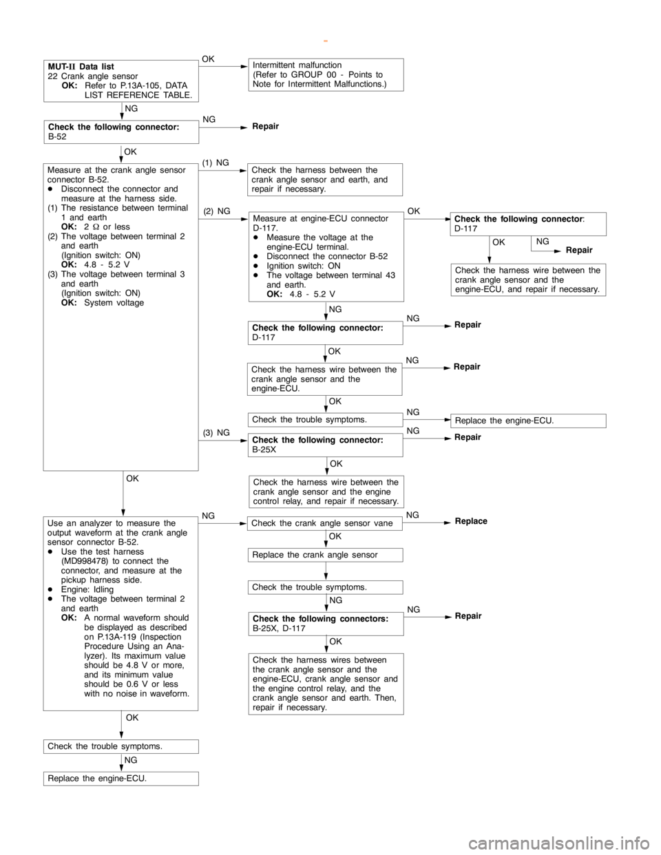
MUT-
IIData list
22 Crankanglesensor
OK:
Refer to P.13A-105, DATA
LIST REFERENCE TABLE.OKIntermittent malfunction
(Refer to GROUP 00 - Points to
Note for Intermittent Malfunctions.)
OK
Measure at the crankanglesensor
connector B-52.
DDisconnect the connector and
measure at the harness side.
(1) The resistance between terminal
1 and earth
OK:
2Wor less
(2) The voltage between terminal 2
and earth
(Ignition switch: ON)
OK:
4.8 - 5.2 V
(3) The voltage between terminal 3
and earth
(Ignition switch: ON)
OK:
System voltage(1) NGCheck the harness between the
crankanglesensor and earth, and
repair if necessary.
NG
Repair
NG
Check the following connector:
D-117NG
Repair
NG
Check the following connector:
B-52NG
Repair
(2) NGMeasure at engine-ECU connector
D-117.
DMeasure the voltage at the
engine-ECU terminal.
DDisconnect the connector B-52
DIgnition switch: ON
DThe voltage between terminal 43
and earth.
OK:
4.8 - 5.2 VOKCheck the following connector
:
D-117
Check the following connector:
B-25XNG
Repair
OK
Check the harness wire between the
crankanglesensor and the
engine-ECU.NG
Repair
OK
Check the trouble symptoms.NGReplace the engine-ECU.
(3) NG
OK
Check the harness wire between the
crankanglesensor and theengine
control relay, and repair if necessary.OK
Use an analyzer to measure the
output waveform at the crankangle
sensor connector B-52.
DUse the test harness
(MD998478) to connect the
connector, and measure at the
pickup harness side.
DEngine: Idling
DThe voltage between terminal 2
and earth
OK:
A normal waveform should
be displayed as described
on P.13A-119 (Inspection
Procedure Using an Ana-
lyzer). Its maximum value
should be 4.8 V or more,
and its minimumvalue
should be 0.6 V or less
with no noise in waveform.NGCheck the crankanglesensor vaneNG
Replace
OK
Replace the crankanglesensor
Check the trouble symptoms.
NG
Check the following connectors:
B-25X, D-117NG
Repair
OK
Check the harness wires between
the crankanglesensor and the
engine-ECU, crankanglesensor and
the engine controlrelay, and the
crankanglesensor and earth. Then,
repair if necessary.
OK
Check the trouble symptoms.
NG
Replace the engine-ECU.
www.WorkshopManuals.co.uk
Purchased from www.WorkshopManuals.co.uk
Page 273 of 1839
GDI -Troubleshooting
OK
Check the harness wire between the
intermediate connector and the
engine-ECU, and repair if necessary.NG
Repair
NG
NG
Repair
NG
Repair
(2) NGMeasure at engine-ECU connector
D-117.
DMeasure the voltage at the
engine-ECU terminal.
DDisconnect connector B-110.
DIgnition switch: ON
DThe voltage between terminal 50
and earth
OK:
4.8 - 5.2 VOKCheck the following connector
:
D-117
Check the harness wire between the
intermediate connector and earth,
and repair if necessary.
OK
Check the harness wire between the
intermediate connector and the
engine controlrelay, and repair if
necessary.
(3) NG
OK
Measure at intermediate connector
B-110
DDisconnect the connector and
measure at the harness side.
(1) The voltage between terminal 1
and earth
(Ignition switch: ON)
OK:
System voltage
(2) The voltage between terminal 2
and earth
(Ignition switch: ON)
OK:
4.8 - 5.2 V
(3) The resistance between terminal
3 and earth
OK:
2Wor less(1) NGCheck the following connector:
B-25XNG
Repair
OK
Replace the camshaft position
sensor
Check the trouble symptoms.
OK
NG
Repair
OK
Check the harness wires between the intermediate connector and the engine-ECU, the
intermediate connector and theengine controlrelay, and the intermediate connector and
earth. Then, repair if necessary.
NG
Replace the engine-ECU.
OK
Check the harness wire between the
intermediate connector and the
engine-ECU.NG
Repair
OK
Use an analyzer to measure the
output waveform at intermediate
connector B-110.
DUse test harness (MB991658) to
connect the connector, and
measure at the pick-up harness.
DEngine: Idling
DThe voltage between terminal 2
and earth
OK:
A normal waveform should
be displayed as described
on P.13A-119 (Inspection
Procedure Using an Ana-
lyzer), its maximum value
should be 4.8 V or more,
and its minimumvalue
should be 0.6 V or less
with no noise in waveform.(1) NGCheck the following connector:
B-109NG
Repair
OK
Check the harness wire between the
camshaft position sensor and the
intermediate connector.NG
Repair
NG
Check the camshaft position sensing
cylinderNG
OK
Check the trouble symptoms.Intermittent malfunction
(Refer to GROUP 00 - Points to Note for Intermittent Malfunctions.)
OK
Check the trouble symptoms.NGReplace the engine-ECU.
Replace
OK
Check the following connector:
B-110
Check the following connector:
D-117
Check the following connectors:
B-25X, D-117
www.WorkshopManuals.co.uk
Purchased from www.WorkshopManuals.co.uk
Page 277 of 1839
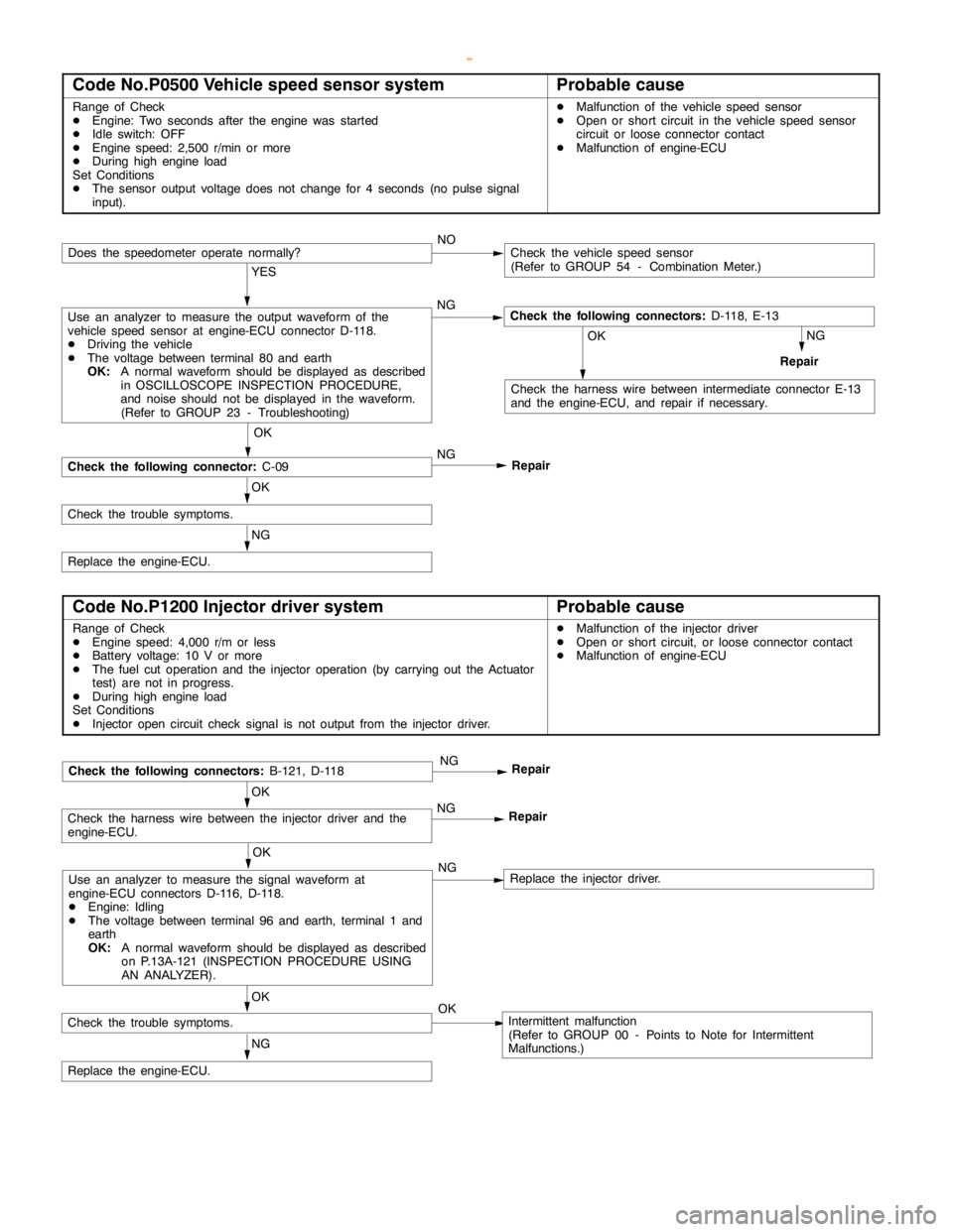
GDI -Troubleshooting
Code No.P0500 Vehicle speed sensor systemProbable cause
Range of Check
DEngine: Two seconds after theengine wasstarted
DIdle switch: OFF
DEngine speed: 2,500 r/min or more
DDuring high engine load
Set Conditions
DThe sensor output voltage does not change for 4 seconds (no pulse signal
input).DMalfunction of the vehicle speed sensor
DOpen or short circuit in the vehicle speed sensor
circuit or loose connector contact
DMalfunction of engine-ECU
NOCheck the vehicle speed sensor
(Refer to GROUP 54 - Combination Meter.)
YES
Use an analyzer to measure the output waveform of the
vehicle speed sensor at engine-ECU connector D-118.
DDriving the vehicle
DThe voltage between terminal 80 and earth
OK:
A normal waveform should be displayed as described
in OSCILLOSCOPE INSPECTION PROCEDURE,
and noise should not be displayed in the waveform.
(Refer to GROUP 23 - Troubleshooting)NGCheck the following connectors:
D-118, E-13
NG
Repair
OK
Check the harness wire between intermediate connector E-13
and the engine-ECU, and repair if necessary.
OK
Check the following connector:
C-09NG
Repair
OK
Check the trouble symptoms.
NG
Replace the engine-ECU.
Does the speedometer operate normally?
Code No.P1200 Injector driver systemProbable cause
Range of Check
DEngine speed: 4,000 r/m or less
DBattery voltage: 10 V or more
DThe fuel cut operation and the injector operation (by carrying out the Actuator
test) are not in progress.
DDuring high engine load
Set Conditions
DInjector opencircuit check signal is not output from the injector driver.DMalfunction of the injector driver
DOpen or short circuit, or loose connector contact
DMalfunction of engine-ECU
OK
Use an analyzer to measure the signal waveform at
engine-ECU connectors D-116, D-118.
DEngine: Idling
DThe voltage between terminal 96 and earth, terminal 1 and
earth
OK:
A normal waveform should be displayed as described
on P.13A-121 (INSPECTIONPROCEDURE USING
AN ANALYZER).NGReplace the injector driver.
OK
Check the harness wire between the injector driver and the
engine-ECU.NG
Repair
NG
Replace the engine-ECU.
Check the following connectors:
B-121, D-118NG
Repair
OK
Check the trouble symptoms.OKIntermittent malfunction
(Refer to GROUP 00 - Points to Note for Intermittent
Malfunctions.)
www.WorkshopManuals.co.uk
Purchased from www.WorkshopManuals.co.uk
Page 285 of 1839
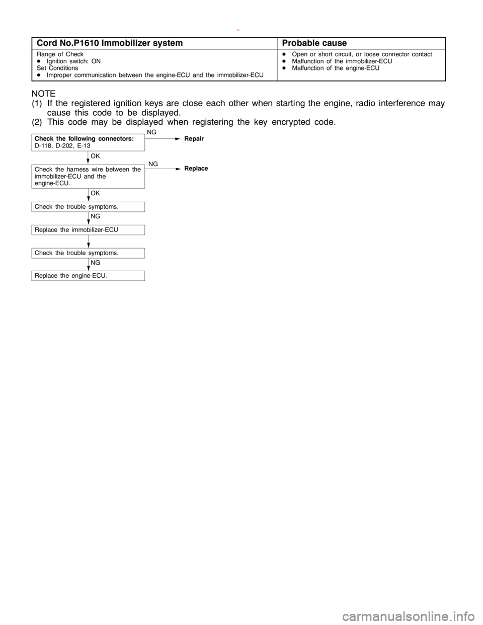
GDI -Troubleshooting
Cord No.P1610 Immobilizer systemProbable cause
Range of Check
DIgnition switch: ON
Set Conditions
DImproper communication between the engine-ECU and the immobilizer-ECUDOpen or short circuit, or loose connector contact
DMalfunction of the immobilizer-ECU
DMalfunction of the engine-ECU
NOTE
(1) If the registered ignition keys are close each other when starting the engine, radio interference may
cause this code to be displayed.
(2) This code may be displayed when registering the key encrypted code.
NG
Replace the engine-ECU.
Check the trouble symptoms.
NG
Replace the immobilizer-ECU
OK
Check the trouble symptoms.
OK
Check the harness wire between the
immobilizer-ECU and the
engine-ECU.NG
Replace
Check the following connectors:
D-118, D-202, E-13NG
Repair
www.WorkshopManuals.co.uk
Purchased from www.WorkshopManuals.co.uk
Page 289 of 1839
GDI -Troubleshooting
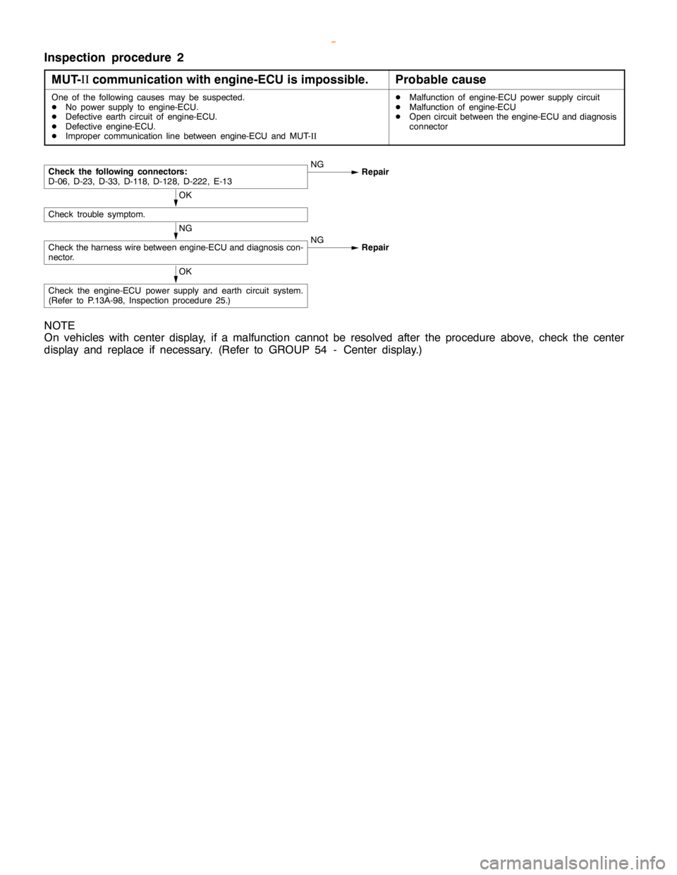
Inspection procedure 2
MUT-II
communication with engine-ECU is impossible.
Probable cause
One of the following causes may be suspected.
DNo power supply to engine-ECU.
DDefective earth circuit of engine-ECU.
DDefective engine-ECU.
DImproper communication line between engine-ECU and MUT-IIDMalfunction of engine-ECU power supply circuit
DMalfunction of engine-ECU
DOpen circuit between the engine-ECU and diagnosis
connector
NG
Check the harness wire between engine-ECU and diagnosis con-
nector.NG
Repair
OK
Check trouble symptom.
Check the following connectors:
D-06, D-23, D-33, D-118, D-128, D-222, E-13NG
Repair
OK
Check the engine-ECU power supply and earth circuit system.
(Refer to P.13A-98, Inspection procedure 25.)
NOTE
On vehicles with center display, if a malfunction cannot be resolved after the procedure above, check the center
display and replace if necessary. (Refer to GROUP 54 - Center display.)
www.WorkshopManuals.co.uk
Purchased from www.WorkshopManuals.co.uk
Page 290 of 1839
GDI -Troubleshooting
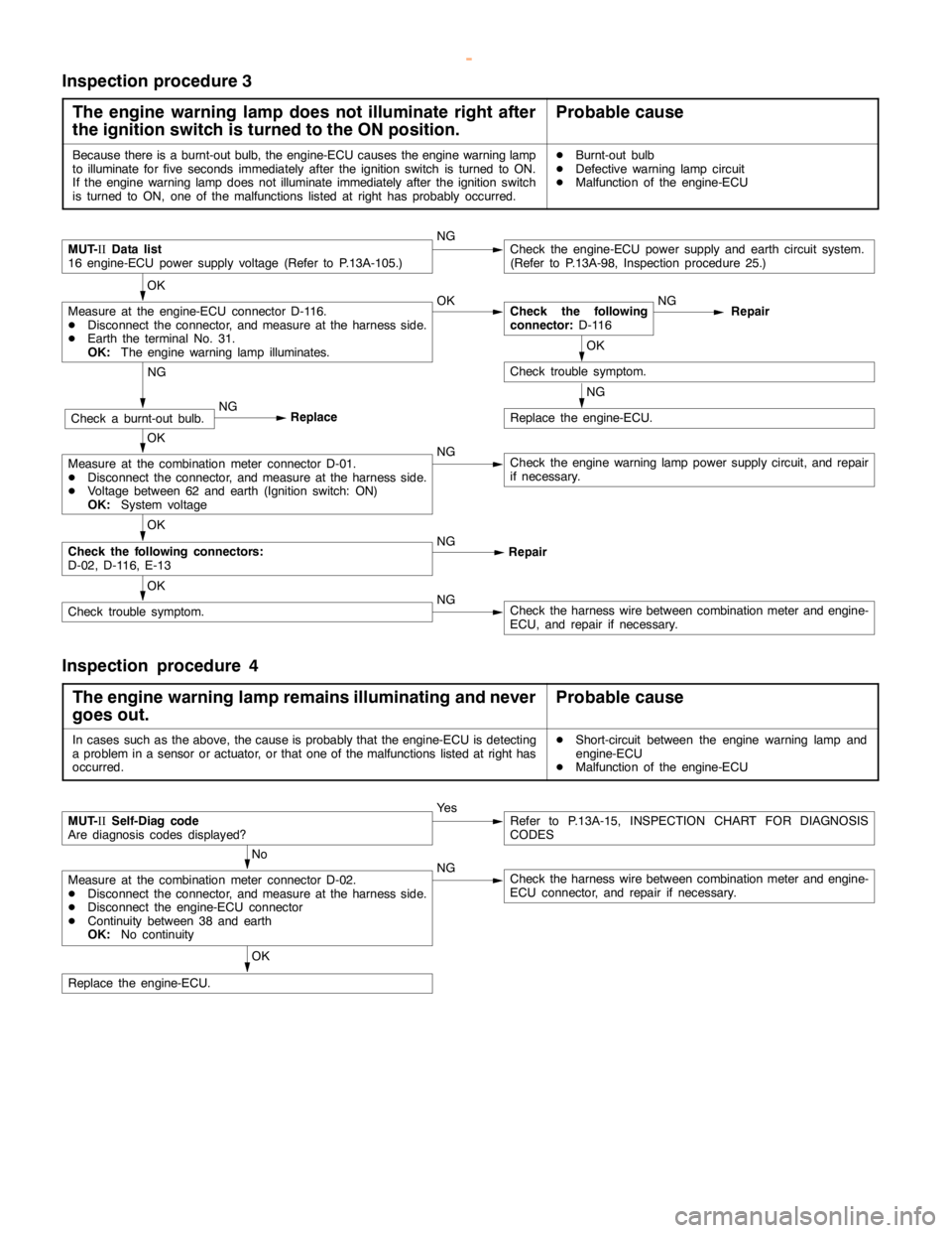
Inspection procedure 3
The engine warning lamp does not illuminate right after
the ignition switch is turned to the ON position.
Probable cause
Because there is a burnt-out bulb, the engine-ECU causes theengine warning lamp
to illuminate forfive seconds immediately after the ignition switch is turned to ON.
If the engine warning lampdoes notilluminate immediately after the ignitionswitch
is turned to ON, one of the malfunctions listed at right has probably occurred.DBurnt-out bulb
DDefective warninglampcircuit
DMalfunction of the engine-ECU
MUT-
IIData list
16 engine-ECU power supply voltage (Refer to P.13A-105.)NGCheck the engine-ECU power supply and earth circuit system.
(Refer to P.13A-98, Inspection procedure 25.)
OK
Measure at the engine-ECU connector D-116.
DDisconnect the connector, and measure at the harness side.
DEarth the terminal No. 31.
OK:
The engine warning lamp illuminates.OKCheck the following
connector:
D-116NG
Repair
OK
Check trouble symptom.
NG
Replace the engine-ECU.
NG
Check a burnt-out bulb.NG
Replace
OK
Measure at the combination meter connector D-01.
DDisconnect the connector, and measure at the harness side.
DVoltage between 62 and earth (Ignition switch: ON)
OK:
System voltageNGCheck theengine warning lamppower supply circuit, and repair
if necessary.
OK
Check the following connectors:
D-02, D-116, E-13NG
Repair
OK
Check trouble symptom.NGCheck the harness wire between combination meter and engine-
ECU, and repair if necessary.
Inspection procedure 4
The engine warning lamp remains illuminating and never
goes out.
Probable cause
In cases such as the above, the cause is probably that the engine-ECU is detecting
a problem in a sensor or actuator, or that one of the malfunctions listed at right has
occurred.DShort-circuit between the engine warning lamp and
engine-ECU
DMalfunction of the engine-ECU
MUT-
IISelf-Diag code
Are diagnosis codes displayed?Ye sRefer to P.13A-15, INSPECTION CHART FOR DIAGNOSIS
CODES
No
Measure at the combination meter connector D-02.
DDisconnect the connector, and measure at the harness side.
DDisconnect the engine-ECU connector
DContinuity between 38 and earth
OK:
No continuityNGCheck the harness wire between combination meter and engine-
ECU connector, and repair if necessary.
OK
Replace the engine-ECU.
www.WorkshopManuals.co.uk
Purchased from www.WorkshopManuals.co.uk