2000 MITSUBISHI MONTERO fuel
[x] Cancel search: fuelPage 304 of 1839
GDI -Troubleshooting
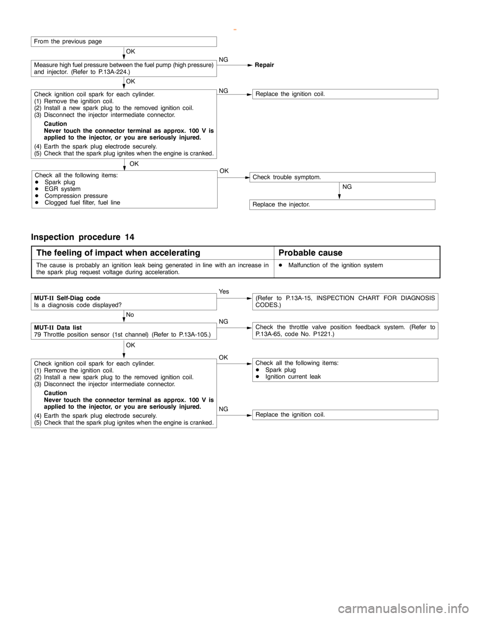
From the previouspage
OK
Measure high fuelpressure between the fuelpump (highpressure)
and injector. (Refer to P.13A-224.)NG
Repair
OK
Check ignition coil spark for each cylinder.
(1) Remove the ignition coil.
(2) Install a new sparkplug to the removed ignitioncoil.
(3) Disconnect the injector intermediate connector.
Caution
Never touch the connector terminal as approx. 100 V is
applied to the injector, or you are seriously injured.
(4) Earth the sparkplug electrodesecurely.
(5) Check that the sparkplug igniteswhen theengine iscranked.NGReplace the ignition coil.
OK
Check all the following items:
DSparkplug
DEGR system
DCompression pressure
DClogged fuel filter, fuel lineNGCheck trouble symptom.
Replace the injector.
OK
Inspection procedure 14
The feeling of impact when accelerating
Probable cause
The cause is probably an ignition leakbeing generated in linewith an increase in
the sparkplug request voltage during acceleration.DMalfunction of the ignition system
NGReplace the ignition coil.
MUT-
IISelf-Diag code
Is a diagnosis code displayed?Ye s(Refer to P.13A-15, INSPECTION CHART FOR DIAGNOSIS
CODES.)
No
MUT-
IIData list
79 Throttle position sensor (1st channel) (Refer to P.13A-105.)NGCheck the throttle valve position feedback system. (Refer to
P.13A-65, code No. P1221.)
OK
Check ignition coil spark for each cylinder.
(1) Remove the ignition coil.
(2) Install a new sparkplug to the removed ignitioncoil.
(3) Disconnect the injector intermediate connector.
Caution
Never touch the connector terminal as approx. 100 V is
applied to the injector, or you are seriously injured.
(4) Earth the sparkplug electrodesecurely.
(5) Check that the sparkplug igniteswhen theengine iscranked.OKCheck all the following items:
DSparkplug
DIgnition current leak
www.WorkshopManuals.co.uk
Purchased from www.WorkshopManuals.co.uk
Page 305 of 1839

GDI -Troubleshooting
Inspection procedure 15
The feeling of impact when decelerating
Probable cause
The cause is probably insufficient intake air due to a faulty electronic-controlled throttle
valve system.DMalfunction of the electronic-controlled throttle valve
system
MUT-
IISelf-Diag code
Is a diagnosis code displayed?Ye s(Refer to P.13A-15, INSPECTION CHART FOR DIAGNOSIS
CODES.)
No
MUT-
IIData list
79 Throttle position sensor (1st channel) (Refer to P.13A-105.)NGCheck the throttle valve position feedback system. (Refer to
P.13A-65, code No. P1221.)
OK
MUT-
IIData list
26 Acceleratorpedal positionswitch (Refer to P.13A-105.)NGCheck the acceleratorpedal positionswitch system. (Refer to
P.13A-100, Inspection procedure 28.)
OK
Clean around the throttle valve. (Refer to P.13A-220.)
Inspection procedure 16
Knocking
Probable cause
The cause is probably incorrect detonation control or improper heat range of the
spark plugs.DMalfunction of the detonation sensor
DImproper heat range of the spark plugs
MUT-
IISelf-Diag code
Is a diagnosis code displayed?Ye s(Refer to P.13A-15, INSPECTION CHART FOR DIAGNOSIS
CODES.)
No
Does knocking occur when the vehicle is driven with the detonation
sensor disconnected?
(At this time, use the MUT-IIto check whether the ignitiontiming
is retarded from when the detonation sensor connector is con-
nected.)NoCheck the detonation sensor system. (Refer to P.13A-56, code
No. P0325.)
Ye s
Check all the following items:
DSparkplug
DForeign material (such as water or kerosine) entered the fuel
lines
Inspection procedure 17
Run-on (dieseling)
Probable cause
The cause is probably fuel leak from injector(s)DMalfunction of the injector
Replace the injector.
www.WorkshopManuals.co.uk
Purchased from www.WorkshopManuals.co.uk
Page 306 of 1839
GDI -Troubleshooting
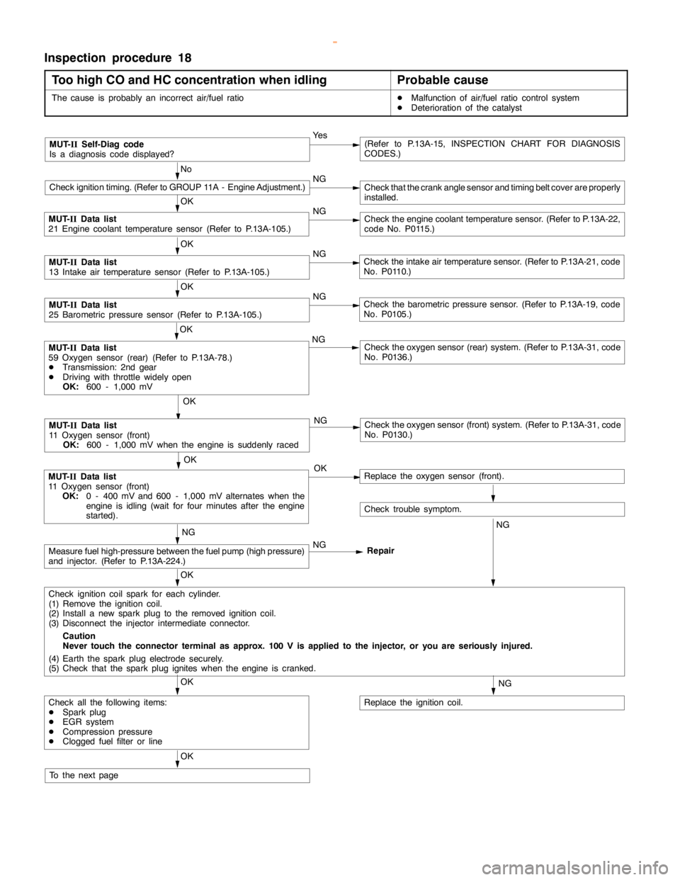
Inspection procedure 18
Too high CO and HC concentration when idling
Probable cause
The cause is probably an incorrect air/fuel ratioDMalfunction of air/fuel ratio control system
DDeterioration of the catalyst
MUT-
IISelf-Diag code
Is a diagnosis code displayed?Ye s(Refer to P.13A-15, INSPECTION CHART FOR DIAGNOSIS
CODES.)
No
Check ignition timing. (Refer to GROUP 11A - Engine Adjustment.)NGCheck that the crankanglesensor andtiming beltcover are properly
installed.
OK
MUT-
IIData list
21 Engine coolant temperature sensor (Refer to P.13A-105.)NGCheck theengine coolant temperaturesensor. (Refer to P.13A-22,
code No. P0115.)
OK
MUT-
IIData list
13 Intake air temperature sensor (Refer to P.13A-105.)NGCheck the intake air temperature sensor. (Refer to P.13A-21, code
No. P0110.)
OK
MUT-
IIData list
25 Barometric pressure sensor (Refer to P.13A-105.)NGCheck the barometric pressure sensor. (Refer to P.13A-19, code
No. P0105.)
OK
NG
Check the oxygen sensor (front) system. (Refer to P.13A-31, code
No. P0130.)
OK
MUT-
IIData list
11 Oxygen sensor (front)
OK:
0 - 400 mV and 600 - 1,000 mV alternates when the
engine is idling(wait for four minutes after theengine
started).OKReplace the oxygen sensor (front).
Check trouble symptom.
NGNG
Measure fuel high-pressure between the fuel pump (highpressure)
and injector. (Refer to P.13A-224.)NG
Repair
OK
Check ignition coil spark for each cylinder.
(1) Remove the ignition coil.
(2) Install a new sparkplug to the removed ignitioncoil.
(3) Disconnect the injector intermediate connector.
Caution
Never touch the connector terminal as approx. 100 V is applied to the injector, or you are seriously injured.
(4) Earth the sparkplug electrodesecurely.
(5) Check that the sparkplug igniteswhen theengine iscranked.
NG
Replace the ignition coil.
OK
Check all the following items:
DSparkplug
DEGR system
DCompression pressure
DClogged fuel filter or line
OK
To the nextpage
OK
MUT-
IIData list
59 Oxygen sensor (rear) (Refer to P.13A-78.)
DTransmission: 2nd gear
DDriving with throttle widelyopen
OK:
600 - 1,000 mVNGCheck the oxygen sensor (rear) system. (Refer to P.13A-31, code
No. P0136.)
MUT-
IIData list
11 Oxygen sensor (front)
OK:
600 - 1,000 mV when theengine is suddenlyraced
www.WorkshopManuals.co.uk
Purchased from www.WorkshopManuals.co.uk
Page 310 of 1839
GDI -Troubleshooting
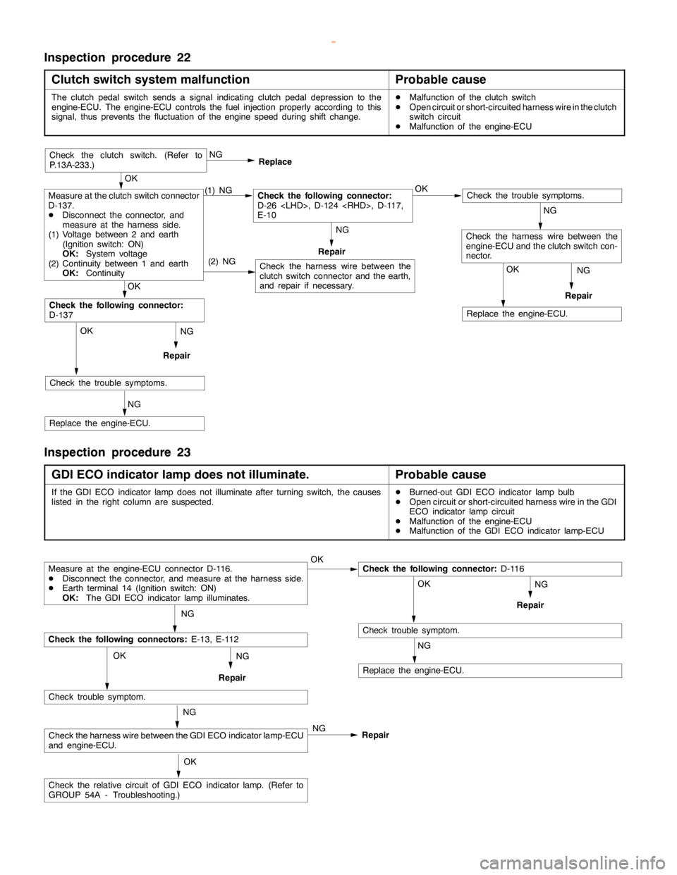
Inspection procedure 22
Clutch switch system malfunction
Probable cause
The clutchpedalswitch sends a signal indicating clutchpedal depression to the
engine-ECU. The engine-ECU controls the fuel injection properly according to this
signal, thus prevents the fluctuation of theenginespeed during shift change.DMalfunction of the clutch switch
DOpen circuit or short-circuited harness wire in the clutch
switch circuit
DMalfunction of the engine-ECU
NG
Repair
NG
Repair
OK
Replace the engine-ECU.
(2) NG
OK
Check the trouble symptoms.
NG
Replace the engine-ECU.
OK
Check the following connector:
D-137
Check the harness wire between the
clutch switch connector and the earth,
and repair if necessary.
Check the trouble symptoms.
Check the harness wire between the
engine-ECU and the clutch switch con-
nector.
Measure at the clutch switch connector
D-137.
DDisconnect the connector, and
measure at the harness side.
(1) Voltage between 2 and earth
(Ignition switch: ON)
OK:
System voltage
(2) Continuity between 1 and earth
OK:
Continuity(1) NGCheck the following connector:
D-26
E-10OK NG
Replace
Repair
OK
Check the clutch switch. (Refer to
P.13A-233.)
NG
NG
Inspection procedure 23
GDI ECO indicator lamp does not illuminate.
Probable cause
If the GDI ECO indicator lampdoes notilluminate after turningswitch, the causes
listed in the right column are suspected.DBurned-out GDI ECO indicator lamp bulb
DOpen circuit or short-circuited harness wire in the GDI
ECO indicator lampcircuit
DMalfunction of the engine-ECU
DMalfunction of the GDI ECO indicator lamp-ECU
NG
Repair
Measure at the engine-ECU connector D-116.
DDisconnect the connector, and measure at the harness side.
DEarth terminal 14 (Ignition switch: ON)
OK:
The GDI ECO indicator lamp illuminates.OKCheck the following connector:
D-116
OK
Check trouble symptom.
NG
Replace the engine-ECU.
NG
Check the following connectors:
E-13, E-112
Check trouble symptom.
Check the harness wire between the GDI ECO indicator lamp-ECU
and engine-ECU.
Check the relative circuit of GDI ECO indicatorlamp.(Refer to
GROUP 54A - Troubleshooting.)NG OK
OK NG
NG
Repair
Repair
www.WorkshopManuals.co.uk
Purchased from www.WorkshopManuals.co.uk
Page 313 of 1839
GDI -Troubleshooting
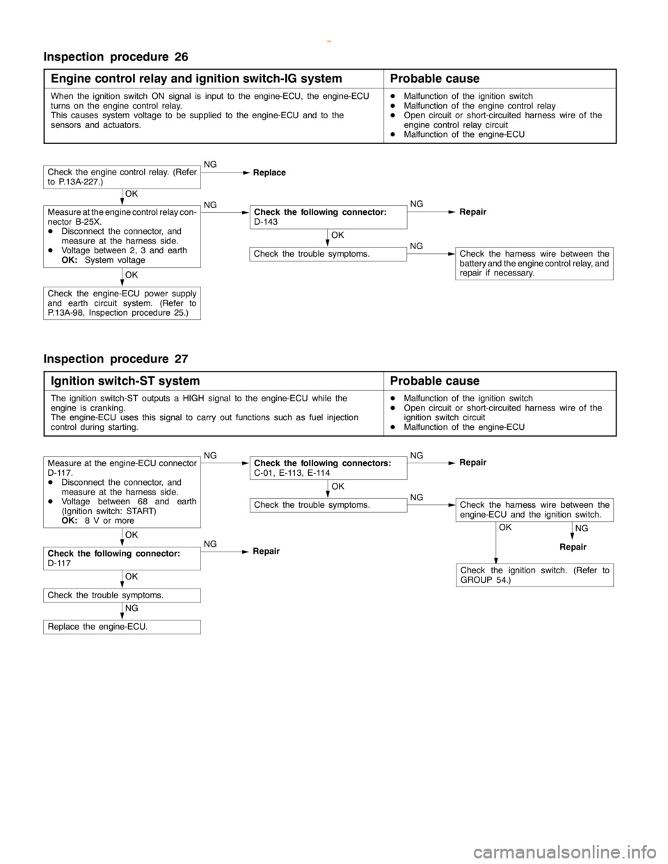
Inspection procedure 26
Engine control relay and ignition switch-IG system
Probable cause
When the ignition switch ON signal is input to the engine-ECU, the engine-ECU
turns on theengine controlrelay.
This causes system voltage to be supplied to the engine-ECU and to the
sensors and actuators.DMalfunction of the ignition switch
DMalfunction of the engine controlrelay
DOpen circuit or short-circuited harness wire of the
engine controlrelay circuit
DMalfunction of the engine-ECU
OK
Check the trouble symptoms.NGCheck the harness wire between the
battery and theengine controlrelay, and
repair if necessary.
OK
Check the engine-ECU power supply
and earth circuit system. (Refer to
P.13A-98, Inspection procedure 25.)
OK
Measure at the engine controlrelay con-
nector B-25X.
DDisconnect the connector, and
measure at the harness side.
DVoltage between 2, 3 and earth
OK:
System voltageNGCheck the following connector:
D-143NG
Repair
Check theengine controlrelay. (Refer
to P.13A-227.)NG
Replace
Inspection procedure 27
Ignition switch-ST system
Probable cause
The ignition switch-ST outputs a HIGH signal to the engine-ECU while the
engine iscranking.
The engine-ECU uses this signal to carry out functions such as fuel injection
control during starting.DMalfunction of the ignition switch
DOpen circuit or short-circuited harness wire of the
ignition switch circuit
DMalfunction of the engine-ECU
NG
RepairOK
Check the ignition switch. (Refer to
GROUP 54.)
NG
Replace the engine-ECU.
OK
Check the trouble symptoms.
OK
Check the following connector:
D-117NG
RepairOK
Check the trouble symptoms.NGCheck the harness wire between the
engine-ECU and the ignition switch.
Measure at the engine-ECU connector
D-117.
DDisconnect the connector, and
measure at the harness side.
DVoltage between 68 and earth
(Ignition switch: START)
OK:
8 V or moreNGCheck the following connectors:
C-01, E-113, E-114NG
Repair
www.WorkshopManuals.co.uk
Purchased from www.WorkshopManuals.co.uk
Page 315 of 1839
GDI -Troubleshooting
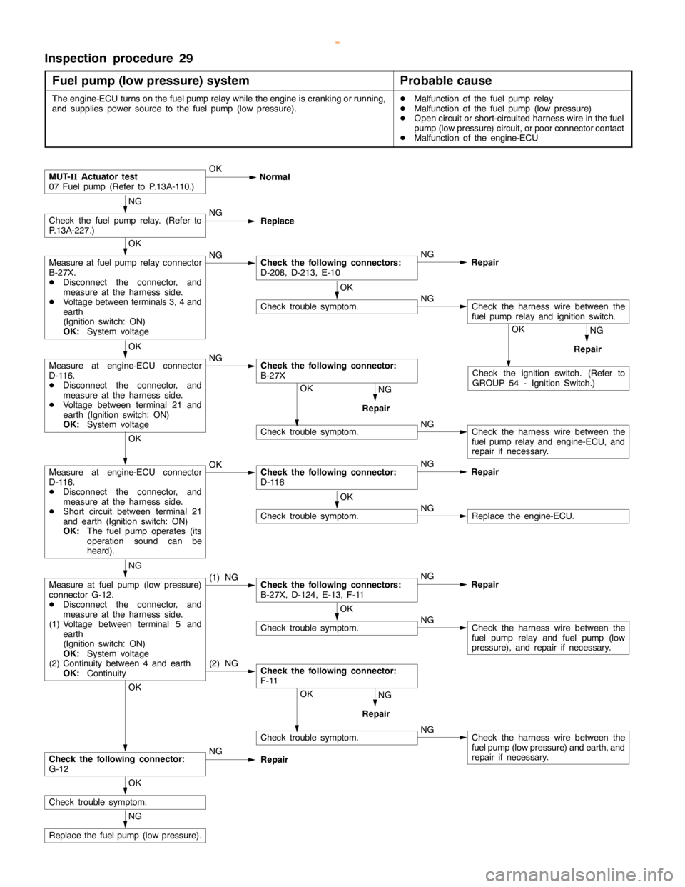
Inspection procedure 29
Fuel pump (low pressure) system
Probable cause
The engine-ECU turns on the fuelpumprelay while theengine iscranking or running,
and supplies power source to the fuelpump(low pressure).DMalfunction of the fuel pumprelay
DMalfunction of the fuel pump(low pressure)
DOpen circuit or short-circuited harness wire in the fuel
pump(low pressure) circuit, or poor connector contact
DMalfunction of the engine-ECU
Check trouble symptom.NGCheck the harness wire between the
fuel pump(low pressure) and earth, and
repair if necessary.
NG
RepairOK
Check trouble symptom.NGCheck the harness wire between the
fuel pumprelay and engine-ECU, and
repair if necessary.
NG
RepairOK
NG
RepairOK
Check the ignition switch. (Refer to
GROUP 54 - Ignition Switch.)
(2) NGCheck the following connector:
F-11
MUT-
IIActuator test
07 Fuel pump(Refer to P.13A-110.)OK
Normal
NG
Check the fuelpumprelay. (Refer to
P.13A-227.)NG
Replace
OK
Measure at fuel pumprelay connector
B-27X.
DDisconnect the connector, and
measure at the harness side.
DVoltage between terminals 3, 4 and
earth
(Ignition switch: ON)
OK:
System voltageNGCheck the following connectors:
D-208, D-213, E-10NG
Repair
OK
Check trouble symptom.NGCheck the harness wire between the
fuel pumprelay and ignition switch.
OK
Measure at engine-ECU connector
D-116.
DDisconnect the connector, and
measure at the harness side.
DVoltage between terminal 21 and
earth (Ignition switch: ON)
OK:
System voltageNGCheck the following connector:
B-27X
OK
Measure at engine-ECU connector
D-116.
DDisconnect the connector, and
measure at the harness side.
DShort circuit between terminal 21
and earth (Ignition switch: ON)
OK:
The fuel pump operates(its
operation sound can be
heard).OKCheck the following connector:
D-116NG
Repair
OK
Check trouble symptom.NGReplace the engine-ECU.
NG
Measure at fuel pump(low pressure)
connector G-12.
DDisconnect the connector, and
measure at the harness side.
(1) Voltage between terminal 5 and
earth
(Ignition switch: ON)
OK:
System voltage
(2) Continuity between 4 and earth
OK:
Continuity(1) NGCheck the following connectors:
B-27X, D-124, E-13, F-11NG
Repair
OK
Check trouble symptom.NGCheck the harness wire between the
fuel pumprelay and fuelpump(low
pressure), and repair if necessary.
OK
Check the following connector:
G-12NG
Repair
OK
Check trouble symptom.
NG
Replace the fuel pump(low pressure).
www.WorkshopManuals.co.uk
Purchased from www.WorkshopManuals.co.uk
Page 322 of 1839

GDI -Troubleshooting
Item
No.Reference
page Inspection
procedure
No. Normal condition Requirements Check items
41Injector drive
time *2DEngine coolant
temperature:
80 - 95_CIdling0.3 - 0.8 ms*1--
80 - 95_C
DLamps, electric
cooling fan and
all accessories:
2,500 r/min0.4 - 1.0 ms
all accessories:
OFF
DTransmission:
Neutral
Sudden racingIncreases
44Ignition
advanceDEngine: After
warm-upIdling5-20_BTDC *1Code No.
P030013A-53
advancewarm-up
DSet a timing
light.
2,500 r/min15 - 35_BTDC
P0300
49A/C relayEngine: After
warm-up, idlingA/C switch: OFFOFF (compressor
clutch is not oper-
ating)Procedure
No.3113A-102
A/C switch: ONON (compressor
clutch is operating)
59Oxygen sen-
sor (rear)DTransmission:
2nd gear
DDrive with
throttle widely
open3,500 r/min600 - 1,000 mVCode No.
P013613A-31
67Stop lamp
switchIgnition switch: ONBrake pedal: De-
pressedOFFProcedure
No.3213A-103
Brake pedal: Re-
leasedON
68EGR valveDEngine coolant
temperature:
80 - 95_C
DLamps, electricIdling2 - 20 STEPCode No.
P040313A-60
cooling fan and
all accessories:
OFF
DTransmission:
Neutral
2,500 r/min0 - 10 STEP
74Fuel pressure
sensorDEngine coolant
temperature:
80 - 95_C
DLamps, electric
cooling fan and
all accessories:
OFF
DTransmission:
NeutralEngine: Idling4 - 6.9 MPaCode No.
P019013A-36
www.WorkshopManuals.co.uk
Purchased from www.WorkshopManuals.co.uk
Page 323 of 1839

GDI -Troubleshooting
Item
No.Reference
page Inspection
procedure
No. Normal condition Requirements Check items
77Accelerator
pedal positionIgnition switch: ONRelease the accel-
erator pedal.985 - 1085 mVCode
No.P122513A-68
sensor (2nd
channel)
Depress the accel-
erator pedal gradu-
ally.Increases in re-
sponse to the ped-
al depression
stroke.
Depress the accel-
erator pedal fully.4,000 mV or more
78Accelerator
pedal positionIgnition switch: ONRelease the accel-
erator pedal.985 - 1085 mVCode
No.P022013A-50
sensor (1st
channel) *3Depress the accel-
erator pedal gradu-
ally.Increases in re-
sponse to pedal
depression stroke.
Depress the accel-
erator pedal fully.4,200 - 4,800 mV
79Throttle posi-
tion sensorDEngine coolant
temperature:Release the accel-
erator pedal.400 - 800 mVCode
No.012013A-25
(1st channel)80 - 95_C
DIgnition switch:
ON (Engine
stopped)
Depress the accel-
erator pedal gradu-
ally.Increases in re-
sponse to pedal
depression stroke.
4,600 - 5,200 mV4,200 - 4,800 mV
Engine: AfterNo load450 - 1,000 mV
warm-up, idling
A/C switch: OFF®
ONIncreases by 100 -
600 mV.
99Fuel injection
modeEngine: After warm
upIdling (after four
minutes or more
have passed since
engine start)Lean compression--
2,500 r/minStoichiometric
metric feedback
Sudden racing after
idle positionOpen loop
www.WorkshopManuals.co.uk
Purchased from www.WorkshopManuals.co.uk