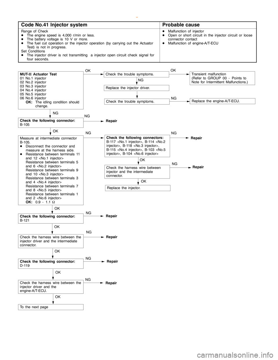
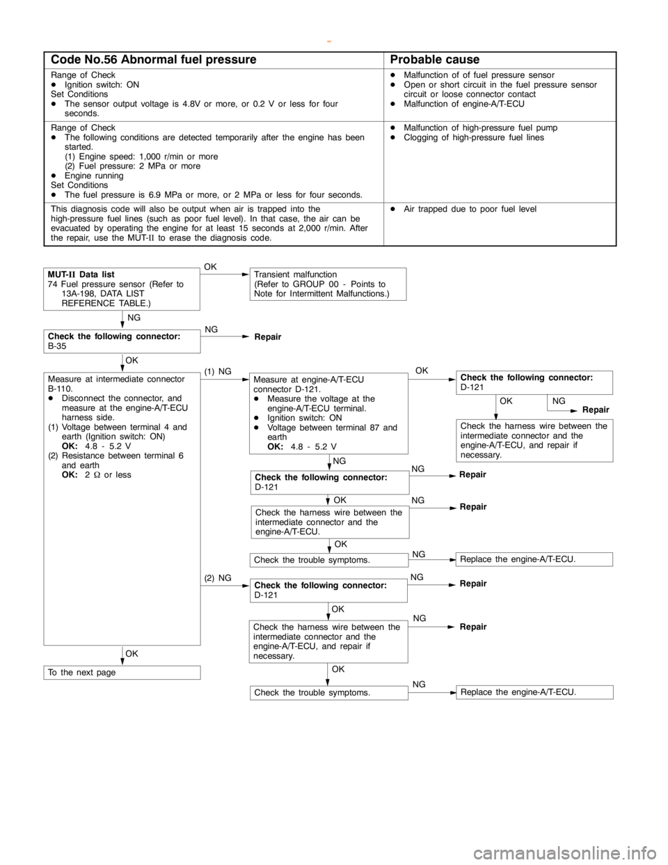
2000 MITSUBISHI MONTERO fuel
[x] Cancel search: fuelPage 324 of 1839

GDI -Troubleshooting
ACTUATOR TEST REFERENCE TABLE
Item
No.Inspection
itemDrive contentsInspection contentsNormal conditionInspection
procedure
No.Reference
page
01InjectorsCut fuel to No. 1
injectorEngine:
After havingIdling condition
becomes differentCode No.
P020113A-38
02Cut fuel to No. 2
injector
warmed up/Engine
is idling
(Cut the fuel supply(becomes unsta-
ble).
Code No.
P020213A-40
03Cut fuel to No. 3
injectorto each injector in
turn and check
cylinders whichCode No.
P020313A-42
04Cut fuel to No. 4
injectordon’t affect idling.)Code No.
P020413A-44
05Cut fuel to No. 5
injectorCode No.
P020513A-46
06Cut fuel to No. 6
injectorCode No.
P020613A-48
07Fuel pump
(low pressure)Fuel pump
operates and
fuel is recirculated.Ignition switch: ONSound of opera-
tion is heard.Procedure
No. 2913A-101
08Purge
control
solenoid valveSolenoid valve
turns from OFF to
ON.Ignition switch: ONSound of opera-
tion can be heard
when solenoid
valve is
driven.Code No.
P044313A-62
17Basic ignition
timingSet the engine-
ECU to ignition
timing adjustment
modeIdling after engine
warm up5_BTDC--
21Condenser fanDrive the fan motorIgnition switch: ONThe fan motor
operatesProcedure
No.2113A-95
34Electronic-
controlled
throttle valve
systemStop the throttle
control servo.Ignition switch: ONThrottle valve is
opened slightly.Code No.
P122013A-64
www.WorkshopManuals.co.uk
Purchased from www.WorkshopManuals.co.uk
Page 326 of 1839

GDI -Troubleshooting
Terminal
No.Normal condition Check requirements (engine condition) Check item
16Purge control solenoid valveDEngine cool-Engine: stoppedSystem voltage
ant tempera-
ture:
80 - 95_C
DIgnition
switch: ON
Engine: Start the
engine, and then
increase engine
speed up to 3,500
r/min.Voltage decreases.
18Condenser fan relayCondenser fan is not operating.System voltage
Condenser fan is operating.0-3V
20Fuel pump relayIgnition switch:Engine: stoppedSystem voltage
ON
Engine: idling0-3V
21A/C relayDEngine: idlingSystem voltage, or changes
DA/C switch: OFF®ON
(Compressor is operating)from momentarily 6 V or
more to 0®3V
31Engine warning lampIgnition switch: OFF®ON0-3V®System voltage
(after several seconds)
41Sensor power supplyIgnition switch: ON4.5 - 5.5 V
42Power supply to accelerator
pedal position sensor (1st
channel)Ignition switch: ON4.5 - 5.5 V
43Crank angle sensorEngine: Cranking0.4 - 4.0 V
Engine: Idling1.5 - 2.5 V
44Engine coolant temperature
sensorIgnition switch:
ONEngine coolant
temperature: 0_C3.2 - 3.5 V
Engine coolant
temperature:
20_C2.3 - 2.9 V
Engine coolant
temperature:
40_C1.5 - 2.1 V
Engine coolant
temperature:
80_C0.4 - 1.0 V
45Engine ignition signalEngine: 3,000 r/min0.3 - 3.0 V
www.WorkshopManuals.co.uk
Purchased from www.WorkshopManuals.co.uk
Page 328 of 1839

GDI -Troubleshooting
Terminal
No.Normal condition Check requirements (engine condition) Check item
63Stop lamp switchDepress the brake pedal.System voltage
Release the brake pedal.0-3V
65A/C switch (2nd channel)Refer to GROUP 55 - Troubleshooting “Check at the A/C-ECU
terminal, engine-ECU output terminals.”
66Clutch switchDepress the clutch pedal.0-3V
Release the clutch pedal.System voltage
68Ignition switch-STEngine: Cranking8V or more
71Oxygen sensor (front)Engine: Warm up, and then hold the
engine speed at 2,500r/min (Use a
digital voltmeter).0«0.8 V alternates.
76Air flow sensor reset signalEngine: Idling0-1V
Engine: 3,000 r/min6-9V
78Throttle position sensor
(2nd channel)Ignition switch:
ONRelease the
accelerator pedal.4.5 - 5.5 V
Depress the
accelerator pedal
fully.0.4 - 0.6 V
79Accelerator pedal position
switchIgnition switch:
ONRelease the
accelerator pedal.0-1V
Depress the
accelerator pedal
fully.4V or more
80Vehicle speed sensorDIgnition switch: ON
DMove the vehicle forward.0«system voltage
alternates.
83A/C switch (1st channel)Engine: IdlingA/C switch: OFF0-3V
A/C switch: ON
(Compressor is
operating)System voltage
88Small lamp switchLighting switch: OFF0-3V
Lighting switch: ON (Taillamp: ON)System voltage
89Oxygen sensor heaterEngine: Idling0-3V
(front)
Engine: 3,500 r/minSystem voltage
90Oxygen sensor heaterEngine: Idling0-3V
(rear)
Engine: 3,500 r/minSystem voltage
92Fuel pressure sensorEngine: Idling0.3 - 4.7 V
www.WorkshopManuals.co.uk
Purchased from www.WorkshopManuals.co.uk
Page 342 of 1839

Page 343 of 1839

Page 344 of 1839

Page 361 of 1839

Page 365 of 1839
