2000 DODGE NEON ESP
[x] Cancel search: ESPPage 386 of 1285
POWER MIRRORS
TABLE OF CONTENTS
page page
GENERAL INFORMATION
INTRODUCTION..........................1
DIAGNOSIS AND TESTING
POWER FOLD AWAY MIRROR SWITCH TEST...1POWER FOLD AWAY MIRROR MOTOR........1
REMOVAL AND INSTALLATION
POWER FOLD-AWAY MIRROR SWITCH.......1
POWER FOLD-AWAY MIRROR...............2
GENERAL INFORMATION
INTRODUCTION
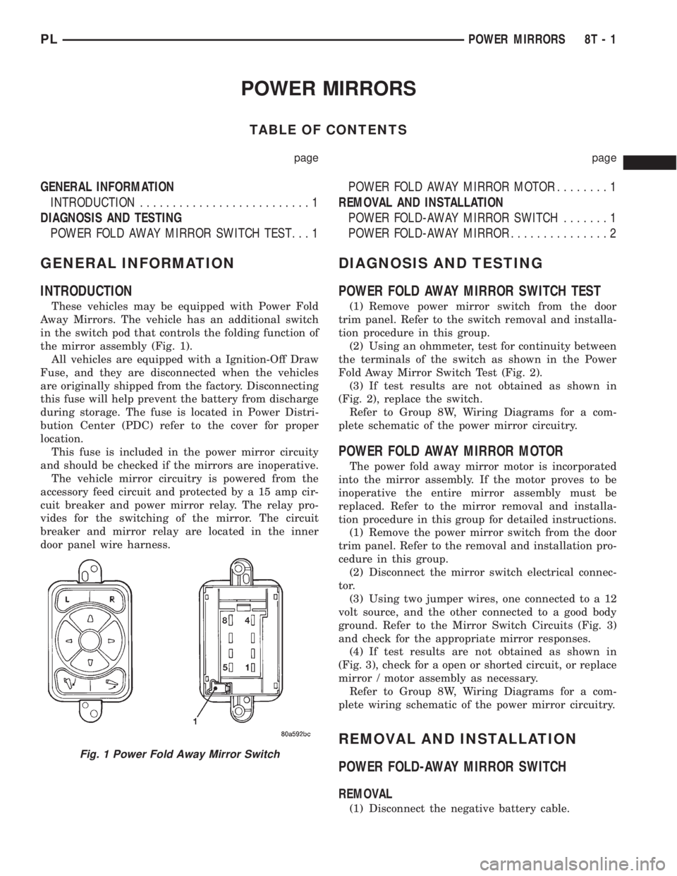
These vehicles may be equipped with Power Fold
Away Mirrors. The vehicle has an additional switch
in the switch pod that controls the folding function of
the mirror assembly (Fig. 1).
All vehicles are equipped with a Ignition-Off Draw
Fuse, and they are disconnected when the vehicles
are originally shipped from the factory. Disconnecting
this fuse will help prevent the battery from discharge
during storage. The fuse is located in Power Distri-
bution Center (PDC) refer to the cover for proper
location.
This fuse is included in the power mirror circuity
and should be checked if the mirrors are inoperative.
The vehicle mirror circuitry is powered from the
accessory feed circuit and protected by a 15 amp cir-
cuit breaker and power mirror relay. The relay pro-
vides for the switching of the mirror. The circuit
breaker and mirror relay are located in the inner
door panel wire harness.
DIAGNOSIS AND TESTING
POWER FOLD AWAY MIRROR SWITCH TEST
(1) Remove power mirror switch from the door
trim panel. Refer to the switch removal and installa-
tion procedure in this group.
(2) Using an ohmmeter, test for continuity between
the terminals of the switch as shown in the Power
Fold Away Mirror Switch Test (Fig. 2).
(3) If test results are not obtained as shown in
(Fig. 2), replace the switch.
Refer to Group 8W, Wiring Diagrams for a com-
plete schematic of the power mirror circuitry.
POWER FOLD AWAY MIRROR MOTOR
The power fold away mirror motor is incorporated
into the mirror assembly. If the motor proves to be
inoperative the entire mirror assembly must be
replaced. Refer to the mirror removal and installa-
tion procedure in this group for detailed instructions.
(1) Remove the power mirror switch from the door
trim panel. Refer to the removal and installation pro-
cedure in this group.
(2) Disconnect the mirror switch electrical connec-
tor.
(3) Using two jumper wires, one connected to a 12
volt source, and the other connected to a good body
ground. Refer to the Mirror Switch Circuits (Fig. 3)
and check for the appropriate mirror responses.
(4) If test results are not obtained as shown in
(Fig. 3), check for a open or shorted circuit, or replace
mirror / motor assembly as necessary.
Refer to Group 8W, Wiring Diagrams for a com-
plete wiring schematic of the power mirror circuitry.
REMOVAL AND INSTALLATION
POWER FOLD-AWAY MIRROR SWITCH
REMOVAL
(1) Disconnect the negative battery cable.
Fig. 1 Power Fold Away Mirror Switch
PLPOWER MIRRORS 8T - 1
Page 400 of 1285
TERMINOLOGY
This a list of terms with there definitions used in
the wiring diagrams.
Built-Up-Export....... Vehicles Built For Sale In
Markets Other Than North America
Except-Built-Up-Export . Vehicles Built For Sale In
North America
LHD ................Left Hand Drive Vehicles
RHD ...............Right Hand Drive Vehicles
ATX . . Automatic Transmission-Front Wheel Drive
MTX ....Manual Transmission-Front Wheel Drive
AT ....Automatic Transmission-Rear Wheel Drive
MT......Manual Transmission-Rear Wheel Drive
SOHC...........Single Over Head Cam Engine
DOHC............Dual Over Head Cam Engine
CONNECTOR INFORMATION
CAUTION: Not all connectors are serviced. Some
connectors are serviced only with a harness. A typ-
ical example might be the Supplemental Restraint
System connectors. Always check parts availability
before attempting a repair.
IDENTIFICATION
In-line connectors are identified by a number, as
follows:
²In-line connectors located on theengine com-
partment harnessareC100series numbers.
²Connectors located on theinstrument panel
harnessareC200series numbers.
²Connectors located on thebody harnessare
C300series numbers.
²Jumper harness connectorsareC400series
numbers.
²Grounds and ground connectorsare identi-
fied with aªGºand follow the same series number-
ing as the in-line connector.
Component connectors are identified by the compo-
nent name instead of a number. Multiple connectors
on a component use a C1, C2, etc. identifier.
LOCATIONS
Section 8W-90 contains connector/ground location
illustrations. The illustrations contain the connector
name (or number)/ground number and component
identification. Connector/ground location charts in
Section 8W-90 reference the illustration number for
components and connectors.
Section 8W-80 shows each connector and the cir-
cuits involved with that connector. The connectors
are identified using the name/number on the Dia-
gram pages.
SPLICE LOCATIONS
Splice Location charts in Section 8W-70 show the
entire splice, and provide references to other sections
the splice serves.
Section 8W-95 contains illustrations that show the
general location of the splices in each harness. The
illustrations show the splice by number, and provide
a written location.
NOTES, CAUTIONS, and WARNINGS
Throughout this group additional important infor-
mation is presented in three ways; Notes, Cautions,
and Warnings.
NOTESare used to help describe how switches or
components operate to complete a particular circuit.
They are also used to indicate different conditions
that may appear on the vehicle. For example, an
up-to and after condition.
CAUTIONSare used to indicate information that
could prevent making an error that may damage the
vehicle.
WARNINGSprovide information to prevent per-
sonal injury and vehicle damage. Below is a list of
general warnings that should be followed any time a
vehicle is being serviced.
WARNING: ALWAYS WEAR SAFETY GLASSES FOR
EYE PROTECTION.
WARNING: USE SAFETY STANDS ANYTIME A PRO-
CEDURE REQUIRES BEING UNDER A VEHICLE.
WARNING: BE SURE THAT THE IGNITION SWITCH
ALWAYS IS IN THE OFF POSITION, UNLESS THE
PROCEDURE REQUIRES IT TO BE ON.
WARNING: SET THE PARKING BRAKE WHEN
WORKING ON ANY VEHICLE. AN AUTOMATIC
TRANSMISSION SHOULD BE IN PARK. A MANUAL
TRANSMISSION SHOULD BE IN NEUTRAL.
WARNING: OPERATE THE ENGINE ONLY IN A
WELL-VENTILATED AREA.
WARNING: KEEP AWAY FROM MOVING PARTS
WHEN THE ENGINE IS RUNNING, ESPECIALLY THE
FAN AND BELTS.
WARNING: TO PREVENT SERIOUS BURNS, AVOID
CONTACT WITH HOT PARTS SUCH AS THE RADIA-
TOR, EXHAUST MANIFOLD(S), TAIL PIPE, CATA-
LYTIC CONVERTER, AND MUFFLER.
PL8W - 01 GENERAL INFORMATION 8W - 01 - 7
DESCRIPTION AND OPERATION (Continued)
Page 491 of 1285
POWER
DISTRIBUTION
CENTER
530A
FUSE
5
9
CONTROLLER
ANTI-LOCK
BRAKE
BATT A0
10
2315A
FUSE
23
824
Z1
12
BK BK12Z1
Z1
12
BK
G103 S119
6
5
L50
20
WT/TN
18
L50
18
WT/TN
S108
F32
18
PK/DB
BRAKE
LAMP
SWITCH
OUTPUT
GROUND GROUND FUSED
B(+) B(+)FUSED
25
RD/DG12 A10 840A
FUSE
8
BRAKE
LAMP
SWITCH
PCI
BUS
A20
12
RD/DB
2
D25
18
VT/YL
D25
20
VT/YL
S104
CONNECTORLINK DATA
(8W-10-2)
(8W-10-3)
(8W-10-11)(8W-10-7)
(8W-10-18)
(8W-15-7) (8W-15-5) (8W-10-18) (8W-10-11)
(8W-30-13)
(8W-30-4)
(8W-30-4)
8W - 35 - 2 8W-35 ANTI-LOCK BRAKESPL
008W-10PLI03502
Page 493 of 1285
SENSOR SPEED
WHEEL
FRONT
LEFT
LEFT
REAR
WHEEL
SPEED
SENSORRIGHT
FRONT
WHEEL
SPEED
SENSOR
RIGHT
REAR
WHEEL
SPEED
SENSOR
LEFT
FRONT
WHEEL
SPEED
SENSOR
(-)12-VOLT
SUPPLY
(-) SENSORSPEED WHEELREARLEFT RIGHT
FRONT
WHEEL
SPEED
SENSOR
(-) (-)SENSORSPEED WHEELREAR RIGHT
125619202322 B8
18
RD/DB
B9
18
RDB6
18
WT/DBB7
18
WT
B2
20
YL B1
20
YL/DB B3
20
LG/DBB4
20
LG
12
12
12
12
CONTROLLER
ANTI-LOCK
BRAKE
PAIR TWISTED
TWISTED
PAIR
TWISTED
PAIR
PAIR TWISTED
2C10613C1064
B3
18
LG/DBB4
18
LGB1
18
YL/DBB2
18
YL
TWISTED
PAIR
PAIR TWISTED
12-VOLT
SUPPLY12-VOLT
SUPPLY SUPPLY12-VOLT
8W - 35 - 4 8W-35 ANTI-LOCK BRAKESPL
008W-10PLI03504
Page 725 of 1285
MOPARtGASKET SEALANT
MopartGasket Sealant is a slow drying, perma-
nently soft sealer. This material is recommended for
sealing threaded fittings and gaskets against leakage
of oil and coolant. Can be used on threaded and
machined parts under all temperatures. This mate-
rial is used on engines with multi-layer steel (MLS)
cylinder head gaskets. This material also will pre-
vent corrosion. MopartGasket Sealant is available in
a 13 oz. aerosol can or 4 oz./16 oz. can w/applicator.
FORM-IN-PLACE GASKET AND SEALER
APPLICATION
Assembling parts using a form-in-place gasket
requires care but it's easier then using precut gas-
kets.
MopartGasket Maker material should be applied
sparingly 1 mm (0.040 in.) diameter or less of sealant
to one gasket surface. Be certain the material sur-
rounds each mounting hole. Excess material can eas-
ily be wiped off. Components should be torqued in
place within 15 minutes. The use of a locating dowel
is recommended during assembly to prevent smear-
ing material off the location.
MopartEngine RTV GEN II or ATF RTV gasket
material should be applied in a continuous bead
approximately 3 mm (0.120 in.) in diameter. All
mounting holes must be circled. For corner sealing, a
3.17 or 6.35 mm (1/8 or 1/4 in.) drop is placed in the
center of the gasket contact area. Uncured sealant
may be removed with a shop towel. Components
should be torqued in place while the sealant is still
wet to the touch (within 10 minutes). The usage of a
locating dowel is recommended during assembly to
prevent smearing material off the location.
MopartGasket Sealant in an aerosol can should be
applied using a thin, even coat sprayed completely
over both surfaces to be joined, and both sides of a
gasket. Then proceed with assembly. Material in a
can w/applicator can be brushed on evenly over the
sealing surfaces. Material in an aerosol can should be
used on engines with multi-layer steel gaskets.
ENGINE GASKET SURFACE PREPARATION
To ensure engine gasket sealing, proper surface
preparation must be performed, especially with the
use of aluminum engine components and multi-layer
steel cylinder head gaskets.
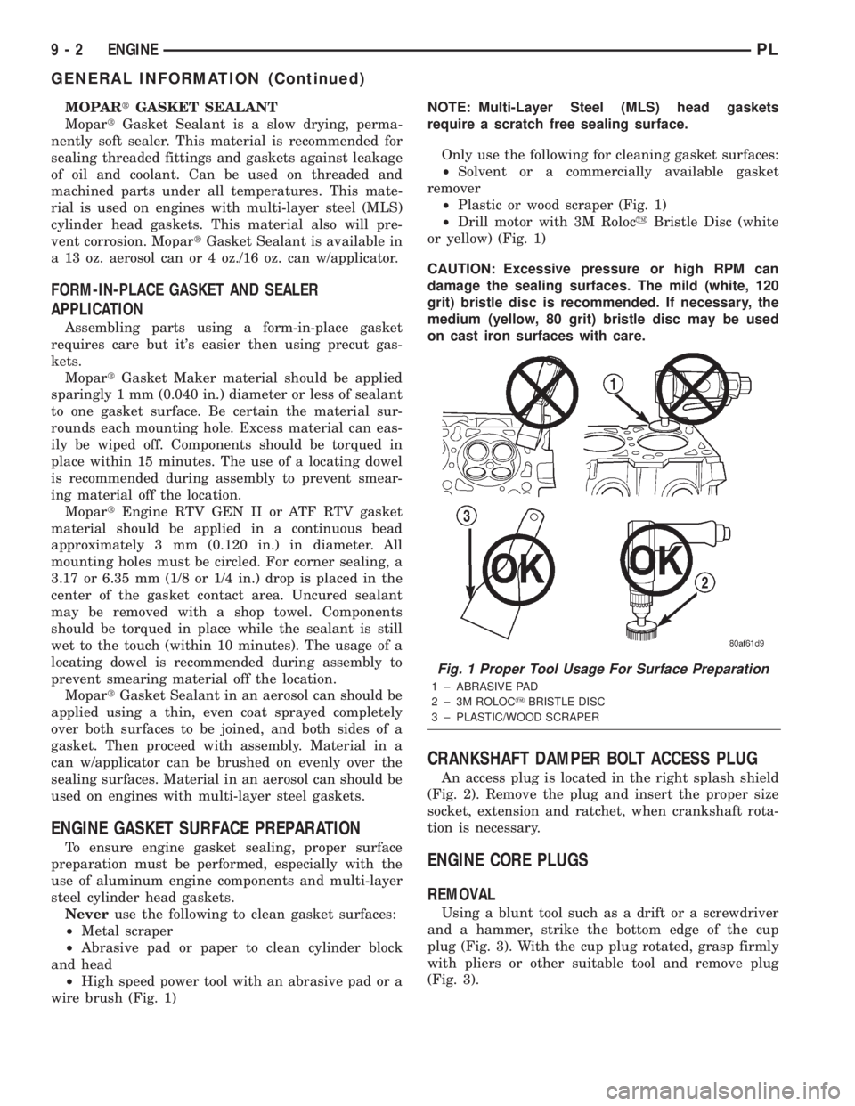
Neveruse the following to clean gasket surfaces:
²Metal scraper
²Abrasive pad or paper to clean cylinder block
and head
²High speed power tool with an abrasive pad or a
wire brush (Fig. 1)NOTE: Multi-Layer Steel (MLS) head gaskets
require a scratch free sealing surface.
Only use the following for cleaning gasket surfaces:
²Solvent or a commercially available gasket
remover
²Plastic or wood scraper (Fig. 1)
²Drill motor with 3M RolocyBristle Disc (white
or yellow) (Fig. 1)
CAUTION: Excessive pressure or high RPM can
damage the sealing surfaces. The mild (white, 120
grit) bristle disc is recommended. If necessary, the
medium (yellow, 80 grit) bristle disc may be used
on cast iron surfaces with care.
CRANKSHAFT DAMPER BOLT ACCESS PLUG
An access plug is located in the right splash shield
(Fig. 2). Remove the plug and insert the proper size
socket, extension and ratchet, when crankshaft rota-
tion is necessary.
ENGINE CORE PLUGS
REMOVAL
Using a blunt tool such as a drift or a screwdriver
and a hammer, strike the bottom edge of the cup
plug (Fig. 3). With the cup plug rotated, grasp firmly
with pliers or other suitable tool and remove plug
(Fig. 3).
Fig. 1 Proper Tool Usage For Surface Preparation
1 ± ABRASIVE PAD
2 ± 3M ROLOCYBRISTLE DISC
3 ± PLASTIC/WOOD SCRAPER
9 - 2 ENGINEPL
GENERAL INFORMATION (Continued)
Page 733 of 1285
make sure the dye is thoroughly mixed as indicated
with a bright yellow color under a black light.
(3) Using a black light, inspect the entire engine
for fluorescent dye, particularly at the suspected area
of oil leak. If the oil leak is found and identified,
repair per service manual instructions.
(4) If dye is not observed, drive the vehicle at var-
ious speeds for approximately 24 km (15 miles), and
repeat inspection.
(5)If the oil leak source is not positively
identified at this time, proceed with the air leak
detection test method as follows:
²Disconnect the fresh air hose (makeup air) at
the cylinder head cover and plug or cap the nipple on
the cover.
²Remove the PCV valve hose from the cylinder
head cover. Cap or plug the PCV valve nipple on the
cover.
²Attach an air hose with pressure gauge and reg-
ulator to the dipstick tube.
CAUTION: Do not subject the engine assembly to
more than 20.6 kpa (3 PSI) of test pressure.
²Gradually apply air pressure from 1 psi to 2.5
psi maximum while applying soapy water at the sus-
pected source. Adjust the regulator to the suitable
test pressure that provides the best bubbles which
will pinpoint the leak source. If the oil leak is
detected and identified, repair per service manual
procedures.
²If the leakage occurs at the crankshaft rear oil
seal area, refer to the section, Inspection for Rear
Seal Area Leak.
(6) If no leaks are detected, turn off the air supply.
Remove the air hose, all plugs, and caps. Install the
PCV valve and CCV hose. Proceed to next step.
(7) Clean the oil off the suspect oil leak area using
a suitable solvent. Drive the vehicle at various
speeds approximately 24 km (15 miles). Inspect the
engine for signs of an oil leak by using a black light.
INSPECTION FOR REAR SEAL AREA LEAKS
Since it is sometimes difficult to determine the
source of an oil leak in the rear seal area of theengine, a more involved inspection is necessary. The
following steps should be followed to help pinpoint
the source of the leak.
If the leakage occurs at the crankshaft rear oil seal
area:
(1) Disconnect the battery.
(2) Raise the vehicle.
(3) Remove torque converter or clutch housing
cover and inspect rear of block for evidence of oil.
Use a black light to check for the oil leak. If a leak is
present in this area remove transmission for further
inspection.
(a) Circular spray pattern generally indicates
seal leakage or crankshaft damage.
(b) Where leakage tends to run straight down,
possible causes are a porous block, oil galley cup
plug, bedplate to cylinder block mating surfaces
and seal bore. See proper repair procedures for
these items.
(4) If no leaks are detected, pressurized the crank-
case as previously described.
CAUTION: Do not exceed 20.6 kPa (3 psi).
(5) If the leak is not detected, very slowly turn the
crankshaft and watch for leakage. If a leak is
detected between the crankshaft and seal while
slowly turning the crankshaft, it is possible the
crankshaft seal surface is damaged. The seal area on
the crankshaft could have minor nicks or scratches
that can be polished out with emery cloth.
CAUTION: Use extreme caution when crankshaft
polishing is necessary to remove minor nicks and
scratches. The crankshaft seal flange is especially
machined to complement the function of the rear oil
seal.
(6) For bubbles that remain steady with shaft
rotation, no further inspection can be done until dis-
assembled.
(7) After the oil leak root cause and appropriate
corrective action have been identified, refer to Crank-
shaft Oil SealÐRear for proper replacement proce-
dures.
9 - 10 ENGINEPL
DIAGNOSIS AND TESTING (Continued)
Page 741 of 1285
der head. The rocker shafts route oil to the rocker
arms/hydraulic lash adjuster assemblies.
SPLASH LUBRICATION
Oil returning to the pan from pressurized compo-
nents supplies lubrication to the valve stems. Cylin-
der bores and wrist pins are splash lubricated from
directed slots on the connecting rod thrust collars.
DIAGNOSIS AND TESTING
CHECKING ENGINE OIL PRESSURE
(1) Remove oil pressure switch and install gauge
assembly C-3292 with adaptor.
(2) Run engine until thermostat opens.
CAUTION: If oil pressure is 0 at idle, Do Not per-
form the 3000 RPM test in the next step.
(3) Oil Pressure:Curb Idle25 kPa (4 psi) mini-
mum3000 RPM170-550 kPa (25-80 psi).
(4) If oil pressure is 0 at idle. Shut off engine,
check for pressure relief valve stuck open, a clogged
oil pick-up screen or a damaged oil pick-up tube
O-ring.
SERVICE PROCEDURES
CYLINDER BORE AND PISTON SIZING
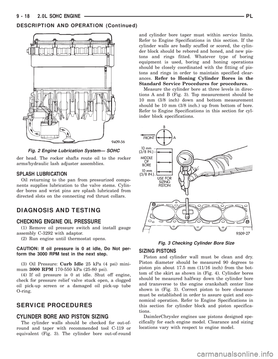
The cylinder walls should be checked for out-of-
round and taper with recommended tool C-119 or
equivalent (Fig. 3). The cylinder bore out-of-roundand cylinder bore taper must within service limits.
Refer to Engine Specifications in this section. If the
cylinder walls are badly scuffed or scored, the cylin-
der block should be rebored and honed, and new pis-
tons and rings fitted. Whatever type of boring
equipment is used, boring and honing operations
should be closely coordinated with the fitting of pis-
tons and rings in order to maintain specified clear-
ances.Refer to Honing Cylinder Bores in the
Standard Service Procedures for procedures.
Measure the cylinder bore at three levels in direc-
tions A and B (Fig. 3). Top measurement should be
10 mm (3/8 inch) down and bottom measurement
should be 10 mm (3/8 inch.) up from bottom of bore.
Refer to Engine Specifications in this section for cyl-
inder block specifications.
SIZING PISTONS
Piston and cylinder wall must be clean and dry.
Piston diameter should be measured 90 degrees to
piston pin about 17.5 mm (11/16 inch) from the bot-
tom of the skirt as shown in (Fig. 4). Cylinder bores
should be measured halfway down the cylinder bore
and transverse to the engine crankshaft center line
shown in (Fig. 3). Correct piston to bore clearance
must be established in order to assure quiet and eco-
nomical operation. Refer to Engine Specifications in
this section for cylinder block and piston specifica-
tions.
DaimlerChrysler engines use pistons designed spe-
cifically for each engine model. Clearance and sizing
locations vary with respect to engine model.
Fig. 2 Engine Lubrication SystemÐ SOHC
Fig. 3 Checking Cylinder Bore Size
9 - 18 2.0L SOHC ENGINEPL
DESCRIPTION AND OPERATION (Continued)
Page 757 of 1285
INSPECT CYLINDER HEAD FOR THE FOLLOWING:
NOTE:
²Check oil feed holes for blockage.
²Inspect cylinder head camshaft bearings for
wear, Refer to Cylinder Head, Inspection and Clean-
ing.
²Check camshaft bearing journals for scratches
and worn areas. If light scratches are present, they
may be removed with 400 grit sand paper. If deep
scratches are present, replace the camshaft and
check the cylinder head for damage. Replace the
cylinder head if worn or damaged. Check the lobes
for pitting and wear. If the lobes show signs of
wear, check the corresponding rocker arm roller for
wear or damage. Replace rocker arm/hydraulic lash
adjuster if worn or damaged. If lobes show signs of
pitting on the nose, flank or base circle; replace the
camshaft.
INSTALLATION
(1) Lubricate the camshaft journals with oil and
install camshaftwithoutrocker arm assemblies
installed.
(2) Install camshaft target magnet into the end of
the camshaft. Tighten mounting screw to 3.4 N´m (30
in. lbs.).
(3) Install camshaft position sensor and tighten
mounting screws to 9 N´m (80 in. lbs.).
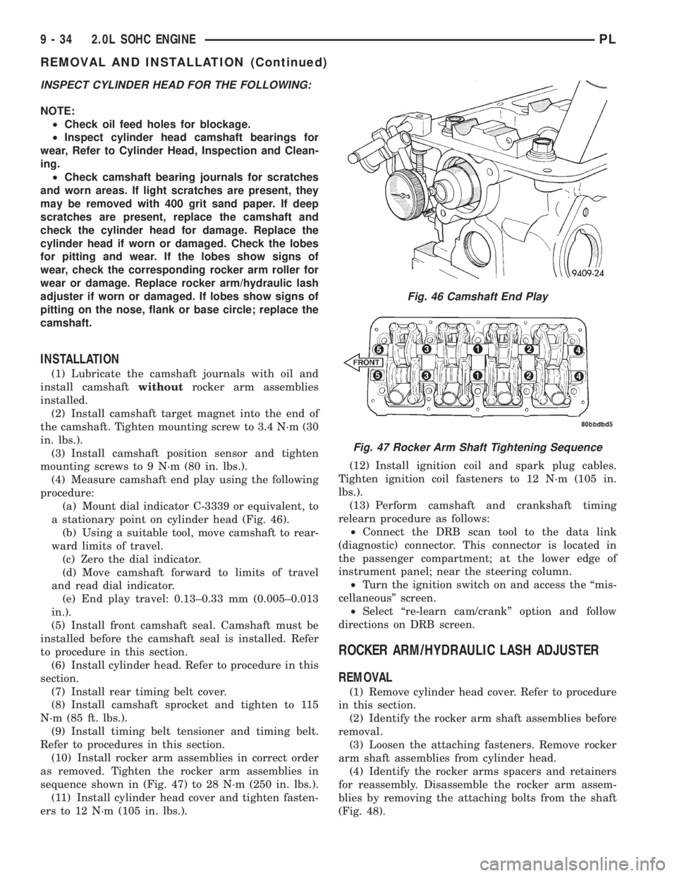
(4) Measure camshaft end play using the following
procedure:
(a) Mount dial indicator C-3339 or equivalent, to
a stationary point on cylinder head (Fig. 46).
(b) Using a suitable tool, move camshaft to rear-
ward limits of travel.
(c) Zero the dial indicator.
(d) Move camshaft forward to limits of travel
and read dial indicator.
(e) End play travel: 0.13±0.33 mm (0.005±0.013
in.).
(5) Install front camshaft seal. Camshaft must be
installed before the camshaft seal is installed. Refer
to procedure in this section.
(6) Install cylinder head. Refer to procedure in this
section.
(7) Install rear timing belt cover.
(8) Install camshaft sprocket and tighten to 115
N´m (85 ft. lbs.).
(9) Install timing belt tensioner and timing belt.
Refer to procedures in this section.
(10) Install rocker arm assemblies in correct order
as removed. Tighten the rocker arm assemblies in
sequence shown in (Fig. 47) to 28 N´m (250 in. lbs.).
(11) Install cylinder head cover and tighten fasten-
ers to 12 N´m (105 in. lbs.).(12) Install ignition coil and spark plug cables.
Tighten ignition coil fasteners to 12 N´m (105 in.
lbs.).
(13) Perform camshaft and crankshaft timing
relearn procedure as follows:
²Connect the DRB scan tool to the data link
(diagnostic) connector. This connector is located in
the passenger compartment; at the lower edge of
instrument panel; near the steering column.
²Turn the ignition switch on and access the ªmis-
cellaneousº screen.
²Select ªre-learn cam/crankº option and follow
directions on DRB screen.
ROCKER ARM/HYDRAULIC LASH ADJUSTER
REMOVAL
(1) Remove cylinder head cover. Refer to procedure
in this section.
(2) Identify the rocker arm shaft assemblies before
removal.
(3) Loosen the attaching fasteners. Remove rocker
arm shaft assemblies from cylinder head.
(4) Identify the rocker arms spacers and retainers
for reassembly. Disassemble the rocker arm assem-
blies by removing the attaching bolts from the shaft
(Fig. 48).
Fig. 46 Camshaft End Play
Fig. 47 Rocker Arm Shaft Tightening Sequence
9 - 34 2.0L SOHC ENGINEPL
REMOVAL AND INSTALLATION (Continued)