2000 DODGE NEON ESP
[x] Cancel search: ESPPage 1104 of 1285
The PCM is programmed to maintain the optimum
air/fuel ratio of 14.7 to 1. This is done by making
short term corrections in the fuel injector pulse width
based on the O2S output. The programmed memory
acts as a self calibration tool that the engine control-
ler uses to compensate for variations in engine spec-
ifications, sensor tolerances and engine fatigue over
the life span of the engine. By monitoring the actual
air-fuel ratio with the O2S (short term) and multiply-
ing that with the program long-term (adaptive) mem-
ory and comparing that to the limit, it can be
determined whether it will pass an emissions test. If
a malfunction occurs such that the PCM cannot
maintain the optimum A/F ratio, then the MIL will
be illuminated.
Monitor OperationÐFuel systems monitors do
not have a pre-test because they are continuously
running monitors. Therefore, the PCM constantly
monitors Short Term Compensation and Long Term
Adaptive memory.
Lean: If at anytime during a lean engine operation,
short term compensation multiplied by long term
adaptive exceeds a certain percentage for an
extended period, the PCM sets a Fuel System Lean
Fault for that trip and a Freeze Frame is entered.
Rich: If at anytime during a rich operation, Short
Term Compensation multiplied by Long Term Adap-
tive is less than a predetermined value, the PCM
checks the Purge Free Cells.
Purge Free Cells are values placed in Adaptive
Memory cells when the EVAP Purge Solenoid is OFF.
Two, three or four Purge Free cells are used. One cor-
responds to an Adaptive Memory cell at idle, the
other to a cell that is off-idle. For example, if a Purge
Free cell is labeled PFC1, it would hold the value for
Adaptive Memory cell C1 under non-purge condi-
tions.
If all Purge Free Cells are less than a certain per-
centage, and the Adaptive Memory factor is less than
a certain percentage, the PCM sets a Fuel System
Rich fault for that trip and a Freeze Frame is
entered.
The Fuel Monitor is a two trip monitor. The PCM
records engine data in Freeze Frame upon setting of
the first fault, or maturing code. When the fuel mon-
itor fails on a second consecutive trip, the code is
matured and the MIL is illuminated. The stored
Freeze Frame data is still from the first fault.
In order for the PCM to extinguish the MIL, the
Fuel Monitor must pass in a Similar Condition Win-
dow. The similar conditions relate to RPM and load.
The engine must be within a predetermined percent-
age of both RPM and load when the monitor runs to
count a good trip. As with all DTCs, three good tripsare required to extinguish the MIL and 40 warm up
cycles are required to erase the DTC. If the engine
does not run in a Similar Conditions Window, the
Task Manager extinguishes the MIL after 80 good
trips.
Enabling ConditionsÐThe following conditions
must be met to operate the fuel control monitor:
²PCM not in fuel crank mode (engine running)
²PCM in Closed Loop fuel control
²Fuel system updating Long Term Adaptive
²Fuel level above 15% of capacity
²Fuel level below 85% of capacity
Pending ConditionsÐThe Fuel Control Monitor
does not operate if the MIL is illuminated for any of
the following:
²Misfire Monitor
²Upstream O2S
²EVAP Purge Solenoid Electrical PCM Self Test
Fault
²Camshaft or Crankshaft Position Sensor
²Fuel Injectors
²Ignition Coil Primary
²Throttle Position (TPS) Sensor
²Engine Coolant Temperature (ECT) Sensor
²Manifold Absolute Pressure (MAP) Sensor
²Idle Air Control (IAC)
²5V Output Too Low
²EGR Monitor
²EGR Solenoid Circuit
²Vehicle Speed Sensor
²Oxygen Sensor Monitor
²Oxygen Sensor Heater Monitor
²Oxygen Sensor Electrical
²Idle Speed Rationality
²Intake Air Temperature
SuspendÐThe Task Manager will suspend
maturing a Fuel System fault if any of the following
are present:
²Oxygen Sensor Response, Priority 1
²O2 Heater, Priority 1
²Misfire Monitor, Priority 2
EVAPORATIVE EMISSIONS MONITOR
LEAK DETECTION PUMP MONITORÐThe
leak detection assembly incorporates two primary
functions: it must detect a leak in the evaporative
system and seal the evaporative system so the leak
detection test can be run.
The primary components within the assembly are:
A three port solenoid that activates both of the func-
tions listed above; a pump which contains a switch,
two check valves and a spring/diaphragm, a canister
vent valve (CVV) seal which contains a spring loaded
vent seal valve.
PLEMISSION CONTROL SYSTEMS 25 - 17
DESCRIPTION AND OPERATION (Continued)
Page 1105 of 1285
Immediately after a cold start, between predeter-
mined temperature thresholds limits, the three port
solenoid is briefly energized. This initializes the
pump by drawing air into the pump cavity and also
closes the vent seal. During non test conditions the
vent seal is held open by the pump diaphragm
assembly which pushes it open at the full travel posi-
tion. The vent seal will remain closed while the
pump is cycling due to the reed switch triggering of
the three port solenoid that prevents the diaphragm
assembly from reaching full travel. After the brief
initialization period, the solenoid is de-energized
allowing atmospheric pressure to enter the pump
cavity, thus permitting the spring to drive the dia-
phragm which forces air out of the pump cavity and
into the vent system. When the solenoid is energized
and de energized, the cycle is repeated creating flow
in typical diaphragm pump fashion. The pump is con-
trolled in 2 modes:
Pump Mode:The pump is cycled at a fixed rate to
achieve a rapid pressure build in order to shorten the
overall test length.
Test Mode:The solenoid is energized with a fixed
duration pulse. Subsequent fixed pulses occur when
the diaphragm reaches the Switch closure point.
The spring in the pump is set so that the system
will achieve an equalized pressure of about 7.5º H20.
The cycle rate of pump strokes is quite rapid as the
system begins to pump up to this pressure. As the
pressure increases, the cycle rate starts to drop off. If
there is no leak in the system, the pump would even-
tually stop pumping at the equalized pressure. If
there is a leak, it will continue to pump at a rate rep-
resentative of the flow characteristic of the size of the
leak. From this information we can determine if the
leak is larger than the required detection limit (cur-
rently set at.040º orifice by CARB). If a leak is
revealed during the leak test portion of the test, the
test is terminated at the end of the test mode and no
further system checks will be performed.
After passing the leak detection phase of the test,
system pressure is maintained by turning on the
LDP's solenoid until the purge system is activated.
Purge activation in effect creates a leak. The cycle
rate is again interrogated and when it increases due
to the flow through the purge system, the leak check
portion of the diagnostic is complete.
The canister vent valve will unseal the system
after completion of the test sequence as the pump
diaphragm assembly moves to the full travel position.
Evaporative system functionality will be verified by
using the stricter evap purge flow monitor. At an
appropriate warm idle the LDP will be energized to
seal the canister vent. The purge flow will be clocked
up from some small value in an attempt to see a
shift in the 02 control system. If fuel vapor, indicatedby a shift in the 02 control, is present the test is
passed. If not, it is assumed that the purge system is
not functioning in some respect. The LDP is again
turned off and the test is ended.
Enabling Conditions for Systems with LDP
²Ambient Air Temperature
²Barometric Pressure
²Fuel level
²Engine Temperature
²No stalling
²Battery voltage
NON-LDP VEHICLESÐOn a vehicle without an
EVAP leak detection pump system, changes in short
term memory and movement in target IAC at idle or
idle speed change, are used to monitor the system.
There are two stages for this test.
Stage OneÐStage one is a non-intrusive test.
The PCM compares adaptive memory values between
purge and purge-free cells. The PCM uses these val-
ues to determine the amount of fuel vapors entering
the system. If the difference between the cells
exceeds a predetermined value, the test passes. If
not, then the monitor advances to state two.
Stage TwoÐOnce the enabling conditions are
met, the PCM de-energizes the Duty Cycle Purge
(DCP) solenoid. The PCM then waits until engine
RPM, Short Term Compensation and Idle Air Control
have all stabilized. Once stable, the PCM increments
the DCP solenoid cycle rate approximately 6% every
8 engine revolutions. If during the test any one of
three conditions occur before the DCP cycle reaches
100%, the EVAP system is considered to be opera-
tional and the test passes. These conditions are as
follows:
²RPM rises by a predetermined amount
²Short Term drops by a predetermined amount
²Idle Air Control closes by a predetermined
amount
When none of the previous conditions occur, the
test fails and the PCM increments a counter by one.
When the PCM runs the test three times during a
trip, and the counter has been incremented to three,
the monitor fails and a Freeze Frame is stored.
Enabling Conditions (Stage Two)ÐThe follow-
ing conditions must be met to enable the EVAP Mon-
itor (without LDP)
²Ambient Air Temperature
²Barometric Pressure
²Fuel level
²Engine Temperature
²Engine run time
²RPM stable
²MAP
²Generator, radiator fans, A/C clutch
Pending Conditions-With or Without LDPÐ
The EVAP Monitor is suspended and does not run,
25 - 18 EMISSION CONTROL SYSTEMSPL
DESCRIPTION AND OPERATION (Continued)
Page 1107 of 1285
NOTE: Comprehensive component monitors are
continuous. Therefore, enabling conditions do not
apply.
Input RationalityÐWhile input signals to the
PCM are constantly being monitored for electrical
opens and shorts, they are also tested for rationality.
This means that the input signal is compared against
other inputs and information to see if it makes sense
under the current conditions.
PCM sensor inputs that are checked for rationality
include:
²Manifold Absolute Pressure (MAP) Sensor
²Oxygen Sensor (O2S)
²Engine Coolant Temperature (ECT) Sensor
²Camshaft Position (CMP) Sensor
²Vehicle Speed Sensor
²Crankshaft Position (CKP) Sensor
²Intake Air Temperature (IAT) Sensor
²Throttle Position (TPS) Sensor
²Ambient/Battery Temperature Sensors
²Power Steering Switch
²Oxygen Sensor Heater
²Engine Controller
²Brake Switch
²Leak Detection Pump Switch
²P/N Switch
²Trans Controls
Output FunctionalityÐPCM outputs are tested
for functionality in addition to testing for opens and
shorts. When the PCM provides a voltage to an out-
put component, it can verify that the command was
carried out by monitoring specific input signals for
expected changes. For example, when the PCM com-
mands the Idle Air Control (IAC) Motor to a specific
position under certain operating conditions, it expects
to see a specific (target) idle speed (RPM). If it does
not, it stores a DTC.
PCM outputs monitored for functionality include:
²Fuel Injectors
²Ignition Coils
²Torque Converter Clutch Solenoid
²Idle Air Control
²Purge Solenoid
²EGR Solenoid
²LDP Solenoid
²Radiator Fan Control
²Trans Controls
OXYGEN SENSOR (O2S) MONITOR
DESCRIPTIONÐEffective control of exhaust
emissions is achieved by an oxygen feedback system.
The most important element of the feedback system
is the O2S. The O2S is located in the exhaust path.
Once it reaches operating temperature 300É to 350ÉC
(572É to 662ÉF), the sensor generates a voltage that
is inversely proportional to the amount of oxygen inthe exhaust. When there is a large amount of oxygen
in the exhaust caused by a lean condition, the sensor
produces a low voltage, below 450 mV. When the oxy-
gen content is lower, caused by a rich condition, the
sensor produces a higher voltage, above 450mV.
The information obtained by the sensor is used to
calculate the fuel injector pulse width. This main-
tains a 14.7 to 1 air fuel (A/F) ratio. At this mixture
ratio, the catalyst works best to remove hydrocarbons
(HC), carbon monoxide (CO) and nitrous oxide (NOx)
from the exhaust.
The O2S is also the main sensing element for the
EGR, Catalyst and Fuel Monitors.
The O2S may fail in any or all of the following
manners:
²Slow response rate (Big Slope)
²Reduced output voltage (Half Cycle)
²Heater Performance
Slow Response Rate (Big Slope)ÐResponse
rate is the time required for the sensor to switch
from lean to rich signal output once it is exposed to a
richer than optimum A/F mixture or vice versa. As
the PCM adjusts the air/fuel ratio, the sensor must
be able to rapidly detect the change. As the sensor
ages, it could take longer to detect the changes in the
oxygen content of the exhaust gas. The rate of
change that an oxygen sensor experiences is called
'Big Slope'. The PCM checks the oxygen sensor volt-
age in increments of a few milliseconds.
Reduced Output Voltage (Half Cycle)ÐThe
output voltage of the O2S ranges from 0 to 1 volt. A
good sensor can easily generate any output voltage in
this range as it is exposed to different concentrations
of oxygen. To detect a shift in the A/F mixture (lean
or rich), the output voltage has to change beyond a
threshold value. A malfunctioning sensor could have
difficulty changing beyond the threshold value. Each
time the voltage signal surpasses the threshold, a
counter is incremented by one. This is called the Half
Cycle Counter.
Heater PerformanceÐThe heater is tested by a
separate monitor. Refer to the Oxygen Sensor Heater
Monitor.
OPERATIONÐAs the Oxygen Sensor signal
switches, the PCM monitors the half cycle and big
slope signals from the oxygen sensor. If during the
test neither counter reaches a predetermined value, a
malfunction is entered and a Freeze Frame is stored.
Only one counter reaching its predetermined value is
needed for the monitor to pass.
The Oxygen Sensor Monitor is a two trip monitor
that is tested only once per trip. When the Oxygen
Sensor fails the test in two consecutive trips, the
MIL is illuminated and a DTC is set. The MIL is
extinguished when the Oxygen Sensor monitor
passes in three consecutive trips. The DTC is erased
25 - 20 EMISSION CONTROL SYSTEMSPL
DESCRIPTION AND OPERATION (Continued)
Page 1109 of 1285
Pending ConditionsÐThere are not conditions
or situations that prompt conflict or suspension of
testing. The oxygen sensor heater test is not run
pending resolution of MIL illumination due to oxygen
sensor failure.
SuspendÐThere are no conditions which exist for
suspending the Heater Monitor.
CATALYST MONITOR
To comply with clean air regulations, vehicles are
equipped with catalytic converters. These converters
reduce the emission of hydrocarbons, oxides of nitro-
gen and carbon monoxide.
Normal vehicle miles or engine misfire can cause a
catalyst to decay. A meltdown of the ceramic core can
cause a reduction of the exhaust passage. This can
increase vehicle emissions and deteriorate engine
performance, driveability and fuel economy.
The catalyst monitor uses dual oxygen sensors
(O2S's) to monitor the efficiency of the converter. The
dual O2S strategy is based on the fact that as a cat-
alyst deteriorates, its oxygen storage capacity and its
efficiency are both reduced. By monitoring the oxy-
gen storage capacity of a catalyst, its efficiency can
be indirectly calculated. The upstream O2S is used to
detect the amount of oxygen in the exhaust gas
before the gas enters the catalytic converter. The
PCM calculates the A/F mixture from the output of
the O2S. A low voltage indicates high oxygen content
(lean mixture). A high voltage indicates a low content
of oxygen (rich mixture).
When the upstream O2S detects a lean condition,
there is an abundance of oxygen in the exhaust gas.
A functioning converter would store this oxygen so it
can use it for the oxidation of HC and CO. As the
converter absorbs the oxygen, there will be a lack of
oxygen downstream of the converter. The output of
the downstream O2S will indicate limited activity in
this condition.
As the converter loses the ability to store oxygen,
the condition can be detected from the behavior of
the downstream O2S. When the efficiency drops, no
chemical reaction takes place. This means the con-
centration of oxygen will be the same downstream as
upstream. The output voltage of the downstream
O2S copies the voltage of the upstream sensor. The
only difference is a time lag (seen by the PCM)
between the switching of the O2S's.
To monitor the system, the number of lean-to-rich
switches of upstream and downstream O2S's is
counted. The ratio of downstream switches to
upstream switches is used to determine whether the
catalyst is operating properly. An effective catalyst
will have fewer downstream switches than it has
upstream switches i.e., a ratio closer to zero. For atotally ineffective catalyst, this ratio will be one-to-
one, indicating that no oxidation occurs in the device.
The system must be monitored so that when cata-
lyst efficiency deteriorates and exhaust emissions
increase to over the legal limit, the MIL (check
engine lamp) will be illuminated.
Monitor OperationÐTo monitor catalyst effi-
ciency, the PCM expands the rich and lean switch
points of the heated oxygen sensor. With extended
switch points, the air/fuel mixture runs richer and
leaner to overburden the catalytic converter. Once
the test is started, the air/fuel mixture runs rich and
lean and the O2 switches are counted. A switch is
counted when an oxygen sensor signal goes from
below the lean threshold to above the rich threshold.
The number of Rear O2 sensor switches is divided by
the number of Front O2 sensor switches to determine
the switching ratio.
The test runs for 20 seconds. As catalyst efficiency
deteriorated over the life of the vehicle, the switch
rate at the downstream sensor approaches that of the
upstream sensor. If at any point during the test
period the switch ratio reaches a predetermined
value, a counter is incremented by one. The monitor
is enabled to run another test during that trip. When
the test fails three times, the counter increments to
three, a malfunction is entered, and a Freeze Frame
is stored. When the counter increments to three dur-
ing the next trip, the code is matured and the MIL is
illuminated. If the test passes the first, no further
testing is conducted during that trip.
The MIL is extinguished after three consecutive
good trips. The good trip criteria for the catalyst
monitor is more stringent than the failure criteria. In
order to pass the test and increment one good trip,
the downstream sensor switch rate must be less than
80% of the upstream rate (60% for manual transmis-
sions). The failure percentages are 90% and 70%
respectively.
Enabling ConditionsÐThe following conditions
must typically be met before the PCM runs the cat-
alyst monitor. Specific times for each parameter may
be different from engine to engine.
²Accumulated drive time
²Enable time
²Ambient air temperature
²Barometric pressure
²Catalyst warm-up counter
²Engine coolant temperature
²Accumulated throttle position sensor
²Vehicle speed
²MAP
²RPM
²Engine in closed loop
²Fuel level
25 - 22 EMISSION CONTROL SYSTEMSPL
DESCRIPTION AND OPERATION (Continued)
Page 1110 of 1285
Pending ConditionsÐ
²Misfire DTC
²Front Oxygen Sensor Response
²Front Oxygen Sensor Heater Monitor
²Front Oxygen Sensor Electrical
²Rear Oxygen Sensor Rationality (middle check)
²Rear Oxygen Sensor Heater Monitor
²Rear Oxygen Sensor Electrical
²Fuel System Monitor
²All TPS faults
²All MAP faults
²All ECT sensor faults
²Purge flow solenoid functionality
²Purge flow solenoid electrical
²All PCM self test faults
²All CMP and CKP sensor faults
²All injector and ignition electrical faults
²Idle Air Control (IAC) motor functionality
²Vehicle Speed Sensor
²Brake switch
²Intake air temperature
ConflictÐThe catalyst monitor does not run if
any of the following are conditions are present:
²EGR Monitor in progress
²Fuel system rich intrusive test in progress
²EVAP Monitor in progress
²Time since start is less than 60 seconds
²Low fuel level
²Low ambient air temperature
SuspendÐThe Task Manager does not mature a
catalyst fault if any of the following are present:
²Oxygen Sensor Monitor, Priority 1
²Upstream Oxygen Sensor Heater, Priority 1
²EGR Monitor, Priority 1
²EVAP Monitor, Priority 1
²Fuel System Monitor, Priority 2
²Misfire Monitor, Priority 2
NON-MONITORED CIRCUITS
OPERATION
The PCM does not monitor all circuits, systems
and conditions that could have malfunctions causing
driveability problems. However, problems with these
systems may cause the PCM to store diagnostic trou-
ble codes for other systems or components. For exam-
ple, a fuel pressure problem will not register a fault
directly, but could cause a rich/lean condition or mis-
fire. This could cause the PCM to store an oxygen
sensor or misfire diagnostic trouble code.
The major non-monitored circuits are listed below
along with examples of failures modes that do not
directly cause the PCM to set a DTC, but for a sys-
tem that is monitored.FUEL PRESSURE
The fuel pressure regulator controls fuel system
pressure. The PCM cannot detect a clogged fuel
pump inlet filter, clogged in-line fuel filter, or a
pinched fuel supply or return line. However, these
could result in a rich or lean condition causing the
PCM to store an oxygen sensor or fuel system diag-
nostic trouble code.
SECONDARY IGNITION CIRCUIT
The PCM cannot detect an inoperative ignition coil,
fouled or worn spark plugs, ignition cross firing, or
open spark plug cables.
CYLINDER COMPRESSION
The PCM cannot detect uneven, low, or high engine
cylinder compression.
EXHAUST SYSTEM
The PCM cannot detect a plugged, restricted or
leaking exhaust system. It may set a EGR or Fuel
system fault or O2S.
FUEL INJECTOR MECHANICAL MALFUNCTIONS
The PCM cannot determine if a fuel injector is
clogged, the needle is sticking or if the wrong injector
is installed. However, these could result in a rich or
lean condition causing the PCM to store a diagnostic
trouble code for either misfire, an oxygen sensor, or
the fuel system.
EXCESSIVE OIL CONSUMPTION
Although the PCM monitors engine exhaust oxygen
content when the system is in closed loop, it cannot
determine excessive oil consumption.
THROTTLE BODY AIR FLOW
The PCM cannot detect a clogged or restricted air
cleaner inlet or filter element.
VACUUM ASSIST
The PCM cannot detect leaks or restrictions in the
vacuum circuits of vacuum assisted engine control
system devices. However, these could cause the PCM
to store a MAP sensor diagnostic trouble code and
cause a high idle condition.
PCM SYSTEM GROUND
The PCM cannot determine a poor system ground.
However, one or more diagnostic trouble codes may
be generated as a result of this condition. The mod-
ule should be mounted to the body at all times, also
during diagnostic.
PLEMISSION CONTROL SYSTEMS 25 - 23
DESCRIPTION AND OPERATION (Continued)
Page 1275 of 1285
VIN CODE DECODING
POSITION INTERPRETATION CODE = DESCRIPTION
1 Country of Origin 1 = United states
2 MakeB = Dodge
P = Plymouth
3 Vehicle Type 3 = Passenger Car
4 Pass. Safety E = Restraint System, Active Driver & Passenger Airbags
5 Car Line S = Neon
6 Series2 = Low Line
4 = High Line
7 Body Style6 = 4 Door Sedan
8 Engine C = 2.0 L 4 Cyl. 16V
9 Check Digit See explanation in this section.
10 Model Year Y = 2000
11 Assembly Plant D = Belvidere
12 Thru 17 Vehicle Build Sequence 6 digit number assigned by assembly plant.
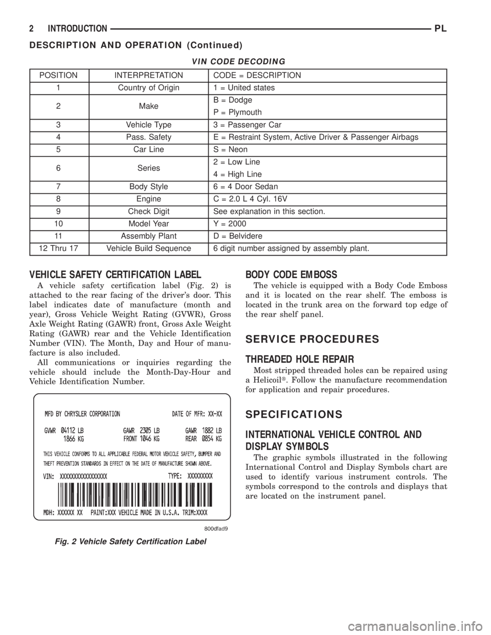
VEHICLE SAFETY CERTIFICATION LABEL
A vehicle safety certification label (Fig. 2) is
attached to the rear facing of the driver's door. This
label indicates date of manufacture (month and
year), Gross Vehicle Weight Rating (GVWR), Gross
Axle Weight Rating (GAWR) front, Gross Axle Weight
Rating (GAWR) rear and the Vehicle Identification
Number (VIN). The Month, Day and Hour of manu-
facture is also included.
All communications or inquiries regarding the
vehicle should include the Month-Day-Hour and
Vehicle Identification Number.
BODY CODE EMBOSS
The vehicle is equipped with a Body Code Emboss
and it is located on the rear shelf. The emboss is
located in the trunk area on the forward top edge of
the rear shelf panel.
SERVICE PROCEDURES
THREADED HOLE REPAIR
Most stripped threaded holes can be repaired using
a Helicoilt. Follow the manufacture recommendation
for application and repair procedures.
SPECIFICATIONS
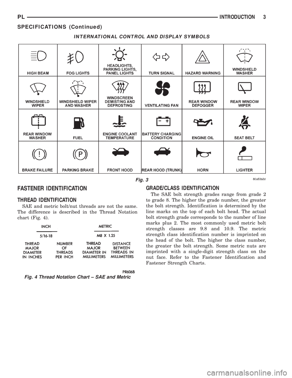
INTERNATIONAL VEHICLE CONTROL AND
DISPLAY SYMBOLS
The graphic symbols illustrated in the following
International Control and Display Symbols chart are
used to identify various instrument controls. The
symbols correspond to the controls and displays that
are located on the instrument panel.
Fig. 2 Vehicle Safety Certification Label
2 INTRODUCTIONPL
DESCRIPTION AND OPERATION (Continued)
Page 1276 of 1285
FASTENER IDENTIFICATION
THREAD IDENTIFICATION
SAE and metric bolt/nut threads are not the same.
The difference is described in the Thread Notation
chart (Fig. 4).
GRADE/CLASS IDENTIFICATION
The SAE bolt strength grades range from grade 2
to grade 8. The higher the grade number, the greater
the bolt strength. Identification is determined by the
line marks on the top of each bolt head. The actual
bolt strength grade corresponds to the number of line
marks plus 2. The most commonly used metric bolt
strength classes are 9.8 and 10.9. The metric
strength class identification number is imprinted on
the head of the bolt. The higher the class number,
the greater the bolt strength. Some metric nuts are
imprinted with a single-digit strength class on the
nut face. Refer to the Fastener Identification and
Fastener Strength Charts.
INTERNATIONAL CONTROL AND DISPLAY SYMBOLS
Fig. 3
Fig. 4 Thread Notation Chart ± SAE and Metric
PLINTRODUCTION 3
SPECIFICATIONS (Continued)