2000 DODGE NEON ESP
[x] Cancel search: ESPPage 236 of 1285
IGNITION SYSTEM
TABLE OF CONTENTS
page page
DESCRIPTION AND OPERATION
IGNITION SYSTEM........................1
SPARK PLUGS...........................1
SPARK PLUG CABLES.....................1
ELECTRONIC IGNITION COILS...............2
AUTOMATIC SHUTDOWN RELAY.............2
CRANKSHAFT POSITION SENSORÐPCM
INPUT................................3
CAMSHAFT POSITION SENSORÐPCM
INPUT................................4
KNOCK SENSOR..........................5
IGNITION SWITCH........................5
LOCK KEY CYLINDER......................5
IGNITION INTERLOCK.....................6
REMOVAL AND INSTALLATION
SPARK PLUG SERVICE....................6SPARK PLUG CABLE SERVICE..............6
IGNITION COIL...........................6
AUTOMATIC SHUTDOWN RELAY.............6
CAMSHAFT POSITION SENSOR..............6
CRANKSHAFT POSITION SENSOR............8
KNOCK SENSOR..........................8
IGNITION SWITCH........................8
LOCK KEY CYLINDER......................9
IGNITION INTERLOCK....................10
SPECIFICATIONS
VECI LABEL............................10
FIRING ORDERÐ2.0L....................10
TORQUE SPECIFICATION..................11
SPARK PLUG CABLE RESISTANCEÐSOHC....11
SPARK PLUG...........................11
IGNITION COIL..........................11
DESCRIPTION AND OPERATION
IGNITION SYSTEM
DESCRIPTION
The system's three main components are the coil
pack, crankshaft position sensor, and camshaft posi-
tion sensor.
OPERATION
Basic ignition timing is not adjustable.The
Powertrain Control Module (PCM) determines spark
advance. The 2.0L engines use a fixed ignition timing
system. The distributorless electronic ignition system
is referred to as the Direct Ignition System (DIS).
SPARK PLUGS
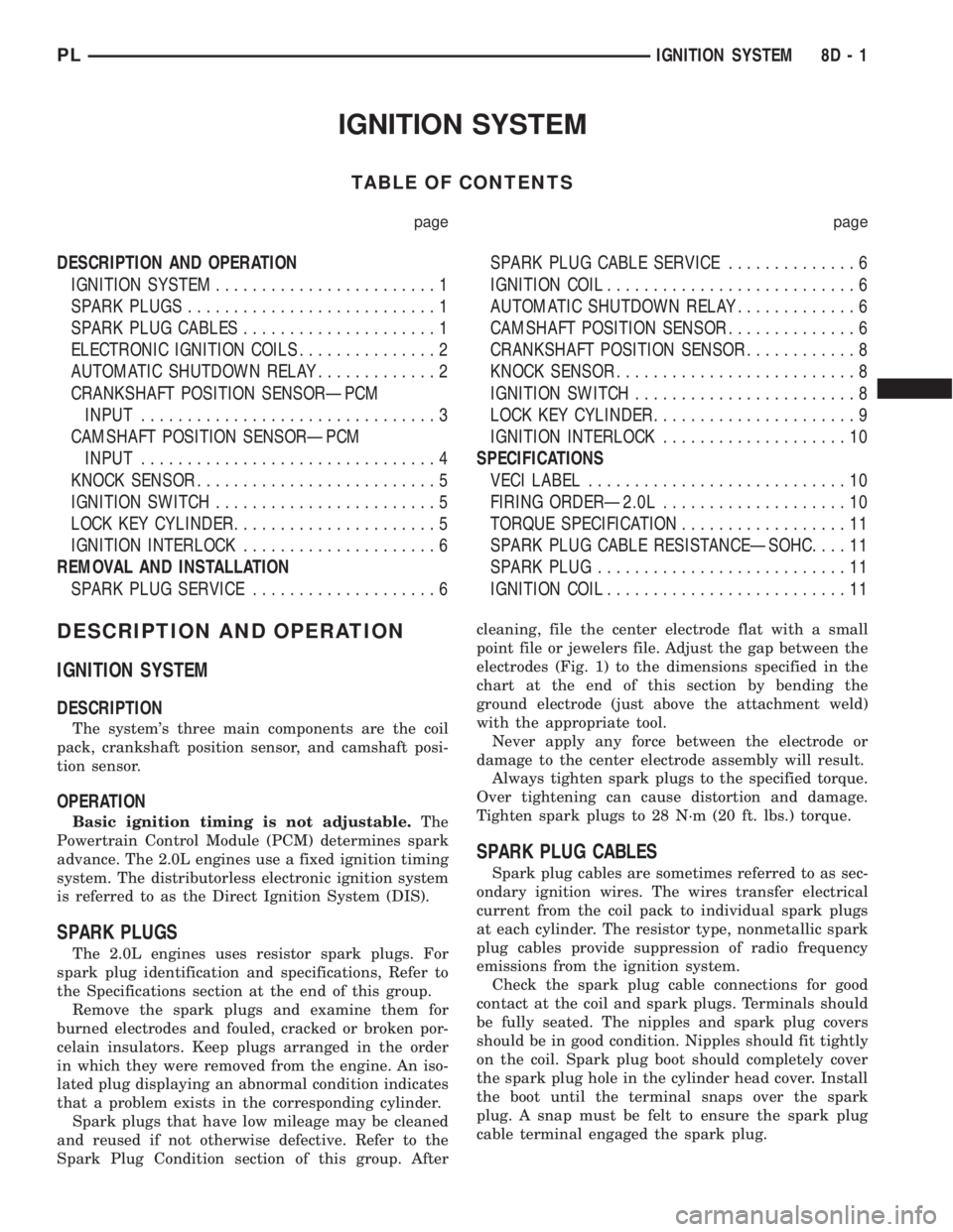
The 2.0L engines uses resistor spark plugs. For
spark plug identification and specifications, Refer to
the Specifications section at the end of this group.
Remove the spark plugs and examine them for
burned electrodes and fouled, cracked or broken por-
celain insulators. Keep plugs arranged in the order
in which they were removed from the engine. An iso-
lated plug displaying an abnormal condition indicates
that a problem exists in the corresponding cylinder.
Spark plugs that have low mileage may be cleaned
and reused if not otherwise defective. Refer to the
Spark Plug Condition section of this group. Aftercleaning, file the center electrode flat with a small
point file or jewelers file. Adjust the gap between the
electrodes (Fig. 1) to the dimensions specified in the
chart at the end of this section by bending the
ground electrode (just above the attachment weld)
with the appropriate tool.
Never apply any force between the electrode or
damage to the center electrode assembly will result.
Always tighten spark plugs to the specified torque.
Over tightening can cause distortion and damage.
Tighten spark plugs to 28 N´m (20 ft. lbs.) torque.
SPARK PLUG CABLES
Spark plug cables are sometimes referred to as sec-
ondary ignition wires. The wires transfer electrical
current from the coil pack to individual spark plugs
at each cylinder. The resistor type, nonmetallic spark
plug cables provide suppression of radio frequency
emissions from the ignition system.
Check the spark plug cable connections for good
contact at the coil and spark plugs. Terminals should
be fully seated. The nipples and spark plug covers
should be in good condition. Nipples should fit tightly
on the coil. Spark plug boot should completely cover
the spark plug hole in the cylinder head cover. Install
the boot until the terminal snaps over the spark
plug. A snap must be felt to ensure the spark plug
cable terminal engaged the spark plug.
PLIGNITION SYSTEM 8D - 1
Page 237 of 1285

Loose cable connections will corrode, increase resis-
tance and permit water to enter the coil towers.
These conditions can cause ignition malfunction.
Plastic clips in various locations protect the cables
from damage. When the cables are replaced the clips
must be used to prevent damage to the cables, and
should be rotated about 30É below the horizontal.
ELECTRONIC IGNITION COILS
DESCRIPTION
The coil pack consists of 2 coils molded together.
The coil pack is mounted on the valve cover (Fig. 2).
OPERATION
WARNING: THE DIRECT IGNITION SYSTEM GEN-
ERATES APPROXIMATELY 40,000 VOLTS. PER-
SONAL INJURY COULD RESULT FROM CONTACT
WITH THIS SYSTEM.
High tension leads route to each cylinder from the
coil. The coil fires two spark plugs every power
stroke. One plug is the cylinder under compression,
the other cylinder fires on the exhaust stroke. Coil
number one fires cylinders 1 and 4. Coil number two
fires cylinders 2 and 3. The PCM determines which
of the coils to charge and fire at the correct time.
The Auto Shutdown (ASD) relay provides battery
voltage to the ignition coil. The PCM provides a
ground contact (circuit) for energizing the coil. When
the PCM breaks the contact, the energy in the coil
primary transfers to the secondary causing thespark. The PCM will de-energize the ASD relay if it
does not receive the crankshaft position sensor and
camshaft position sensor inputs. Refer to Auto Shut-
down (ASD) RelayÐPCM Output, in this section for
relay operation.
AUTOMATIC SHUTDOWN RELAY
DESCRIPTION
The ASD relay is located in the PDC (Fig. 3). The
inside top of the PDC cover has label showing relay
and fuse identification.
Fig. 1 Checking Spark Plug Electrode Gap
1 ± TAPER GAUGE
Fig. 2 Ignition Coil Pack
1 ± IGNITION COILS
2 ± SPARK PLUG CABLE
3 ± SPARK PLUG INSULATOR
Fig. 3 Power Distribution Center (PDC)
8D - 2 IGNITION SYSTEMPL
DESCRIPTION AND OPERATION (Continued)
Page 240 of 1285
KNOCK SENSOR
DESCRIPTION
The knock sensor threads into the cylinder block.
OPERATION
When the knock sensor detects a knock in one of
the cylinders, it sends an input signal to the PCM. In
response, the PCM retards ignition timing for all cyl-
inders by a scheduled amount.Knock sensors contain a piezoelectric material
which constantly vibrates and sends an input voltage
(signal) to the PCM while the engine operates. As the
intensity of the crystal's vibration increases, the
knock sensor output voltage also increases.
NOTE: Over or under tightening affects knock sen-
sor performance, possibly causing improper spark
control.
IGNITION SWITCH
In the RUN position, the ignition switch connects
power from the Power Distribution Center (PDC) to a
fuse in the fuse block, back to a bus bar in the PDC.
The bus bar feeds circuits for the Powertrain Control
Module (PCM), Proportional purge solenoid, EGR
solenoid, and ABS system. The bus bar in the PDC
feeds the coil side of the radiator fan relay, A/C com-
pressor clutch relay, and the fuel pump relay. It also
feeds the Airbag Control Module (ACM)
LOCK KEY CYLINDER
DESCRIPTION
The lock cylinder is inserted in the end of the
housing opposite the ignition switch.
OPERATION
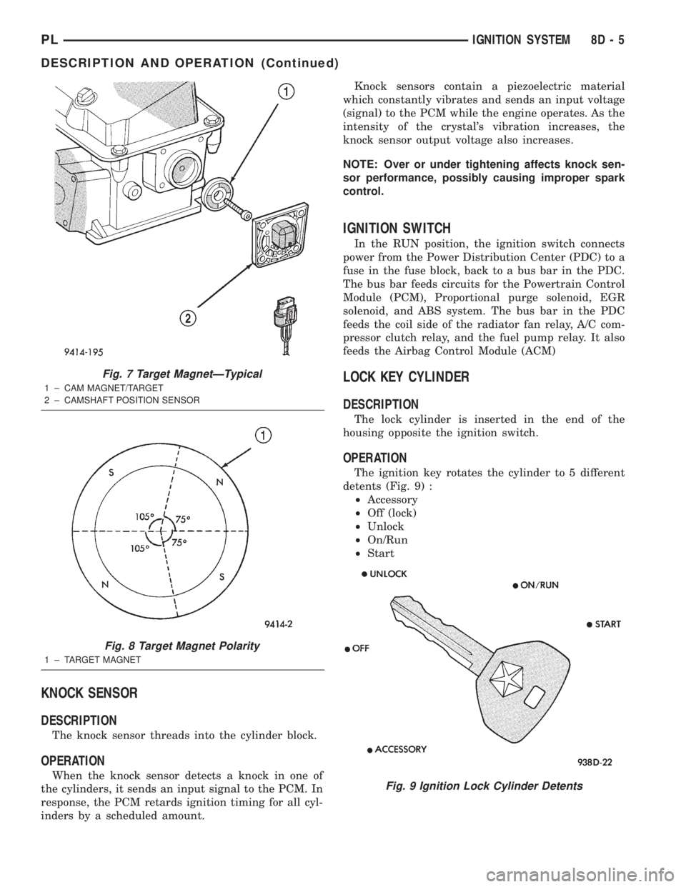
The ignition key rotates the cylinder to 5 different
detents (Fig. 9) :
²Accessory
²Off (lock)
²Unlock
²On/Run
²Start
Fig. 7 Target MagnetÐTypical
1 ± CAM MAGNET/TARGET
2 ± CAMSHAFT POSITION SENSOR
Fig. 8 Target Magnet Polarity
1 ± TARGET MAGNET
Fig. 9 Ignition Lock Cylinder Detents
PLIGNITION SYSTEM 8D - 5
DESCRIPTION AND OPERATION (Continued)
Page 281 of 1285
DIAGNOSIS AND TESTING
HORN
(1) Disconnect wire connector at horn.
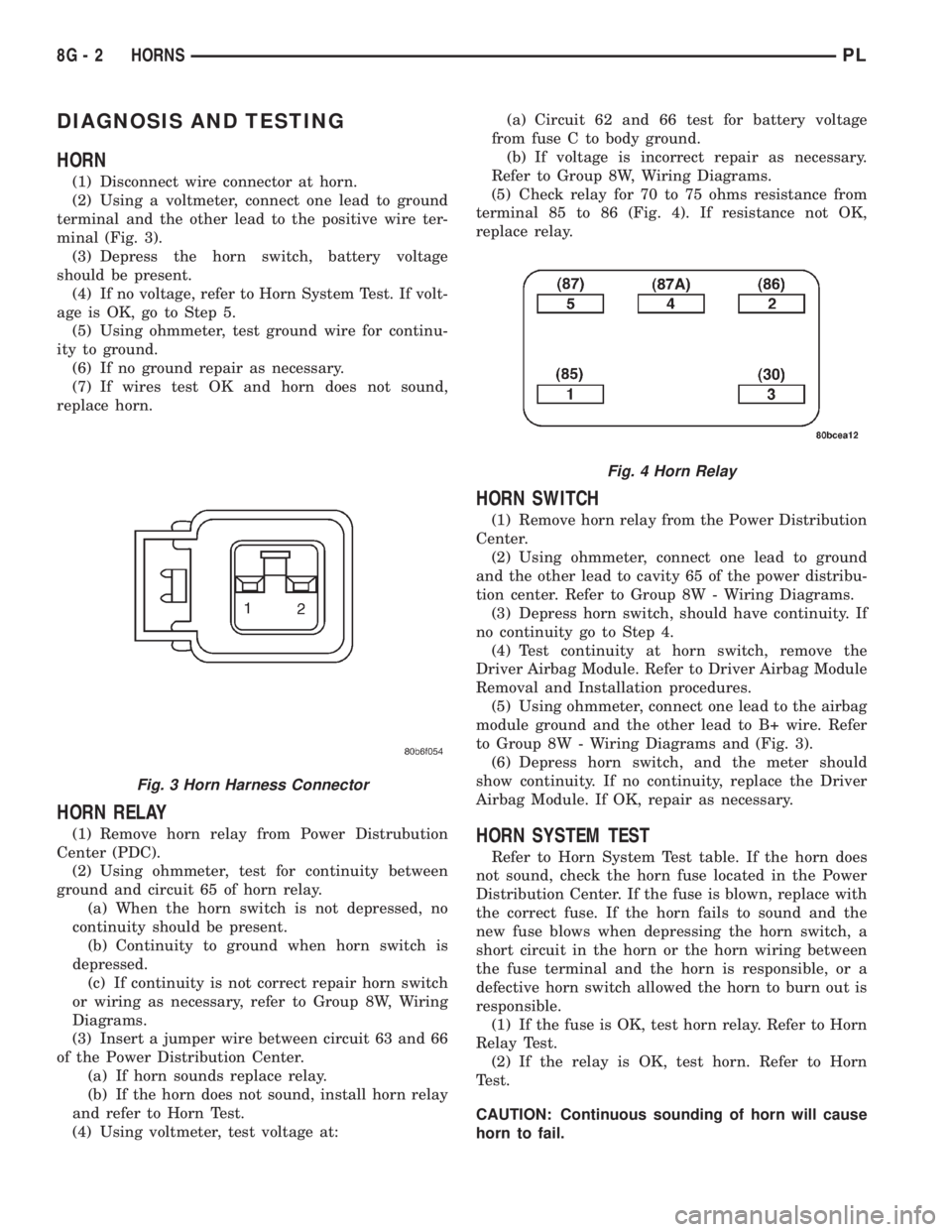
(2) Using a voltmeter, connect one lead to ground
terminal and the other lead to the positive wire ter-
minal (Fig. 3).
(3) Depress the horn switch, battery voltage
should be present.
(4) If no voltage, refer to Horn System Test. If volt-
age is OK, go to Step 5.
(5) Using ohmmeter, test ground wire for continu-
ity to ground.
(6) If no ground repair as necessary.
(7) If wires test OK and horn does not sound,
replace horn.
HORN RELAY
(1) Remove horn relay from Power Distrubution
Center (PDC).
(2) Using ohmmeter, test for continuity between
ground and circuit 65 of horn relay.
(a) When the horn switch is not depressed, no
continuity should be present.
(b) Continuity to ground when horn switch is
depressed.
(c) If continuity is not correct repair horn switch
or wiring as necessary, refer to Group 8W, Wiring
Diagrams.
(3) Insert a jumper wire between circuit 63 and 66
of the Power Distribution Center.
(a) If horn sounds replace relay.
(b) If the horn does not sound, install horn relay
and refer to Horn Test.
(4) Using voltmeter, test voltage at:(a) Circuit 62 and 66 test for battery voltage
from fuse C to body ground.
(b) If voltage is incorrect repair as necessary.
Refer to Group 8W, Wiring Diagrams.
(5) Check relay for 70 to 75 ohms resistance from
terminal 85 to 86 (Fig. 4). If resistance not OK,
replace relay.
HORN SWITCH
(1) Remove horn relay from the Power Distribution
Center.
(2) Using ohmmeter, connect one lead to ground
and the other lead to cavity 65 of the power distribu-
tion center. Refer to Group 8W - Wiring Diagrams.
(3) Depress horn switch, should have continuity. If
no continuity go to Step 4.
(4) Test continuity at horn switch, remove the
Driver Airbag Module. Refer to Driver Airbag Module
Removal and Installation procedures.
(5) Using ohmmeter, connect one lead to the airbag
module ground and the other lead to B+ wire. Refer
to Group 8W - Wiring Diagrams and (Fig. 3).
(6) Depress horn switch, and the meter should
show continuity. If no continuity, replace the Driver
Airbag Module. If OK, repair as necessary.
HORN SYSTEM TEST
Refer to Horn System Test table. If the horn does
not sound, check the horn fuse located in the Power
Distribution Center. If the fuse is blown, replace with
the correct fuse. If the horn fails to sound and the
new fuse blows when depressing the horn switch, a
short circuit in the horn or the horn wiring between
the fuse terminal and the horn is responsible, or a
defective horn switch allowed the horn to burn out is
responsible.
(1) If the fuse is OK, test horn relay. Refer to Horn
Relay Test.
(2) If the relay is OK, test horn. Refer to Horn
Test.
CAUTION: Continuous sounding of horn will cause
horn to fail.
Fig. 3 Horn Harness Connector
Fig. 4 Horn Relay
8G - 2 HORNSPL
Page 288 of 1285
On most vehicles another resistor has been added
to the at rest circuit causing the PCM to never see 5
volts. This was done for diagnostic purposes. If the
switch circuit should open (bad connection) then the
PCM will see the 5 volts and know the circuit is bad.
The PCM will then set an open circuit fault.
STOP LAMP SWITCH
DESCRIPTION
The switch is mounted on the brake pedal mount-
ing bracket under the instrument panel.
OPERATION
Vehicles equipped with the speed control option use
a dual function stop lamp switch. The PCM monitors
the state of the dual function stop lamp switch. Refer
to the Brake section for more information on stop
lamp switch service and adjustment procedures.
The brake switch is equipped with three sets of
contacts, one normally open and the other two nor-
mally closed (brakes disengaged). The PCM sends a
12 volt signal to one of the normally closed contacts
in the brake switch, which is connected to a ground.
With the contacts closed, the 12 volt signal is pulled
to ground causing the signal to go low. The low volt-
age signal, monitored by the PCM, indicates that the
brakes are not applied. When the brakes are applied,
the contacts open, causing the PCM's output voltage
to go high, disengaging the speed control also
grounding the dump solenoid.
The second set of normally closed contacts is sup-
plied battery voltage any time speed control is
selected. From the brake switch, current is routed to
the speed control servo solenoids. The speed control
solenoids (vacuum, vent and dump) are provided this
current any time the speed control is ON and the
brakes are disengaged. When the driver applies the
brakes, the contacts open and current is interrupted
to the solenoids. The normally open contacts are fed
battery voltage. When the brakes are applied, battery
voltage is supplied to the stop lamps.
SERVO CABLE
DESCRIPTION
The speed control servo cable is connected between
the speed control vacuum servo diaphragm and the
throttle body control linkage.
OPERATION
This cable causes the throttle control linkage to
open or close the throttle valve in response to move-
ment of the vacuum servo diaphragm.
VACUUM RESERVOIR
OPERATION
The reservoir stores engine vacuum in the reser-
voir. When engine vacuum drops, as in climbing a
grade while driving, the reservoir supplies the vac-
uum needed to maintain proper speed control opera-
tion. The vacuum reservoir cannot be repaired and
must be replaced if faulty.
VEHICLE SPEED SENSOR
The Vehicle Speed Sensor (VSS) is a pulse genera-
tor mounted to an adapter near the transmission out-
put shaft. The sensor is driven through the adapter
by a speedometer pinion gear. The VSS pulse signal
to the speedometer/odometer is monitored by the
PCM speed control circuitry to determine vehicle
speed and to maintain speed control set speed.
REMOVAL AND INSTALLATION
SPEED CONTROL SERVO
REMOVAL
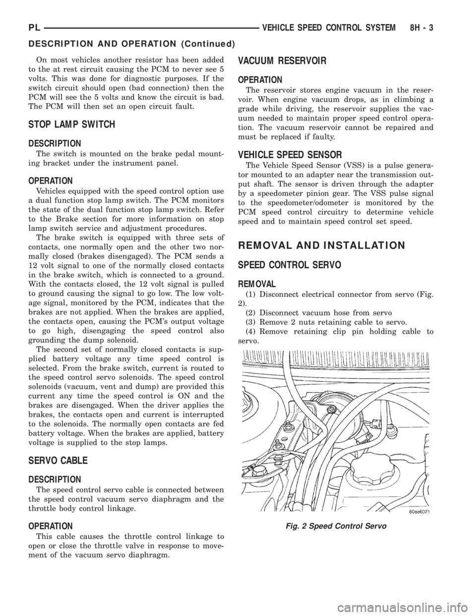
(1) Disconnect electrical connector from servo (Fig.
2).
(2) Disconnect vacuum hose from servo
(3) Remove 2 nuts retaining cable to servo.
(4) Remove retaining clip pin holding cable to
servo.
Fig. 2 Speed Control Servo
PLVEHICLE SPEED CONTROL SYSTEM 8H - 3
DESCRIPTION AND OPERATION (Continued)
Page 364 of 1285
POWER LOCK SYSTEMS
TABLE OF CONTENTS
page page
POWER DOOR LOCKS...................... 1REMOTE KEYLESS ENTRY (RKE).............. 4
POWER DOOR LOCKS
TABLE OF CONTENTS
page page
DESCRIPTION AND OPERATION
INTRODUCTION..........................1
POWER DOOR LOCKS.....................2
CHILD PROTECTION LOCKS................2
DOOR LOCK INHIBIT.......................2
DIAGNOSIS AND TESTING
DOOR LOCK MOTOR......................2
DOOR LOCK SWITCH......................2SERVICE PROCEDURES
DOUBLE ACTIVATION UNLOCK...............3
ROLLING DOOR LOCKS....................3
REMOVAL AND INSTALLATION
DOOR LOCK MOTOR/LATCH.................3
DOOR LOCK SWITCH......................3
REMOTE KEYLESS ENTRY (RKE) MODULE.....3
DESCRIPTION AND OPERATION
INTRODUCTION
All doors can be locked or unlocked electrically by
operating the switch on either front door panel.
When the door lock switch is activated the Remote
Keyless Entry Module provides power to the door
lock motors through relays internal to the module.
The Remote Keyless Entry (RKE) Module also con-
trols the Vehicle Theft Security System (VTSS).
All doors can be locked or unlocked mechanically
and independently with their respective locking
knobs. The front doors can also be unlocked by actu-
ation of the inside remote door handle.
The RKE Module has three modes of operation
including customer usage mode, dealer lot storage
mode, and shipping mode. The customer usage mode
provides full functionality of the module and is the
mode in which the RKE module should be operating
when used by the customer. Dealer lot storage mode
and shipping modes are reduced power modes meant
to extend vehicle battery life during shipping and
storage in the dealer lot. Dealer lot storage mode pro-
vides limited VTSS and power door lock functions,
but disables the Remote Keyless Entry (RKE) func-
tions. This mode is intended to be used when the
vehicle is on the dealer lot to provide VTSS coverageof the vehicle while minimizing battery drain. Ship-
ping mode disables all normal functions (i.e. power
door locks, RKE, and VTSS) of the module, and is
intended to be used when the vehicle is shipped from
the assembly plant.
NOTE: The dealer must remove the module from
ªShip Modeº and place the RKE Module into either
the ªDealer Lotº storage or ªCustomer Usageº
modes of operation after receiving the vehicle from
the assembly plant. Refer to Group 8Q-Vehicle
Theft/Security Systems, Switching Operating
Modes/Configuring a New Module under Service
Procedures.
CENTRAL LOCKING/UNLOCKING
The door locks can be locked or unlocked electri-
cally via the exterior door key cylinders to provide
the central locking/unlocking feature. The central
locking/unlocking feature incorporates a customer
programmable ``Double activation unlockº feature
which operates in the following manner: When
enabled, the first turn of the key cylinder to the
UNLOCK position (toward the front of the vehicle)
will mechanically unlock the door whose key cylinder
is being turned. A second turn of the key cylinder to
the UNLOCK position (within five seconds of the
PLPOWER LOCK SYSTEMS 8P - 1
Page 368 of 1285
NOTE: The dealer must remove the module from
ªShip Modeº and place the RKE Module into either
the ªDealer Lotº storage or ªCustomer Usageº
modes of operation after receiving the vehicle from
the assembly plant. Refer to Group 8Q-Vehicle
Theft/Security Systems, Switching Operating
Modes/Configuring a New Module under Service
Procedures.
REMOTE KEYLESS ENTRY SYSTEM
The system allows locking and unlock of vehicle
door(s) and deck lid by remote control using a hand
held radio frequency (RF) transmitter. The vehicle
speed must be less than five miles per hour before
the deck lid can be unlatched with the transmitter.
The receiver may receive signals from four transmit-
ters. Each transmitter has its own code and the code
has been stored in memory. If the transmitter is
replaced or other transmitters are added, the code for
each unit must be learned.
REMOTE KEYLESS ENTRY TRANSMITTER
The transmitter has four buttons for operation
(Fig. 1). They are LOCK, UNLOCK, DECK LID
RELEASE, and PANIC.
²The UNLOCK button will unlock the driver door
and enable illuminated entry. Pushing and releasing
the button once will unlock the driver door. Pushing
and releasing the button two times within a five sec-
ond period will unlock all doors (double unlock acti-
vation enabled).
²Upon pressing the LOCK button, the horn will
sound a short chirp (if enabled) and flash the park
lamps to notify that the all door lock signal was
received and acted upon. Illuminated entry is can-
celled and the interior lamps are faded to off.
²Pushing and releasing the DECK LID
RELEASE button twice within a five second period
will actuate the decklid release solenoid, causing the
deck lid to be slightly ajar. If so desired, the decklid
may be set to release after one button push by the
dealer. For procedures on programming with the
DRB IIItscan tool, refer to the proper Body Diagnos-
tic Procedures Manual.
²Pushing the PANIC button will cause the panic
alarm to sound for three minutes, until the panic
button is pressed a second time, or until the vehicle
reaches a speed of 15 mph.
HORN CHIRP TOGGLE
Once the transmitters have been programmed, the
horn chirp can be enabled/disabled by sending the
horn chirp toggle operation code to the RKE Module.
This can be done using a DRB IIItscan tool or by
the customer. The horn chirp will enter the oppositestate of its current programmed state by receiving
this operation code. The RKE module is responsible
for keeping track of the horn chirp status.
DIAGNOSIS AND TESTING
REMOTE KEYLESS ENTRY MODULE
For procedures on diagnosing and testing the RKE
Module's RKE functions, refer to the proper Body
Diagnostic Procedures Manual.
DECKLID RELEASE SOLENOID
(1) Confirm operation of RKE transmitter(s) by
actuating Lock and Unlock functions.
(2) Confirm lead is connected to deck lid release
solenoid.
(3) Unplug lead, and use an ohmmeter to verify
continuity of connection between pin 2 of the harness
connector and ground. Refer to Group 8W-Wiring
Diagrams for Connector Pin-Outs.
(4) Connect test light to pin 1 of the harness con-
nector and actuate decklid release button on trans-
mitter. Refer to Group 8W-Wiring Diagrams for
Connector Pin-Outs.
(5) If test light comes on, the wiring circuit
between the RKE module and the solenoid is func-
tional, and the decklid solenoid should be replaced.
(6) If test light does not come on, refer to the
proper Body Diagnostic Procedures Manual for fur-
ther troubleshooting information.
SERVICE PROCEDURES
HORN CHIRP TOGGLE
The toggling of the horn chirp (between enabled
and disabled) can be performed with the use of the
DRB IIItscan tool or by the customer.
DRB lllTPROGRAMMING
When using the DRB IIItscan tool, select:
(1) ªTheft Alarmº
(2) ªVTSSº
(3) ªMiscellaneousº
and then the desired function.
CUSTOMER PROGRAMMING
Using a transmitter programmed to the RKE Mod-
ule, the status of the horn chirp may be toggled by
the customer.
NOTE: The RKE Module is responsible for keeping
track of the horn chirp status; thus this procedure
does not need to be repeated for each transmitter
programmed to the system.
PLPOWER LOCK SYSTEMS 8P - 5
DESCRIPTION AND OPERATION (Continued)
Page 374 of 1285
disarming. The rolling code algorithm ensures secu-
rity by preventing an override of the SKIS through
the unauthorized substitution of the SKIM or the
PCM. However, the use of this strategy also means
that replacement of either the SKIM or the PCM
units will require a system initialization procedure to
restore system operation.
When the ignition switch is turned to the ON or
START positions, the SKIM transmits an RF signal
to excite the Sentry Key transponder. The SKIM then
listens for a return RF signal from the transponder
of the Sentry Key that is inserted in the ignition lock
cylinder. If the SKIM receives an RF signal with
valid ªSecret Keyº and transponder identification
codes, the SKIM then sends a ªvalid keyº message to
the PCM over the PCI bus. If the SKIM receives an
invalid RF signal or no response, it sends ªinvalid
keyº messages to the PCM. The PCM will enable or
disable engine operation based upon the status of the
SKIM messages.
The SKIM also sends messages to the instrument
cluster over the PCI bus network to control the VTSS
indicator LED. The SKIM sends messages to the
instrument cluster to turn the LED on for about
three seconds when the ignition switch is turned to
the ON position as a bulb test. After completion of
the bulb test, the SKIM sends bus messages to keep
the LED off for a duration of about one second. Then
the SKIM sends messages to turn the LED on or off
based upon the results of the SKIS self-tests. If the
VTSS indicator LED comes on and stays on after the
bulb test, it indicates that the SKIM has detected a
system malfunction and/or that the SKIS has become
inoperative.
If the SKIM detects an invalid key when the igni-
tion switch is turned to the ON position, it sends
messages to the instrument cluster to flash the VTSS
indicator LED. The SKIM can also send messages to
the instrument cluster to flash the LED and to gen-
erate a single audible chime tone. These functions
serve as an indication to the customer that the SKIS
has been placed in its ªCustomer Learnº program-
ming mode. See Sentry Key Immobilizer System
Transponder Programming in this group for more
information on the ªCustomer Learnº programming
mode.
For diagnosis or initialization of the SKIM and the
PCM, a DRB IIItscan tool and the proper Body
Diagnostic Procedures Manual are required. The
SKIM cannot be repaired, and if faulty or damaged,
the unit must be replaced.
SENTRY KEY IMMOBILIZER SYSTEM
TRANSPONDER
The Sentry Key Immobilizer System (SKIS) uses a
transponder that is integral to each of three ignitionkey that are supplied with the vehicle when it is
shipped from the factory. The transponder chip is
insulated within a nylon mount inserted in the head
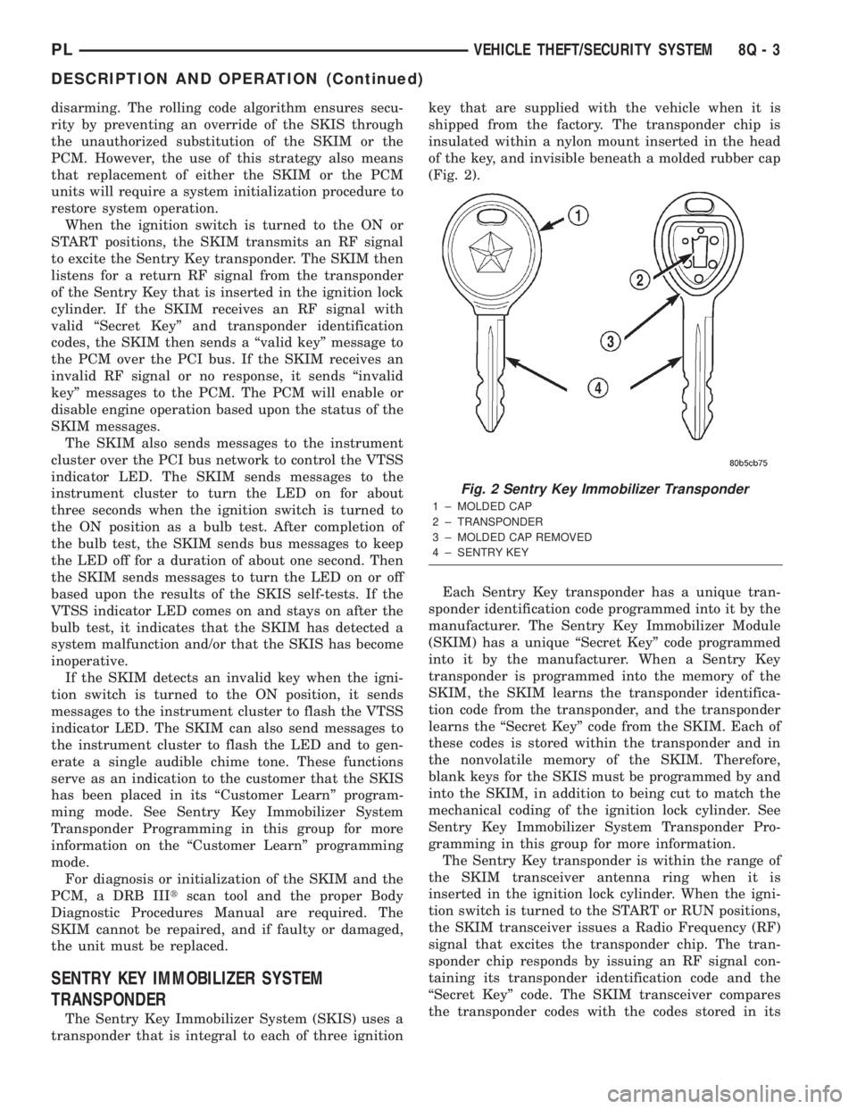
of the key, and invisible beneath a molded rubber cap
(Fig. 2).
Each Sentry Key transponder has a unique tran-
sponder identification code programmed into it by the
manufacturer. The Sentry Key Immobilizer Module
(SKIM) has a unique ªSecret Keyº code programmed
into it by the manufacturer. When a Sentry Key
transponder is programmed into the memory of the
SKIM, the SKIM learns the transponder identifica-
tion code from the transponder, and the transponder
learns the ªSecret Keyº code from the SKIM. Each of
these codes is stored within the transponder and in
the nonvolatile memory of the SKIM. Therefore,
blank keys for the SKIS must be programmed by and
into the SKIM, in addition to being cut to match the
mechanical coding of the ignition lock cylinder. See
Sentry Key Immobilizer System Transponder Pro-
gramming in this group for more information.
The Sentry Key transponder is within the range of
the SKIM transceiver antenna ring when it is
inserted in the ignition lock cylinder. When the igni-
tion switch is turned to the START or RUN positions,
the SKIM transceiver issues a Radio Frequency (RF)
signal that excites the transponder chip. The tran-
sponder chip responds by issuing an RF signal con-
taining its transponder identification code and the
ªSecret Keyº code. The SKIM transceiver compares
the transponder codes with the codes stored in its
Fig. 2 Sentry Key Immobilizer Transponder
1 ± MOLDED CAP
2 ± TRANSPONDER
3 ± MOLDED CAP REMOVED
4 ± SENTRY KEY
PLVEHICLE THEFT/SECURITY SYSTEM 8Q - 3
DESCRIPTION AND OPERATION (Continued)