2000 DODGE NEON air filter
[x] Cancel search: air filterPage 1245 of 1285
POSSIBLE LOCATIONS OR CAUSE OF
OBSTRUCTED COOLANT FLOW
(1) Pinched or kinked heater hoses.
(2) Improper heater hose routing.
(3) Plugged heater hoses or supply and return
ports at cooling system connections, refer to Group 7,
Cooling System.
(4) Plugged heater core.
(5) Air locked heater core.
(6) If coolant flow is verified and outlet tempera-
ture is insufficient, a mechanical problem may exist.
POSSIBLE LOCATION OR CAUSE OF INSUFFICIENT
HEAT
(1) Obstructed cowl air intake.
(2) Obstructed heater system outlets.
(3) Blend-air door not functioning properly.
TEMPERATURE CONTROL
If temperature cannot be adjusted with the TEMP
lever on the control panel, the following could require
service:
(1) Blend-air door binding.
(2) Faulty blend-air door cable.
(3) Improper engine coolant temperature.
(4) Faulty Instrument Panel Control.
LOW PRESSURE CUT OFF SWITCH
The work area must not be below 21ÉC (70ÉF) to
test the compressor clutch circuit.
(1) With gear selector in park or neutral and park
brake set, start engine and allow to idle.
(2) Raise hood and disconnect low pressure cut off
switch connector boot.
(3) Using a suitable jumper wire, jump across the
terminals inside wire connector boot.
(4) If the compressor clutch does not engage, the
cycling clutch switch, wiring, relay, or fuse can be
defective. Refer to Group 8W, Wiring Diagrams.
(5) If clutch engages, connect manifold gauge set.
Read low pressure gauge. At pressure above 97 kPa
(14 psi) and above, low pressure out off switch will
complete the clutch circuit. If the low pressure gauge
reads below 140 kPa (20 psi), the system is low on
refrigerant charge or empty due to a leak. Refer to
Service Procedures, System Leak Checking in this
section.
(6) Install connector boot on switch and repeat
Step 3. If the clutch does not engage, replace the low
pressure cut off switch.
SYSTEM CHARGE LEVEL TEST
The procedure below should be used to check
and/or fill the refrigerant charge in the air condition-
ing system.
WARNING: AVOID BREATHING A/C REFRIGERANT
AND LUBRICANT VAPOR OR MIST. EXPOSURE MAY
IRRITATE EYES, NOSE AND THROAT. USE ONLY
APPROVED SERVICE EQUIPMENT MEETING SAE
REQUIREMENTS TO DISCHARGE R-134a SYSTEM.
IF ACCIDENTAL SYSTEM DISCHARGE OCCURS,
VENTILATE WORK AREA BEFORE RESUMING SER-
VICE.
R-134a SERVICE EQUIPMENT OR VEHICLE A/C
SYSTEM SHOULD NOT BE PRESSURE TESTED OR
LEAK TESTED WITH COMPRESSED AIR. MIXTURE
OF AIR and R-134a CAN BE COMBUSTIBLE AT ELE-
VATED PRESSURES. THESE MIXTURES ARE
POTENTIALLY DANGEROUS AND MAY RESULT IN
FIRE OR EXPLOSION CAUSING INJURY OR PROP-
ERTY DAMAGE.
NOTE: The maximum amount of R-134a refrigerant
that the air conditioning system holds is 765 grams
(27 oz. or 1.69 lbs.)
It is recommended to use the gauges or reclaim/re-
cycle equipment.
(1) Use a manifold gauge and check the liquid line
pressure.
(2) Attach a clamp-on thermocouple (P. S. E.
66-324-0014 or 80PK-1A) or equivalent to the liquid
line near the filter/drier.
(3) The vehicle must be in the following modes:
²Automatic transaxle in park or manual tran-
saxle in neutral.
²Engine at idle
²A/C controls set to outside air
²Panel mode
²A/C ON full cool
²Blower motor ON high speed
²Vehicle windows closed
(4) Operate system for a couple of minutes to allow
the system to stabilize.
(5) Observe filter/drier pressure and Liquid line
temperature. Using the Charge Determination Chart
(Fig. 14) determine where the system is currently
operating. If the system is not in the proper range,
reclaim all the refrigerant and recharge per A/C
label.
24 - 14 HEATING AND AIR CONDITIONINGPL
DIAGNOSIS AND TESTING (Continued)
Page 1248 of 1285
gauge should return to the calibrated setting of 27
kPa (8 in. Hg.). If not there is a leak in the Actuator
Feed line.
(8) If there is no leak in the Supply line, Control,
or the Actuator Feed line, the leak must be in the
Actuator itself. Connect the Vacuum hose from the
Vacuum Test Gauge directly to the Actuator to verify
the leak.
LOCATING PINCHED VACUUM LINES
The operation of the Circulation door can be
viewed by removing the blower motor and looking up
into the unit inlet. See Blower Motor Wheel and
Assembly removal and installation in this section for
service procedures.
(1) Connect the test vacuum probe to the vehicles
(Black) supply hose. Position the vacuum test gauge
so it can be viewed from the passenger compartment.
(2) Place the Mode in the Panel position and the
Circulation control in the Recirculation position.
(3) Remove the center instrument panel bezel.
(4) Remove the center vent duct.
(5) Remove the Supply (Black) vacuum line at the
control. The test gauge should drop indicating free
flow through the Supply line. If not, there is a block-
age in the Supply line.
(6) If there is no blockage in the Supply line,
reconnect it to the Control. Remove the Actuator
Feed (Red) line from the Control. The test gauge
should drop indicating free flow through the Supply
line and Control. If not the vacuum switches on the
Control are not functioning.
(7) If there is no blockage in the Supply line or the
Control, reconnect the Actuator Feed (Red) line to the
control. Remove the Actuator Feed (Red) line at the
Actuator. The Actuator vacuum port is accessible
behind and above the Glove Box. The test gauge
should drop indicating free flow through the supply
line, Control, and the Actuator Feed line. If not,
there is a blockage in the Actuator Feed line.
(8) If there is no blockage in the Supply line, Con-
trol, or the Actuator Feed line, the Actuator must
have failed. Connect the Vacuum hose from the Vac-
uum Test Gauge directly to the Actuator to verify the
Actuator has failed.
SERVICE PROCEDURES
CHARGING A/C SYSTEM
PARTIAL CHARGE
This vehicle does not have a sight glass. It is not
possible to determine the amount of (R-134a) charge
in the system. Therefore it is necessary to completely
evacuate and recover the system, and then recharge
the system fully.
EVACUATION
Before adding refrigerant, all air must be evacu-
ated from the system.
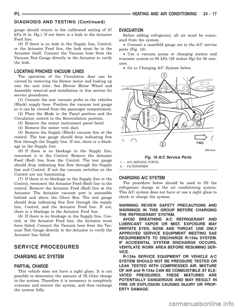
²Connect a manifold gauge set to the A/C service
ports (Fig. 16).
²Use a vacuum pump or charging station and
evacuate system to 95 kPa (28 inches Hg) for 30 min-
utes.
²Go to Charging A/C System below.
CHARGING A/C SYSTEM
The procedure below should be used to fill the
refrigerant charge in the air conditioning system.
This A/C system does not have or use a sight glass to
check or charge the system.
WARNING: REVIEW SAFETY PRECAUTIONS AND
WARNINGS IN THIS GROUP BEFORE CHARGING
THE REFRIGERANT SYSTEM.
AVOID BREATHING A/C REFRIGERANT AND
LUBRICANT VAPOR OR MIST. EXPOSURE MAY
IRRITATE EYES, NOSE AND THROAT. USE ONLY
APPROVED SERVICE EQUIPMENT MEETING SAE
REQUIREMENTS TO DISCHARGE R-134a SYSTEM.
IF ACCIDENTAL SYSTEM DISCHARGE OCCURS,
VENTILATE WORK AREA BEFORE RESUMING SER-
VICE.
R-134a SERVICE EQUIPMENT OR VEHICLE A/C
SYSTEM SHOULD NOT BE PRESSURE TESTED OR
LEAK TESTED WITH COMPRESSED AIR. MIXTURE
OF AIR and R-134a CAN BE COMBUSTIBLE AT ELE-
VATED PRESSURES. THESE MIXTURES ARE
POTENTIALLY DANGEROUS AND MAY RESULT IN
FIRE OR EXPLOSION CAUSING INJURY OR PROP-
ERTY DAMAGE.
Fig. 16 A/C Service Ports
1 ± A/C SERVICE PORTS
2 ± FILTER/DRIER
PLHEATING AND AIR CONDITIONING 24 - 17
DIAGNOSIS AND TESTING (Continued)
Page 1250 of 1285
Then allow the system to evacuate an additional 10
minutes.
(3) Close all valves. Turn off and disconnect the
vacuum pump.
(4) The refrigerant system is prepared to be
charged with refrigerant.
R-134a REFRIGERANT
This vehicle uses a refrigerant called R-134a. It is
a non-toxic, non-flammable, clear colorless liquefied
gas.
R-134a refrigerant is not compatible with R-12
refrigerant in an air conditioning system. Even a
small amount of R-12 in a R-134a system could cause
compressor failure, refrigerant oil to sludge and/or
poor performance.Never add any other type of
refrigerant to a system designed to use R-134a
refrigerant. System failure will occur.
The high pressure service port is located on the
ffilter/drier. The low pressure service port is located
on the suction line near the strut tower.
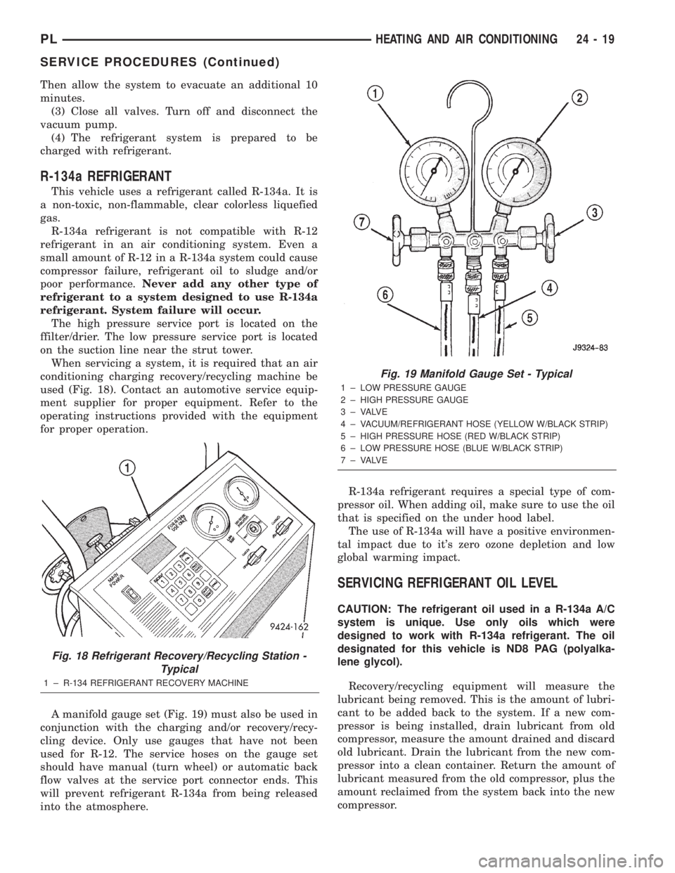
When servicing a system, it is required that an air
conditioning charging recovery/recycling machine be
used (Fig. 18). Contact an automotive service equip-
ment supplier for proper equipment. Refer to the
operating instructions provided with the equipment
for proper operation.
A manifold gauge set (Fig. 19) must also be used in
conjunction with the charging and/or recovery/recy-
cling device. Only use gauges that have not been
used for R-12. The service hoses on the gauge set
should have manual (turn wheel) or automatic back
flow valves at the service port connector ends. This
will prevent refrigerant R-134a from being released
into the atmosphere.R-134a refrigerant requires a special type of com-
pressor oil. When adding oil, make sure to use the oil
that is specified on the under hood label.
The use of R-134a will have a positive environmen-
tal impact due to it's zero ozone depletion and low
global warming impact.
SERVICING REFRIGERANT OIL LEVEL
CAUTION: The refrigerant oil used in a R-134a A/C
system is unique. Use only oils which were
designed to work with R-134a refrigerant. The oil
designated for this vehicle is ND8 PAG (polyalka-
lene glycol).
Recovery/recycling equipment will measure the
lubricant being removed. This is the amount of lubri-
cant to be added back to the system. If a new com-
pressor is being installed, drain lubricant from old
compressor, measure the amount drained and discard
old lubricant. Drain the lubricant from the new com-
pressor into a clean container. Return the amount of
lubricant measured from the old compressor, plus the
amount reclaimed from the system back into the new
compressor.
Fig. 18 Refrigerant Recovery/Recycling Station -
Typical
1 ± R-134 REFRIGERANT RECOVERY MACHINE
Fig. 19 Manifold Gauge Set - Typical
1 ± LOW PRESSURE GAUGE
2 ± HIGH PRESSURE GAUGE
3 ± VALVE
4 ± VACUUM/REFRIGERANT HOSE (YELLOW W/BLACK STRIP)
5 ± HIGH PRESSURE HOSE (RED W/BLACK STRIP)
6 ± LOW PRESSURE HOSE (BLUE W/BLACK STRIP)
7 ± VALVE
PLHEATING AND AIR CONDITIONING 24 - 19
SERVICE PROCEDURES (Continued)
Page 1251 of 1285
(1) Discharge refrigerant system using recovery/re-
cycling equipment if charge is present.
(2) Disconnect refrigerant lines from A/C compres-
sor. Cap the open lines to prevent moisture from
entering system.
(3) Remove compressor from vehicle.
(4) From suction port on top of compressor, drain
lubricant from compressor.
(5) Add system capacity minus the capacity of
components that have not been replaced. Refer to the
Lubricant Capacity Chart. Add lubricant through the
suction port on compressor. This is not to exceed 180
ml (6.10 oz.) in total.
(6) Install compressor and connect refrigerant
lines. Then evacuate and charge refrigerant system.
SYSTEM LEAK CHECKING
WARNING: R-134a SERVICE EQUIPMENT OR VEHI-
CLE A/C SYSTEM SHOULD NOT BE PRESSURE
TESTED OR LEAK TESTED WITH COMPRESSED
AIR. MIXTURE OF AIR and R-134a CAN BE COM-
BUSTIBLE AT ELEVATED PRESSURES. THESE MIX-
TURES ARE POTENTIALLY DANGEROUS AND MAY
RESULT IN FIRE OR EXPLOSION CAUSING INJURY
OR PROPERTY DAMAGE.
AVOID BREATHING A/C REFRIGERANT AND
LUBRICANT VAPOR OR MIST. EXPOSURE MAY
IRRITATE EYES, NOSE AND THROAT. USE ONLY
APPROVED SERVICE EQUIPMENT MEETING SAE
REQUIREMENTS TO DISCHARGE R-134a SYSTEM.
IF ACCIDENTAL SYSTEM DISCHARGE OCCURS,
VENTILATE WORK AREA BEFORE RESUMING SER-
VICE.
If the A/C system is not cooling properly, determine
if the refrigerant system is fully charged with
R-134a. This is accomplished by performing a system
Charge Level-Check or Fill. If while performing this
test A/C liquid line pressure is less than 345 kPa (50
psi) proceed to Empty Refrigerant System Leak Test.
If liquid line pressure is greater than 345 kPa (50
psi) proceed to low refrigerant level leak test. If the
refrigerant system is empty or low in refrigerant
charge, a leak at any line fitting or component seal is
likely. A review of the fittings, lines and components
for oily residue is an indication of the leak location.
To detect a leak in the refrigerant system, perform
one of the following procedures as indicated by the
symptoms.
EMPTY REFRIGERANT SYSTEM LEAK TEST
(1) Evacuate the refrigerant system to the lowest
degree of vacuum possible (approx. 28 in Hg.). Deter-
mine if the system holds a vacuum for 15 minutes. If
vacuum is held, a leak is probably not present. If sys-tem will not maintain vacuum level, proceed with
this procedure.
(2) Prepare a.284 Kg. (10 oz.) refrigerant charge to
be injected into the system.
(3) Connect and dispense.284 Kg. (10 oz.) of refrig-
erant into the evacuated refrigerant system.
(4) Proceed to Step 2 of Low Refrigerant Level
Leak Test.
LOW REFRIGERANT LEVEL LEAK TEST
(1) Determine if there is any (R-134a) refrigerant
in the system.
(2) Position the vehicle in a wind free work area.
This will aid in detecting small leaks.
(3) Bring the refrigerant system up to operating
temperature and pressure. This is done by allowing
the engine to run for five minutes with the system
set to the following:
²Transaxle in Park
²Engine Idling at 700 rpm
²A/C Controls Set in 100 percent outside air
²Blower switch in the high A/C position
²A/C in the ON position
²Open all windows
CAUTION: A leak detector designed for R-12 refrig-
erant (only) will not detect leaks in a R-134a refrig-
erant system.
(4) Shut off the vehicle and wait 2 to 7 minutes.
Then use an Electronic Leak Detector that is
designed to detect R-134a type refrigerant and search
for leaks. Fittings, lines, or components that appear
to be oily usually indicates a refrigerant leak. To
inspect the evaporator core for leaks, insert the leak
detector probe into the drain tube opening or a heat
duct. A R-134a dye is available to aid in leak detec-
tion, use only Chrysler approved refrigerant dye.
If a thorough leak check has been completed with-
out indication of a leak, proceed to System Charge
Level.
REMOVAL AND INSTALLATION
A/C FILTER/DRIER
The filter/drier is mounted in a rubber grommet on
the right side of the engine compartment. The refrig-
erant must be recovered from the A/C system before
replacing the filter/drier assembly.
WARNING: THE REFRIGERATION SYSTEM MUST
BE COMPLETELY RECOVERED BEFORE PRO-
CEEDING WITH THIS OPERATION.
24 - 20 HEATING AND AIR CONDITIONINGPL
SERVICE PROCEDURES (Continued)
Page 1252 of 1285
REMOVAL
(1) Disconnect liquid line from filter/drier.
(2) Disconnect liquid line on suction line assembly
from filter/drier.
(3) Pull filter/drier out of rubber grommet.
INSTALLATION
For installation, reverse the above procedures.
A/C SERVICE PORT VALVE CORES
REMOVAL
(1) Remove the valve caps (Fig. 4).
(2) Using a R-134a refrigerant recovery machine,
Remove the refrigerant from A/C system.
(3) Using a standard valve core tool, remove the
valve core.Be careful to prevent any dirt/debris
from entering the valve core opening or getting
on the replacement valve core.
INSTALLATION
(1) When assembling the new valve core into the
port, the core should be oiled with clean ND8 PAG
compressor oil.
CAUTION: A valve that is not fully seated can lead
to damage to the valve during evacuation and
charge. This can result in system refrigerant dis-
charge while uncoupling the charge adapters.
(2) Install valve core into port.
(3) Evacuate and charge the A/C system.
(4) Install the valve caps.
BLOWER MOTOR AND WHEEL ASSEMBLY
The blower motor is located on the bottom right
side of the unit housing. The blower motor can be
removed from the vehicle without having to remove
the unit housing assembly.
WITH AIR CONDITIONING
REMOVAL
(1) Remove right side scuff plate.
(2) Pull back carpet.
(3) Disconnect blower motor wiring connector.
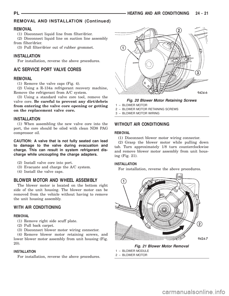
(4) Remove blower motor retaining screws, and
lower blower motor assembly from unit housing (Fig.
20).
INSTALLATION
For installation, reverse the above procedures.
WITHOUT AIR CONDITIONING
REMOVAL
(1) Disconnect blower motor wiring connector.
(2) Grasp the blower motor while pulling down
tab. Turn approximately 1/8 turn counterclockwise
and remove blower motor assembly from unit hous-
ing (Fig. 21).
INSTALLATION
For installation, reverse the above procedures.
Fig. 20 Blower Motor Retaining Screws
1 ± BLOWER MOTOR
2 ± BLOWER MOTOR RETAINING SCREWS
3 ± BLOWER MOTOR WIRING
Fig. 21 Blower Motor Removal
1 ± BLOWER MODULE
2 ± BLOWER MOTOR
PLHEATING AND AIR CONDITIONING 24 - 21
REMOVAL AND INSTALLATION (Continued)
Page 1254 of 1285
(8) Remove compressor. If refrigerant lines were
not removed, lift compressor/clutch assembly and tie
it to a suitable component.
INSTALLATION
For installation, reverse the above procedures.
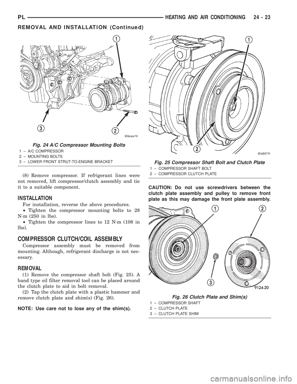
²Tighten the compressor mounting bolts to 28
N´m (250 in lbs).
²Tighten the compressor lines to 12 N´m (108 in
lbs).
COMPRESSOR CLUTCH/COIL ASSEMBLY
Compressor assembly must be removed from
mounting. Although, refrigerant discharge is not nec-
essary.
REMOVAL
(1) Remove the compressor shaft bolt (Fig. 25). A
band type oil filter removal tool can be placed around
the clutch plate to aid in bolt removal.
(2) Tap the clutch plate with a plastic hammer and
remove clutch plate and shim(s) (Fig. 26).
NOTE: Use care not to lose any of the shim(s).CAUTION: Do not use screwdrivers between the
clutch plate assembly and pulley to remove front
plate as this may damage the front plate assembly.
Fig. 24 A/C Compressor Mounting Bolts
1 ± A/C COMPRESSOR
2 ± MOUNTING BOLTS
3 ± LOWER FRONT STRUT-TO-ENGINE BRACKET
Fig. 25 Compressor Shaft Bolt and Clutch Plate
1 ± COMPRESSOR SHAFT BOLT
2 ± COMPRESSOR CLUTCH PLATE
Fig. 26 Clutch Plate and Shim(s)
1 ± COMPRESSOR SHAFT
2 ± CLUTCH PLATE
3 ± CLUTCH PLATE SHIM
PLHEATING AND AIR CONDITIONING 24 - 23
REMOVAL AND INSTALLATION (Continued)
Page 1263 of 1285
(3) Remove line at expansion valve.
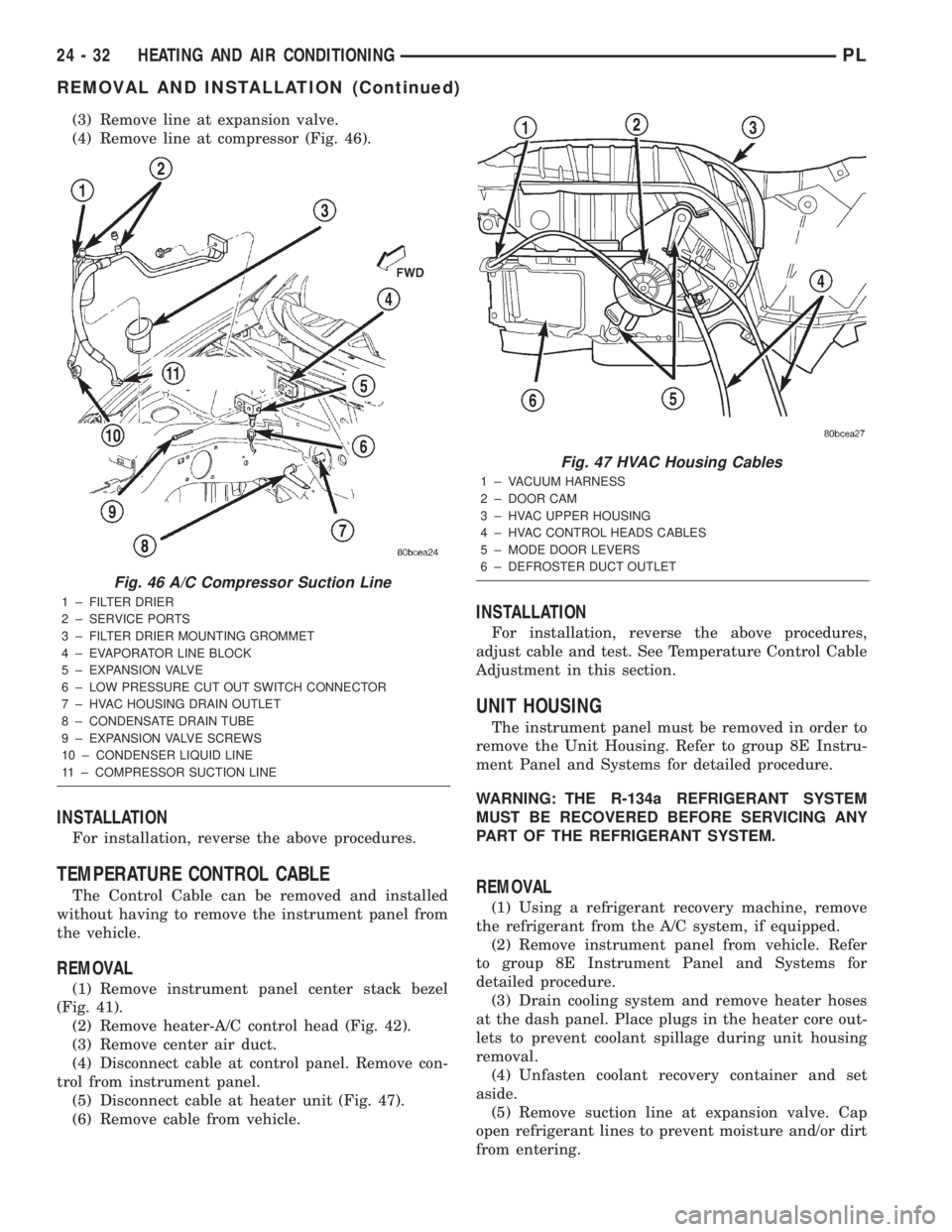
(4) Remove line at compressor (Fig. 46).
INSTALLATION
For installation, reverse the above procedures.
TEMPERATURE CONTROL CABLE
The Control Cable can be removed and installed
without having to remove the instrument panel from
the vehicle.
REMOVAL
(1) Remove instrument panel center stack bezel
(Fig. 41).
(2) Remove heater-A/C control head (Fig. 42).
(3) Remove center air duct.
(4) Disconnect cable at control panel. Remove con-
trol from instrument panel.
(5) Disconnect cable at heater unit (Fig. 47).
(6) Remove cable from vehicle.
INSTALLATION
For installation, reverse the above procedures,
adjust cable and test. See Temperature Control Cable
Adjustment in this section.
UNIT HOUSING
The instrument panel must be removed in order to
remove the Unit Housing. Refer to group 8E Instru-
ment Panel and Systems for detailed procedure.
WARNING: THE R-134a REFRIGERANT SYSTEM
MUST BE RECOVERED BEFORE SERVICING ANY
PART OF THE REFRIGERANT SYSTEM.
REMOVAL
(1) Using a refrigerant recovery machine, remove
the refrigerant from the A/C system, if equipped.
(2) Remove instrument panel from vehicle. Refer
to group 8E Instrument Panel and Systems for
detailed procedure.
(3) Drain cooling system and remove heater hoses
at the dash panel. Place plugs in the heater core out-
lets to prevent coolant spillage during unit housing
removal.
(4) Unfasten coolant recovery container and set
aside.
(5) Remove suction line at expansion valve. Cap
open refrigerant lines to prevent moisture and/or dirt
from entering.
Fig. 46 A/C Compressor Suction Line
1 ± FILTER DRIER
2 ± SERVICE PORTS
3 ± FILTER DRIER MOUNTING GROMMET
4 ± EVAPORATOR LINE BLOCK
5 ± EXPANSION VALVE
6 ± LOW PRESSURE CUT OUT SWITCH CONNECTOR
7 ± HVAC HOUSING DRAIN OUTLET
8 ± CONDENSATE DRAIN TUBE
9 ± EXPANSION VALVE SCREWS
10 ± CONDENSER LIQUID LINE
11 ± COMPRESSOR SUCTION LINE
Fig. 47 HVAC Housing Cables
1 ± VACUUM HARNESS
2 ± DOOR CAM
3 ± HVAC UPPER HOUSING
4 ± HVAC CONTROL HEADS CABLES
5 ± MODE DOOR LEVERS
6 ± DEFROSTER DUCT OUTLET
24 - 32 HEATING AND AIR CONDITIONINGPL
REMOVAL AND INSTALLATION (Continued)