2000 DODGE NEON air filter
[x] Cancel search: air filterPage 1063 of 1285
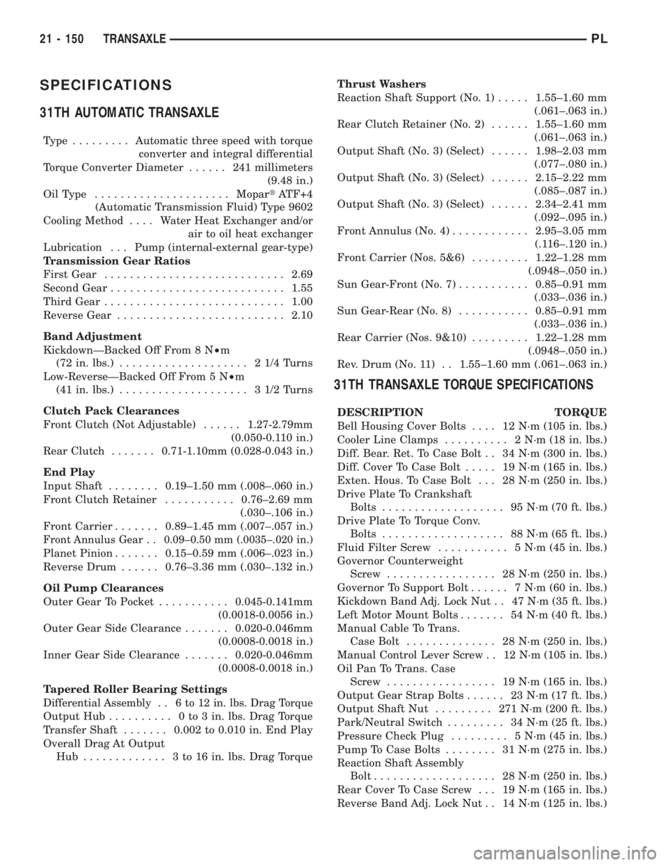
SPECIFICATIONS
31TH AUTOMATIC TRANSAXLE
Type .........Automatic three speed with torque
converter and integral differential
Torque Converter Diameter...... 241millimeters
(9.48 in.)
OilType .....................MopartATF+4
(Automatic Transmission Fluid) Type 9602
Cooling Method.... Water Heat Exchanger and/or
air to oil heat exchanger
Lubrication . . . Pump (internal-external gear-type)
Transmission Gear Ratios
First Gear............................2.69
Second Gear...........................1.55
Third Gear............................1.00
Reverse Gear..........................2.10
Band Adjustment
KickdownÐBacked Off From 8 N²m
(72 in. lbs.).................... 21/4Turns
Low-ReverseÐBacked Off From 5 N²m
(41 in. lbs.).................... 31/2Turns
Clutch Pack Clearances
Front Clutch (Not Adjustable)......1.27-2.79mm
(0.050-0.110 in.)
Rear Clutch.......0.71-1.10mm (0.028-0.043 in.)
End Play
Input Shaft........0.19±1.50 mm (.008±.060 in.)
Front Clutch Retainer...........0.76±2.69 mm
(.030±.106 in.)
Front Carrier.......0.89±1.45 mm (.007±.057 in.)
Front Annulus Gear . . 0.09±0.50 mm (.0035±.020 in.)
Planet Pinion.......0.15±0.59 mm (.006±.023 in.)
Reverse Drum......0.76±3.36 mm (.030±.132 in.)
Oil Pump Clearances
Outer Gear To Pocket...........0.045-0.141mm
(0.0018-0.0056 in.)
Outer Gear Side Clearance.......0.020-0.046mm
(0.0008-0.0018 in.)
Inner Gear Side Clearance.......0.020-0.046mm
(0.0008-0.0018 in.)
Tapered Roller Bearing Settings
Differential Assembly . . 6 to 12 in. lbs. Drag Torque
Output Hub.......... 0to3in.lbs. Drag Torque
Transfer Shaft.......0.002 to 0.010 in. End Play
Overall Drag At Output
Hub ............. 3to16in.lbs. Drag TorqueThrust Washers
Reaction Shaft Support (No. 1).....1.55±1.60 mm
(.061±.063 in.)
Rear Clutch Retainer (No. 2)......1.55±1.60 mm
(.061±.063 in.)
Output Shaft (No. 3) (Select)......1.98±2.03 mm
(.077±.080 in.)
Output Shaft (No. 3) (Select)......2.15±2.22 mm
(.085±.087 in.)
Output Shaft (No. 3) (Select)......2.34±2.41 mm
(.092±.095 in.)
Front Annulus (No. 4)............2.95±3.05 mm
(.116±.120 in.)
Front Carrier (Nos. 5&6).........1.22±1.28 mm
(.0948±.050 in.)
Sun Gear-Front (No. 7)...........0.85±0.91 mm
(.033±.036 in.)
Sun Gear-Rear (No. 8)...........0.85±0.91 mm
(.033±.036 in.)
Rear Carrier (Nos. 9&10).........1.22±1.28 mm
(.0948±.050 in.)
Rev. Drum (No. 11) . . 1.55±1.60 mm (.061±.063 in.)
31TH TRANSAXLE TORQUE SPECIFICATIONS
DESCRIPTION TORQUE
Bell Housing Cover Bolts.... 12N´m(105 in. lbs.)
Cooler Line Clamps.......... 2N´m(18in.lbs.)
Diff. Bear. Ret. To Case Bolt . . 34 N´m (300 in. lbs.)
Diff. Cover To Case Bolt..... 19N´m(165 in. lbs.)
Exten. Hous. To Case Bolt . . . 28 N´m (250 in. lbs.)
Drive Plate To Crankshaft
Bolts................... 95N´m(70ft.lbs.)
Drive Plate To Torque Conv.
Bolts................... 88N´m(65ft.lbs.)
Fluid Filter Screw........... 5N´m(45in.lbs.)
Governor Counterweight
Screw................. 28N´m(250 in. lbs.)
Governor To Support Bolt...... 7N´m(60in.lbs.)
Kickdown Band Adj. Lock Nut . . 47 N´m (35 ft. lbs.)
Left Motor Mount Bolts....... 54N´m(40ft.lbs.)
Manual Cable To Trans.
Case Bolt.............. 28N´m(250 in. lbs.)
Manual Control Lever Screw . . 12 N´m (105 in. lbs.)
Oil Pan To Trans. Case
Screw................. 19N´m(165 in. lbs.)
Output Gear Strap Bolts...... 23N´m(17ft.lbs.)
Output Shaft Nut......... 271N´m(200 ft. lbs.)
Park/Neutral Switch......... 34N´m(25ft.lbs.)
Pressure Check Plug......... 5N´m(45in.lbs.)
Pump To Case Bolts........ 31N´m(275 in. lbs.)
Reaction Shaft Assembly
Bolt................... 28N´m(250 in. lbs.)
Rear Cover To Case Screw . . . 19 N´m (165 in. lbs.)
Reverse Band Adj. Lock Nut . . 14 N´m (125 in. lbs.)
21 - 150 TRANSAXLEPL
Page 1110 of 1285
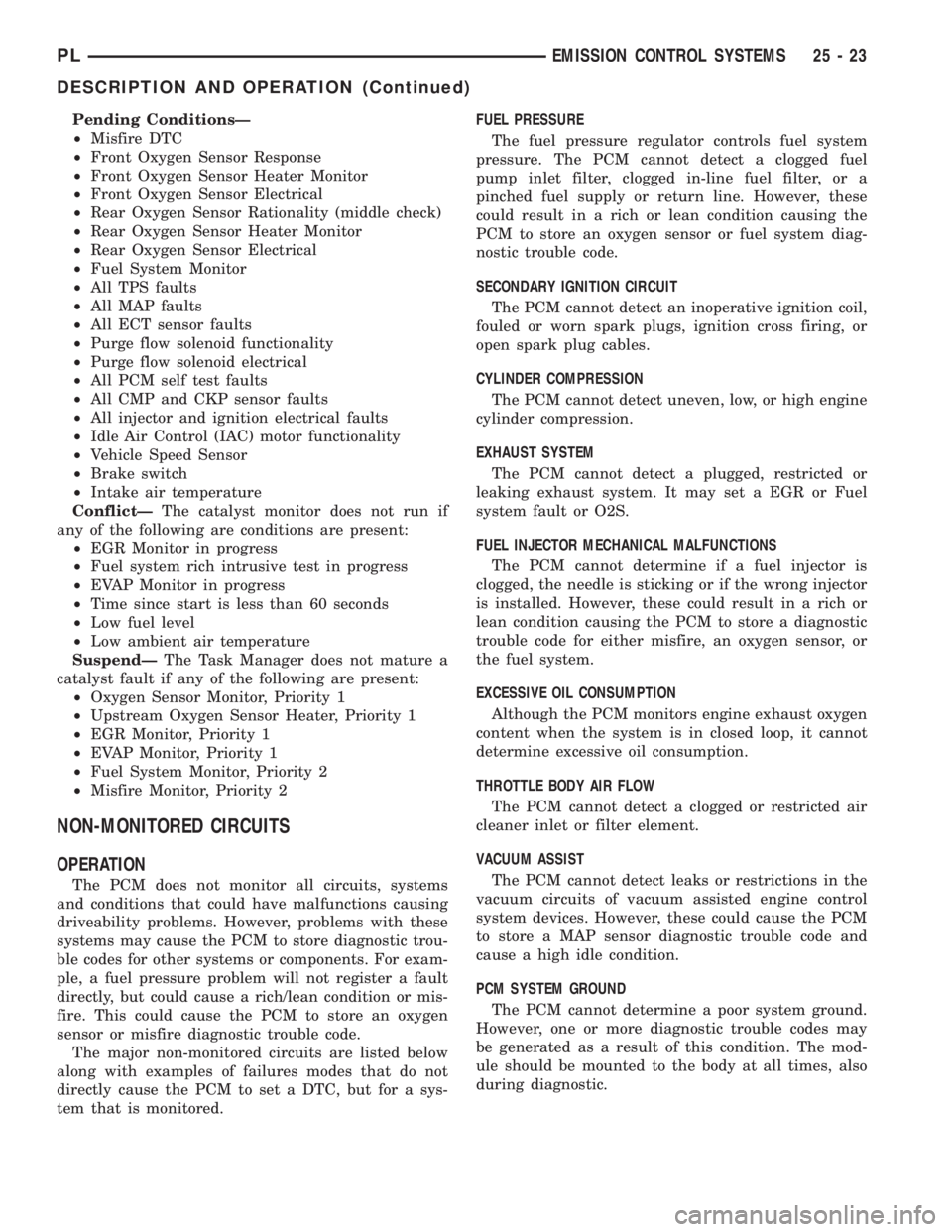
Pending ConditionsÐ
²Misfire DTC
²Front Oxygen Sensor Response
²Front Oxygen Sensor Heater Monitor
²Front Oxygen Sensor Electrical
²Rear Oxygen Sensor Rationality (middle check)
²Rear Oxygen Sensor Heater Monitor
²Rear Oxygen Sensor Electrical
²Fuel System Monitor
²All TPS faults
²All MAP faults
²All ECT sensor faults
²Purge flow solenoid functionality
²Purge flow solenoid electrical
²All PCM self test faults
²All CMP and CKP sensor faults
²All injector and ignition electrical faults
²Idle Air Control (IAC) motor functionality
²Vehicle Speed Sensor
²Brake switch
²Intake air temperature
ConflictÐThe catalyst monitor does not run if
any of the following are conditions are present:
²EGR Monitor in progress
²Fuel system rich intrusive test in progress
²EVAP Monitor in progress
²Time since start is less than 60 seconds
²Low fuel level
²Low ambient air temperature
SuspendÐThe Task Manager does not mature a
catalyst fault if any of the following are present:
²Oxygen Sensor Monitor, Priority 1
²Upstream Oxygen Sensor Heater, Priority 1
²EGR Monitor, Priority 1
²EVAP Monitor, Priority 1
²Fuel System Monitor, Priority 2
²Misfire Monitor, Priority 2
NON-MONITORED CIRCUITS
OPERATION
The PCM does not monitor all circuits, systems
and conditions that could have malfunctions causing
driveability problems. However, problems with these
systems may cause the PCM to store diagnostic trou-
ble codes for other systems or components. For exam-
ple, a fuel pressure problem will not register a fault
directly, but could cause a rich/lean condition or mis-
fire. This could cause the PCM to store an oxygen
sensor or misfire diagnostic trouble code.
The major non-monitored circuits are listed below
along with examples of failures modes that do not
directly cause the PCM to set a DTC, but for a sys-
tem that is monitored.FUEL PRESSURE
The fuel pressure regulator controls fuel system
pressure. The PCM cannot detect a clogged fuel
pump inlet filter, clogged in-line fuel filter, or a
pinched fuel supply or return line. However, these
could result in a rich or lean condition causing the
PCM to store an oxygen sensor or fuel system diag-
nostic trouble code.
SECONDARY IGNITION CIRCUIT
The PCM cannot detect an inoperative ignition coil,
fouled or worn spark plugs, ignition cross firing, or
open spark plug cables.
CYLINDER COMPRESSION
The PCM cannot detect uneven, low, or high engine
cylinder compression.
EXHAUST SYSTEM
The PCM cannot detect a plugged, restricted or
leaking exhaust system. It may set a EGR or Fuel
system fault or O2S.
FUEL INJECTOR MECHANICAL MALFUNCTIONS
The PCM cannot determine if a fuel injector is
clogged, the needle is sticking or if the wrong injector
is installed. However, these could result in a rich or
lean condition causing the PCM to store a diagnostic
trouble code for either misfire, an oxygen sensor, or
the fuel system.
EXCESSIVE OIL CONSUMPTION
Although the PCM monitors engine exhaust oxygen
content when the system is in closed loop, it cannot
determine excessive oil consumption.
THROTTLE BODY AIR FLOW
The PCM cannot detect a clogged or restricted air
cleaner inlet or filter element.
VACUUM ASSIST
The PCM cannot detect leaks or restrictions in the
vacuum circuits of vacuum assisted engine control
system devices. However, these could cause the PCM
to store a MAP sensor diagnostic trouble code and
cause a high idle condition.
PCM SYSTEM GROUND
The PCM cannot determine a poor system ground.
However, one or more diagnostic trouble codes may
be generated as a result of this condition. The mod-
ule should be mounted to the body at all times, also
during diagnostic.
PLEMISSION CONTROL SYSTEMS 25 - 23
DESCRIPTION AND OPERATION (Continued)
Page 1118 of 1285
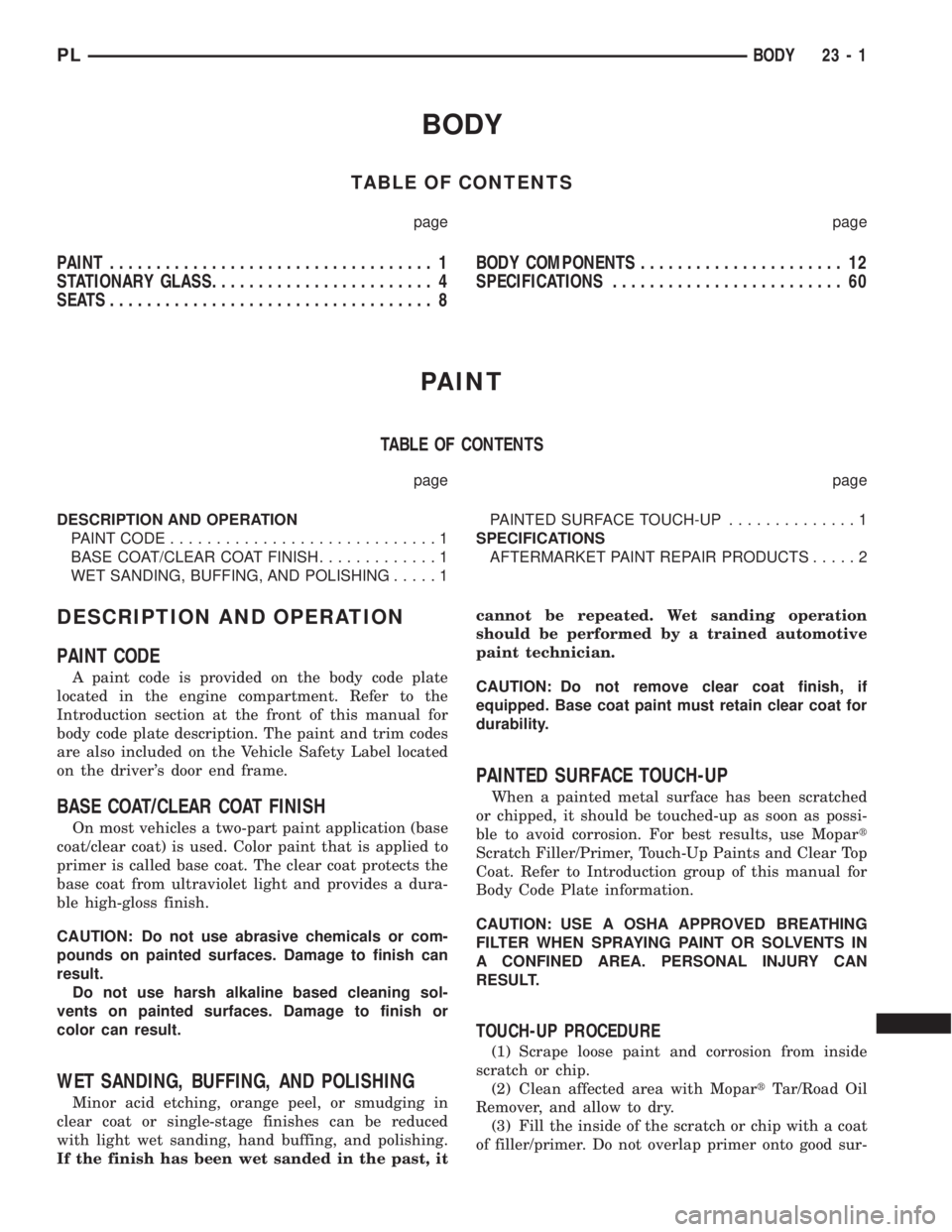
BODY
TABLE OF CONTENTS
page page
PAINT................................... 1
STATIONARY GLASS........................ 4
SEATS ................................... 8BODY COMPONENTS...................... 12
SPECIFICATIONS......................... 60
PAINT
TABLE OF CONTENTS
page page
DESCRIPTION AND OPERATION
PAINT CODE.............................1
BASE COAT/CLEAR COAT FINISH.............1
WET SANDING, BUFFING, AND POLISHING.....1PAINTED SURFACE TOUCH-UP..............1
SPECIFICATIONS
AFTERMARKET PAINT REPAIR PRODUCTS.....2
DESCRIPTION AND OPERATION
PAINT CODE
A paint code is provided on the body code plate
located in the engine compartment. Refer to the
Introduction section at the front of this manual for
body code plate description. The paint and trim codes
are also included on the Vehicle Safety Label located
on the driver's door end frame.
BASE COAT/CLEAR COAT FINISH
On most vehicles a two-part paint application (base
coat/clear coat) is used. Color paint that is applied to
primer is called base coat. The clear coat protects the
base coat from ultraviolet light and provides a dura-
ble high-gloss finish.
CAUTION: Do not use abrasive chemicals or com-
pounds on painted surfaces. Damage to finish can
result.
Do not use harsh alkaline based cleaning sol-
vents on painted surfaces. Damage to finish or
color can result.
WET SANDING, BUFFING, AND POLISHING
Minor acid etching, orange peel, or smudging in
clear coat or single-stage finishes can be reduced
with light wet sanding, hand buffing, and polishing.
If the finish has been wet sanded in the past, itcannot be repeated. Wet sanding operation
should be performed by a trained automotive
paint technician.
CAUTION: Do not remove clear coat finish, if
equipped. Base coat paint must retain clear coat for
durability.
PAINTED SURFACE TOUCH-UP
When a painted metal surface has been scratched
or chipped, it should be touched-up as soon as possi-
ble to avoid corrosion. For best results, use Mopart
Scratch Filler/Primer, Touch-Up Paints and Clear Top
Coat. Refer to Introduction group of this manual for
Body Code Plate information.
CAUTION: USE A OSHA APPROVED BREATHING
FILTER WHEN SPRAYING PAINT OR SOLVENTS IN
A CONFINED AREA. PERSONAL INJURY CAN
RESULT.
TOUCH-UP PROCEDURE
(1) Scrape loose paint and corrosion from inside
scratch or chip.
(2) Clean affected area with MopartTar/Road Oil
Remover, and allow to dry.
(3) Fill the inside of the scratch or chip with a coat
of filler/primer. Do not overlap primer onto good sur-
PLBODY 23 - 1
Page 1232 of 1285
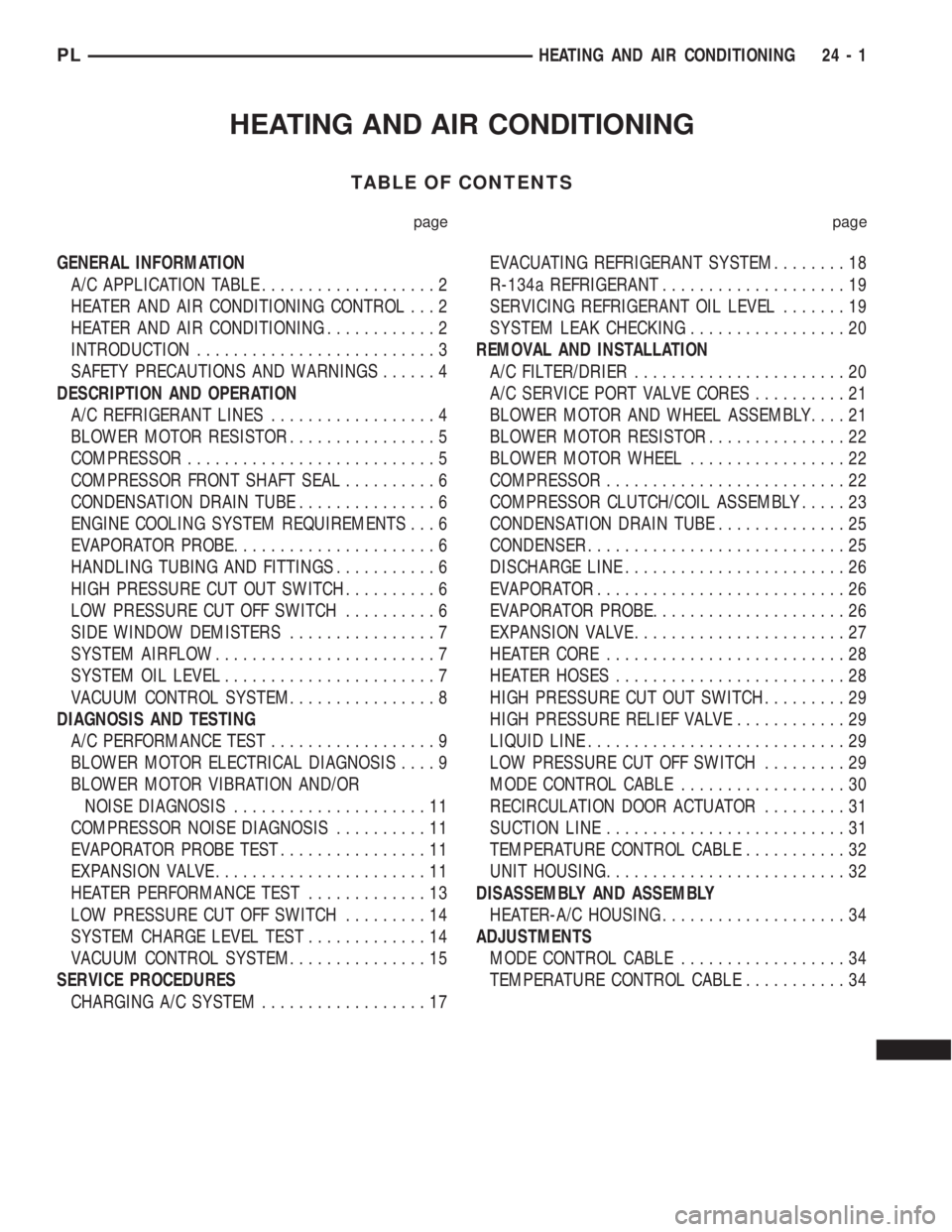
HEATING AND AIR CONDITIONING
TABLE OF CONTENTS
page page
GENERAL INFORMATION
A/C APPLICATION TABLE...................2
HEATER AND AIR CONDITIONING CONTROL...2
HEATER AND AIR CONDITIONING............2
INTRODUCTION..........................3
SAFETY PRECAUTIONS AND WARNINGS......4
DESCRIPTION AND OPERATION
A/C REFRIGERANT LINES..................4
BLOWER MOTOR RESISTOR................5
COMPRESSOR...........................5
COMPRESSOR FRONT SHAFT SEAL..........6
CONDENSATION DRAIN TUBE...............6
ENGINE COOLING SYSTEM REQUIREMENTS...6
EVAPORATOR PROBE......................6
HANDLING TUBING AND FITTINGS...........6
HIGH PRESSURE CUT OUT SWITCH..........6
LOW PRESSURE CUT OFF SWITCH..........6
SIDE WINDOW DEMISTERS................7
SYSTEM AIRFLOW........................7
SYSTEM OIL LEVEL.......................7
VACUUM CONTROL SYSTEM................8
DIAGNOSIS AND TESTING
A/C PERFORMANCE TEST..................9
BLOWER MOTOR ELECTRICAL DIAGNOSIS....9
BLOWER MOTOR VIBRATION AND/OR
NOISE DIAGNOSIS.....................11
COMPRESSOR NOISE DIAGNOSIS..........11
EVAPORATOR PROBE TEST................11
EXPANSION VALVE.......................11
HEATER PERFORMANCE TEST.............13
LOW PRESSURE CUT OFF SWITCH.........14
SYSTEM CHARGE LEVEL TEST.............14
VACUUM CONTROL SYSTEM...............15
SERVICE PROCEDURES
CHARGING A/C SYSTEM..................17EVACUATING REFRIGERANT SYSTEM........18
R-134a REFRIGERANT....................19
SERVICING REFRIGERANT OIL LEVEL.......19
SYSTEM LEAK CHECKING.................20
REMOVAL AND INSTALLATION
A/C FILTER/DRIER.......................20
A/C SERVICE PORT VALVE CORES..........21
BLOWER MOTOR AND WHEEL ASSEMBLY....21
BLOWER MOTOR RESISTOR...............22
BLOWER MOTOR WHEEL.................22
COMPRESSOR..........................22
COMPRESSOR CLUTCH/COIL ASSEMBLY.....23
CONDENSATION DRAIN TUBE..............25
CONDENSER............................25
DISCHARGE LINE........................26
EVAPORATOR...........................26
EVAPORATOR PROBE.....................26
EXPANSION VALVE.......................27
HEATER CORE..........................28
HEATER HOSES.........................28
HIGH PRESSURE CUT OUT SWITCH.........29
HIGH PRESSURE RELIEF VALVE............29
LIQUID LINE............................29
LOW PRESSURE CUT OFF SWITCH.........29
MODE CONTROL CABLE..................30
RECIRCULATION DOOR ACTUATOR.........31
SUCTION LINE..........................31
TEMPERATURE CONTROL CABLE...........32
UNIT HOUSING..........................32
DISASSEMBLY AND ASSEMBLY
HEATER-A/C HOUSING....................34
ADJUSTMENTS
MODE CONTROL CABLE..................34
TEMPERATURE CONTROL CABLE...........34
PLHEATING AND AIR CONDITIONING 24 - 1
Page 1235 of 1285
SAFETY PRECAUTIONS AND WARNINGS
WARNING: WEAR EYE PROTECTION WHEN SER-
VICING THE AIR CONDITIONING REFRIGERANT
SYSTEM. SERIOUS EYE INJURY CAN RESULT
FROM EYE CONTACT WITH REFRIGERANT. IF EYE
CONTACT IS MADE, SEEK MEDICAL ATTENTION
IMMEDIATELY.
DO NOT EXPOSE REFRIGERANT TO OPEN
FLAME. POISONOUS GAS IS CREATED WHEN
REFRIGERANT IS BURNED. AN ELECTRONIC TYPE
LEAK DETECTOR IS RECOMMENDED.
LARGE AMOUNTS OF REFRIGERANT RELEASED
IN A CLOSED WORK AREA WILL DISPLACE THE
OXYGEN AND CAUSE SUFFOCATION.
THE EVAPORATION RATE OF REFRIGERANT AT
AVERAGE TEMPERATURE AND ALTITUDE IS
EXTREMELY HIGH. AS A RESULT, ANYTHING THAT
COMES IN CONTACT WITH THE REFRIGERANT
WILL FREEZE. ALWAYS PROTECT SKIN OR DELI-
CATE OBJECTS FROM DIRECT CONTACT WITH
REFRIGERANT. R-134a SERVICE EQUIPMENT OR
VEHICLE A/C SYSTEM SHOULD NOT BE PRES-
SURE TESTED OR LEAK TESTED WITH COM-
PRESSED AIR.
SOME MIXTURES OF AIR and R-134a HAVE BEEN
SHOWN TO BE COMBUSTIBLE AT ELEVATED
PRESSURES. THESE MIXTURES ARE POTENTIALLY
DANGEROUS AND MAY RESULT IN FIRE OR
EXPLOSION CAUSING INJURY OR PROPERTY
DAMAGE.
ANTIFREEZE IS AN ETHYLENE GLYCOL BASE
COOLANT AND IS HARMFUL IF SWALLOWED OR
INHALED. SEEK MEDICAL ATTENTION IMMEDI-
ATELY IF SWALLOWED OR INHALED. DO NOT
STORE IN OPEN OR UNMARKED CONTAINERS.
WASH SKIN AND CLOTHING THOROUGHLY AFTER
COMING IN CONTACT WITH ETHYLENE GLYCOL.
KEEP OUT OF REACH OF CHILDREN AND PETS.
DO NOT OPEN A COOLING SYSTEM WHEN THE
ENGINE IS AT RUNNING TEMPERATURE. PER-
SONAL INJURY CAN RESULT.
CAUTION: The engine cooling system is designed
to develop internal pressure of 97 to 123 kPa (14 to
18 psi). Allow the vehicle to cool a minimum of 15
minutes before opening the cooling system. Refer
to Group 7, Cooling System.
DESCRIPTION AND OPERATION
A/C REFRIGERANT LINES
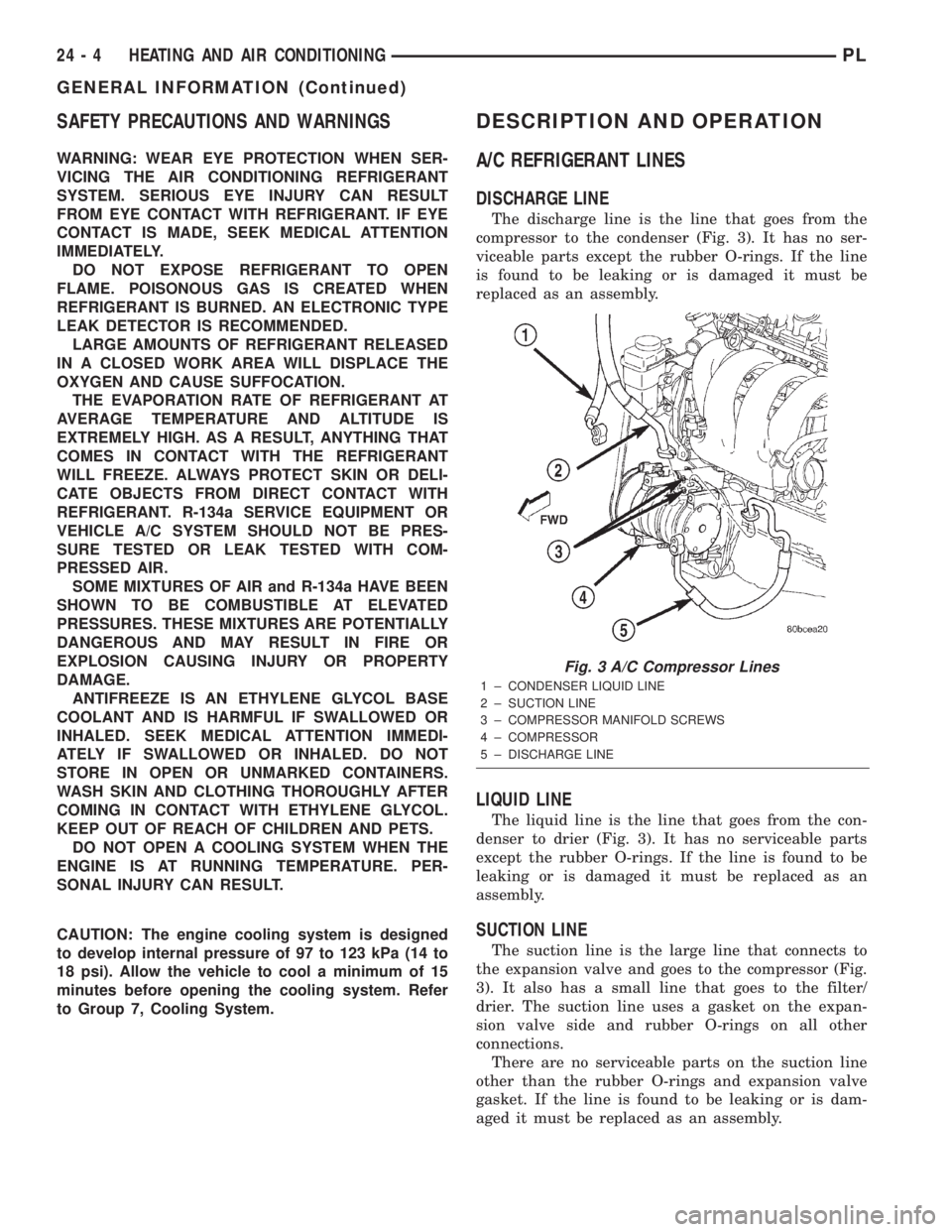
DISCHARGE LINE
The discharge line is the line that goes from the
compressor to the condenser (Fig. 3). It has no ser-
viceable parts except the rubber O-rings. If the line
is found to be leaking or is damaged it must be
replaced as an assembly.
LIQUID LINE
The liquid line is the line that goes from the con-
denser to drier (Fig. 3). It has no serviceable parts
except the rubber O-rings. If the line is found to be
leaking or is damaged it must be replaced as an
assembly.
SUCTION LINE
The suction line is the large line that connects to
the expansion valve and goes to the compressor (Fig.
3). It also has a small line that goes to the filter/
drier. The suction line uses a gasket on the expan-
sion valve side and rubber O-rings on all other
connections.
There are no serviceable parts on the suction line
other than the rubber O-rings and expansion valve
gasket. If the line is found to be leaking or is dam-
aged it must be replaced as an assembly.
Fig. 3 A/C Compressor Lines
1 ± CONDENSER LIQUID LINE
2 ± SUCTION LINE
3 ± COMPRESSOR MANIFOLD SCREWS
4 ± COMPRESSOR
5 ± DISCHARGE LINE
24 - 4 HEATING AND AIR CONDITIONINGPL
GENERAL INFORMATION (Continued)
Page 1236 of 1285
A/C SERVICE PORT VALVE CORES
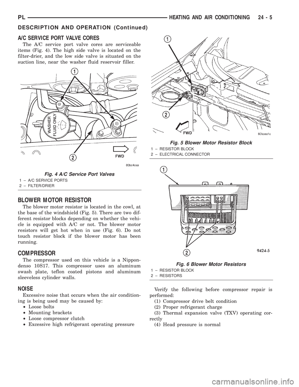
The A/C service port valve cores are serviceable
items (Fig. 4). The high side valve is located on the
filter-drier, and the low side valve is situated on the
suction line, near the washer fluid reservoir filler.
BLOWER MOTOR RESISTOR
The blower motor resistor is located in the cowl, at
the base of the windshield (Fig. 5). There are two dif-
ferent resistor blocks depending on whether the vehi-
cle is equipped with A/C or not. The blower motor
resistors will get hot when in use (Fig. 6). Do not
touch resistor block if the blower motor has been
running.
COMPRESSOR
The compressor used on this vehicle is a Nippon-
denso 10S17. This compressor uses an aluminum
swash plate, teflon coated pistons and aluminum
sleeveless cylinder walls.
NOISE
Excessive noise that occurs when the air condition-
ing is being used may be caused by:
²Loose bolts
²Mounting brackets
²Loose compressor clutch
²Excessive high refrigerant operating pressureVerify the following before compressor repair is
performed:
(1) Compressor drive belt condition
(2) Proper refrigerant charge
(3) Thermal expansion valve (TXV) operating cor-
rectly
(4) Head pressure is normal
Fig. 4 A/C Service Port Valves
1 ± A/C SERVICE PORTS
2 ± FILTER/DRIER
Fig. 5 Blower Motor Resistor Block
1 ± RESISTOR BLOCK
2 ± ELECTRICAL CONNECTOR
Fig. 6 Blower Motor Resistors
1 ± RESISTOR BLOCK
2 ± RESISTORS
PLHEATING AND AIR CONDITIONING 24 - 5
DESCRIPTION AND OPERATION (Continued)
Page 1239 of 1285
NOTE: The oil used in the compressor is ND8 PAG
R-134a refrigerant oil. Only refrigerant oil of the
same type should be used to service the system.
Do not use any other oil. The oil container should
be kept tightly capped until it is ready for use.
Tightly cap afterwards to prevent contamination
from dirt and moisture. Refrigerant oil will quickly
absorb any moisture it comes in contact with. Spe-
cial effort must be used to keep all R-134a system
components moisture-free. Moisture in the oil is
very difficult to remove and will cause a reliability
problem with the compressor.
It will not be necessary to check oil level in the
compressor or to add oil unless there has been an oil
loss. Oil loss at a leak point will be evident by the
presence of a wet, shiny surface around the leak.
REFRIGERANT OIL LEVEL CHECK
When an air conditioning system is first assem-
bled, all components (except the compressor) are
refrigerant oil free. After the system has been
charged with R-134a refrigerant and operated, the oil
in the compressor is dispersed through the lines and
components. The evaporator, condenser, and filter-
drier will retain a significant amount of oil, refer to
the Refrigerant Oil Capacities chart. When a compo-
nent is replaced, the specified amount of refrigerant
oil must be added. When the compressor is replaced,
the amount of oil that is retained in the rest of the
system must be drained from the replacement com-
pressor. When a line or component has ruptured and
oil has escaped, the compressor should be removed
and drained. The filter-drier must be replaced along
with the ruptured part. The oil capacity of the sys-
tem, minus the amount of oil still in the remaining
components, can be measured and poured into the
suction port of the compressor.
VACUUM CONTROL SYSTEM
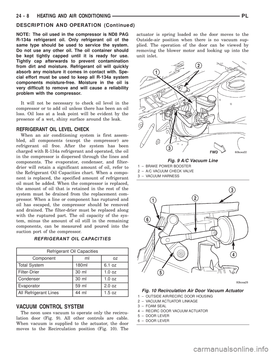
The neon uses vacuum to operate only the recircu-
lation door (Fig. 9). All other controls are cable.
When vacuum is supplied to the actuator, the door
moves to the Recirculation position (Fig. 10). Theactuator is spring loaded so the door moves to the
Outside-air position when there is no vacuum sup-
plied. The operation of the door can be viewed by
removing the blower motor and looking up into the
unit inlet.
REFRIGERANT OIL CAPACITIES
Refrigerant Oil Capacities
Component ml oz
Total System 180ml 6.1 oz
Filter-Drier 30 ml 1.0 oz
Condenser 30 ml 1.0 oz
Evaporator 59 ml 2.0 oz
All Refrigerant Lines 44 ml 1.5 oz
Fig. 9 A/C Vacuum Line
1 ± BRAKE POWER BOOSTER
2 ± A/C VACUUM CHECK VALVE
3 ± VACUUM HARNESS
Fig. 10 Recirculation Air Door Vacuum Actuator
1 ± OUTSIDE AIR/RECIRC DOOR HOUSING
2 ± VACUUM ACTUATOR LINKAGE
3 ± FOAM SEAL
4 ± RECIRC DOOR VACUUM ACTUATOR
5 ± DOOR LEVER
6 ± DOOR LEVER
24 - 8 HEATING AND AIR CONDITIONINGPL
DESCRIPTION AND OPERATION (Continued)
Page 1240 of 1285
Normally, vacuum is supplied to the actuator by
placing the Circulation control knob in the Recircula-
tion position. The Mode and the circulation control
are mechanically interlocked so the circulation con-
trol cannot be placed in the RECIRC position if the
mode control is at or between the mix and defrost
positions. Vacuum is supplied to the actuator only
when circulation control is at the RECIRC position.
If the circulation control is between the outside air
position and RECIRC position the system will be in
outside air. If the circulation control is in the
RECIRC position and the mode control is moved from
the floor to the defrost positions, the circulation con-
trol will move from the RECIRC position, to the out-
side air position beginning at the mix position. This
is to prevent window fogging.
DIAGNOSIS AND TESTING
A/C PERFORMANCE TEST
The air conditioning system is designed to remove
heat and humidity from the air entering the passen-
ger compartment. The evaporator, located in the
heater A/C unit, is cooled to temperatures near the
freezing point. As warm damp air passes over the
fins in the evaporator, moisture in the air condenses
to water, dehumidifying the air. Condensation on the
evaporator fins reduces the evaporators ability to
absorb heat. During periods of high heat and humid-
ity, an air conditioning system will be less effective.
With the instrument control set to RECIRC, only air
from the passenger compartment passes through theevaporator. As the passenger compartment air dehu-
midifies, A/C performance levels rise.
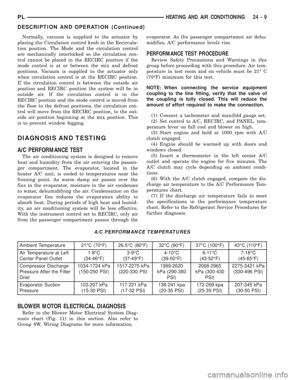
PERFORMANCE TEST PROCEDURE
Review Safety Precautions and Warnings in this
group before proceeding with this procedure. Air tem-
perature in test room and on vehicle must be 21É C
(70ÉF) minimum for this test.
NOTE: When connecting the service equipment
coupling to the line fitting, verify that the valve of
the coupling is fully closed. This will reduce the
amount of effort required to make the connection.
(1) Connect a tachometer and manifold gauge set.
(2) Set control to A/C, RECIRC, and PANEL, tem-
perature lever on full cool and blower on high.
(3) Start engine and hold at 1000 rpm with A/C
clutch engaged.
(4) Engine should be warmed up with doors and
windows closed.
(5) Insert a thermometer in the left center A/C
outlet and operate the engine for five minutes. The
A/C clutch may cycle depending on ambient condi-
tions.
(6) With the A/C clutch engaged, compare the dis-
charge air temperature to the A/C Performance Tem-
peratures chart.
(7) If the discharge air temperature fails to meet
the specifications in the performance temperature
chart. Refer to the Refrigerant Service Procedures for
further diagnosis.
A/C PERFORMANCE TEMPERATURES
Ambient Temperature 21ÉC (70ÉF) 26.5ÉC (80ÉF) 32ÉC (90ÉF) 37ÉC (100ÉF) 43ÉC (110ÉF)
Air Temperature at Left
Center Panel Outlet1-8ÉC
(34-46ÉF)3-9ÉC
(37-49ÉF)4-10ÉC
(39-50ÉF)6-11ÉC
(43-52ÉF)7-18ÉC
(45-65ÉF)
Compressor Discharge
Pressure After the Filter
Drier1034-1724 kPa
(150-250 PSI)1517-2275 kPa
(220-330 PSI1999-2620
kPa (290-380
PSI)2068-2965
kPa (300-430
PSI)2275-3421 kPa
(330-496 PSI)
Evaporator Suction
Pressure103-207 kPa
(15-30 PSI)117-221 kPa
(17-32 PSI)138-241 kpa
(20-35 PSI)172-269 kpa
(25-39 PSI)207-345 kPa
(30-50 PSI)
BLOWER MOTOR ELECTRICAL DIAGNOSIS
Refer to the Blower Motor Electrical System Diag-
nosis chart (Fig. 11) in this section. Also refer to
Group 8W, Wiring Diagrams for more information.
PLHEATING AND AIR CONDITIONING 24 - 9
DESCRIPTION AND OPERATION (Continued)