2000 DODGE NEON brake sensor
[x] Cancel search: brake sensorPage 164 of 1285
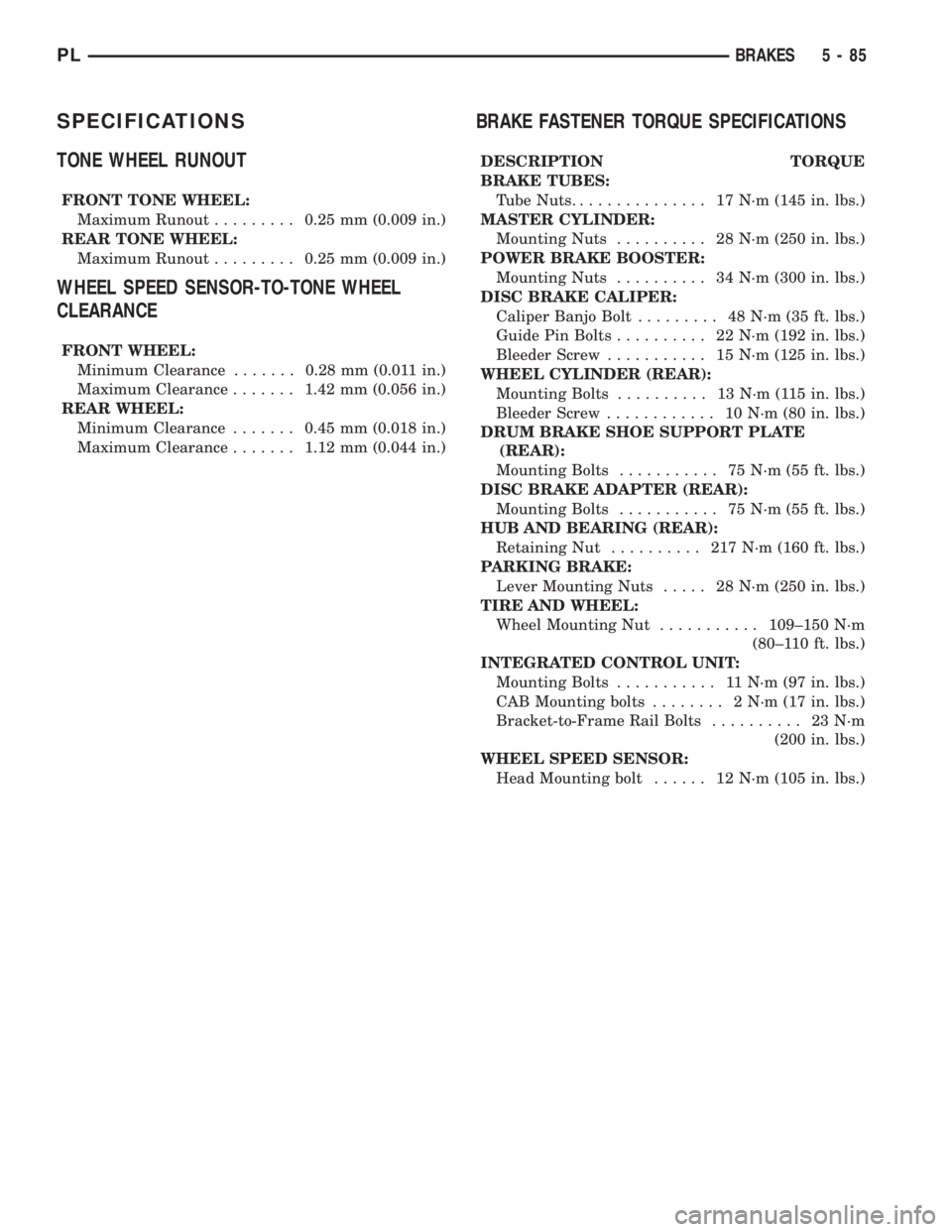
SPECIFICATIONS
TONE WHEEL RUNOUT
FRONT TONE WHEEL:
Maximum Runout.........0.25 mm (0.009 in.)
REAR TONE WHEEL:
Maximum Runout.........0.25 mm (0.009 in.)
WHEEL SPEED SENSOR-TO-TONE WHEEL
CLEARANCE
FRONT WHEEL:
Minimum Clearance.......0.28 mm (0.011 in.)
Maximum Clearance.......1.42 mm (0.056 in.)
REAR WHEEL:
Minimum Clearance.......0.45 mm (0.018 in.)
Maximum Clearance.......1.12 mm (0.044 in.)
BRAKE FASTENER TORQUE SPECIFICATIONS
DESCRIPTION TORQUE
BRAKE TUBES:
Tube Nuts............... 17N´m(145 in. lbs.)
MASTER CYLINDER:
Mounting Nuts.......... 28N´m(250 in. lbs.)
POWER BRAKE BOOSTER:
Mounting Nuts.......... 34N´m(300 in. lbs.)
DISC BRAKE CALIPER:
Caliper Banjo Bolt......... 48N´m(35ft.lbs.)
Guide Pin Bolts.......... 22N´m(192 in. lbs.)
Bleeder Screw........... 15N´m(125 in. lbs.)
WHEEL CYLINDER (REAR):
Mounting Bolts.......... 13N´m(115in.lbs.)
Bleeder Screw............ 10N´m(80in.lbs.)
DRUM BRAKE SHOE SUPPORT PLATE
(REAR):
Mounting Bolts........... 75N´m(55ft.lbs.)
DISC BRAKE ADAPTER (REAR):
Mounting Bolts........... 75N´m(55ft.lbs.)
HUB AND BEARING (REAR):
Retaining Nut.......... 217N´m(160 ft. lbs.)
PARKING BRAKE:
Lever Mounting Nuts..... 28N´m(250 in. lbs.)
TIRE AND WHEEL:
Wheel Mounting Nut...........109±150 N´m
(80±110 ft. lbs.)
INTEGRATED CONTROL UNIT:
Mounting Bolts........... 11N´m(97in.lbs.)
CAB Mounting bolts........ 2N´m(17in.lbs.)
Bracket-to-Frame Rail Bolts.......... 23N´m
(200 in. lbs.)
WHEEL SPEED SENSOR:
Head Mounting bolt...... 12N´m(105 in. lbs.)
PLBRAKES 5 - 85
Page 173 of 1285
housing does not move, it is improperly installed or
defective.
(3) Route cable to the transaxle and connect cable
end to the clutch release lever and transaxle housing
(Fig. 7).
(4) Install bellhousing cap (Fig. 7).
(5) Install and fasten battery tray.
(6) Install battery and hold-down clamp.
(7) Connect both battery cables.
(8) Verify that the clutch cable is working properly.
CLUTCH INTERLOCK/UPSTOP SWITCH
REMOVAL
(1) Disconnect and isolate battery negative cable.
(2) Remove instrument panel assembly. Refer to
Group 8E, Instrument Panel and Systems for the
proper procedure.
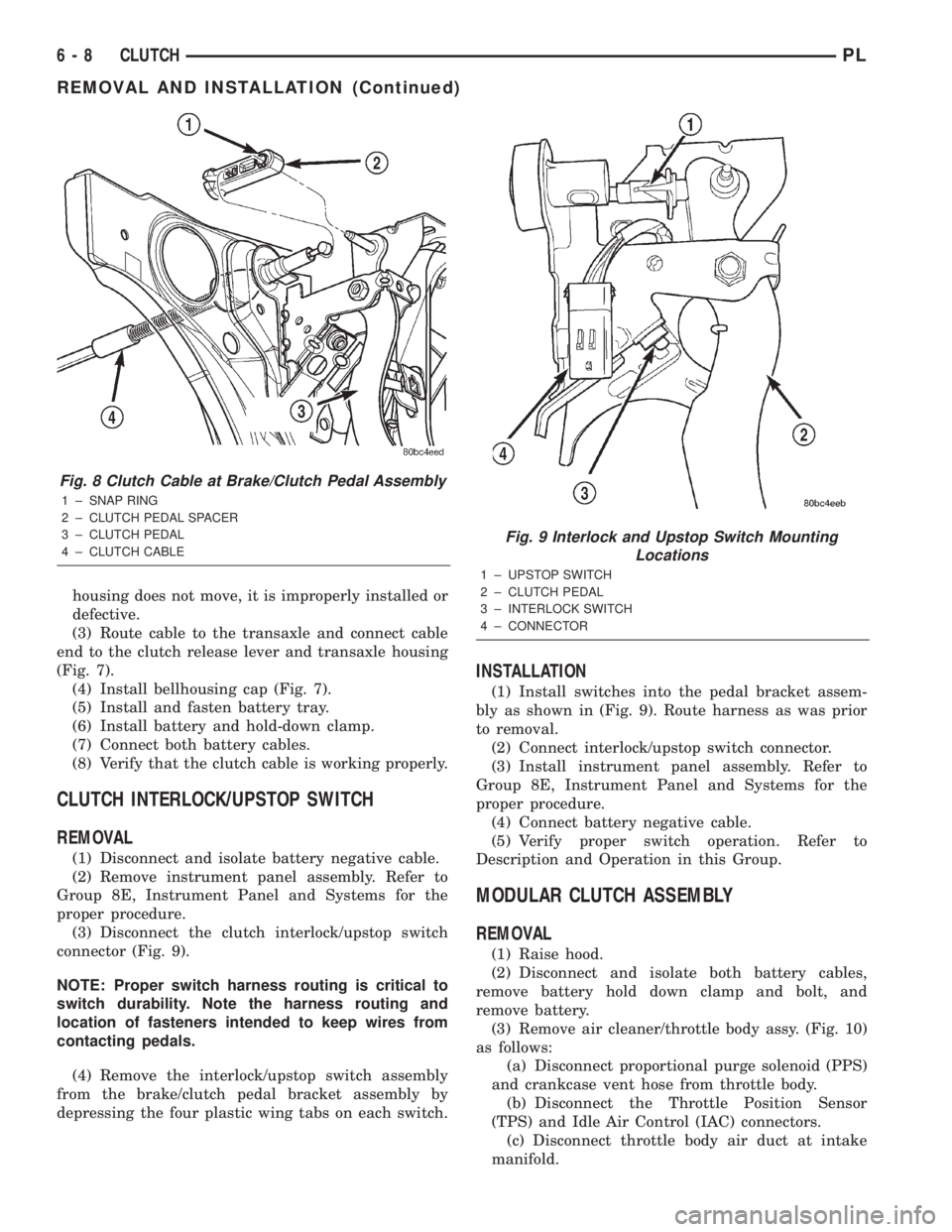
(3) Disconnect the clutch interlock/upstop switch
connector (Fig. 9).
NOTE: Proper switch harness routing is critical to
switch durability. Note the harness routing and
location of fasteners intended to keep wires from
contacting pedals.
(4) Remove the interlock/upstop switch assembly
from the brake/clutch pedal bracket assembly by
depressing the four plastic wing tabs on each switch.
INSTALLATION
(1) Install switches into the pedal bracket assem-
bly as shown in (Fig. 9). Route harness as was prior
to removal.
(2) Connect interlock/upstop switch connector.
(3) Install instrument panel assembly. Refer to
Group 8E, Instrument Panel and Systems for the
proper procedure.
(4) Connect battery negative cable.
(5) Verify proper switch operation. Refer to
Description and Operation in this Group.
MODULAR CLUTCH ASSEMBLY
REMOVAL
(1) Raise hood.
(2) Disconnect and isolate both battery cables,
remove battery hold down clamp and bolt, and
remove battery.
(3) Remove air cleaner/throttle body assy. (Fig. 10)
as follows:
(a) Disconnect proportional purge solenoid (PPS)
and crankcase vent hose from throttle body.
(b) Disconnect the Throttle Position Sensor
(TPS) and Idle Air Control (IAC) connectors.
(c) Disconnect throttle body air duct at intake
manifold.
Fig. 8 Clutch Cable at Brake/Clutch Pedal Assembly
1 ± SNAP RING
2 ± CLUTCH PEDAL SPACER
3 ± CLUTCH PEDAL
4 ± CLUTCH CABLE
Fig. 9 Interlock and Upstop Switch Mounting
Locations
1 ± UPSTOP SWITCH
2 ± CLUTCH PEDAL
3 ± INTERLOCK SWITCH
4 ± CONNECTOR
6 - 8 CLUTCHPL
REMOVAL AND INSTALLATION (Continued)
Page 242 of 1285
REMOVAL
(1) Remove brake booster hose and electrical con-
nector from holders on end of cylinder head cover
and reposition.
(2) Disconnect electrical connectors from camshaft
position sensor.
(3) Remove camshaft position sensor mounting
screws. Remove sensor.
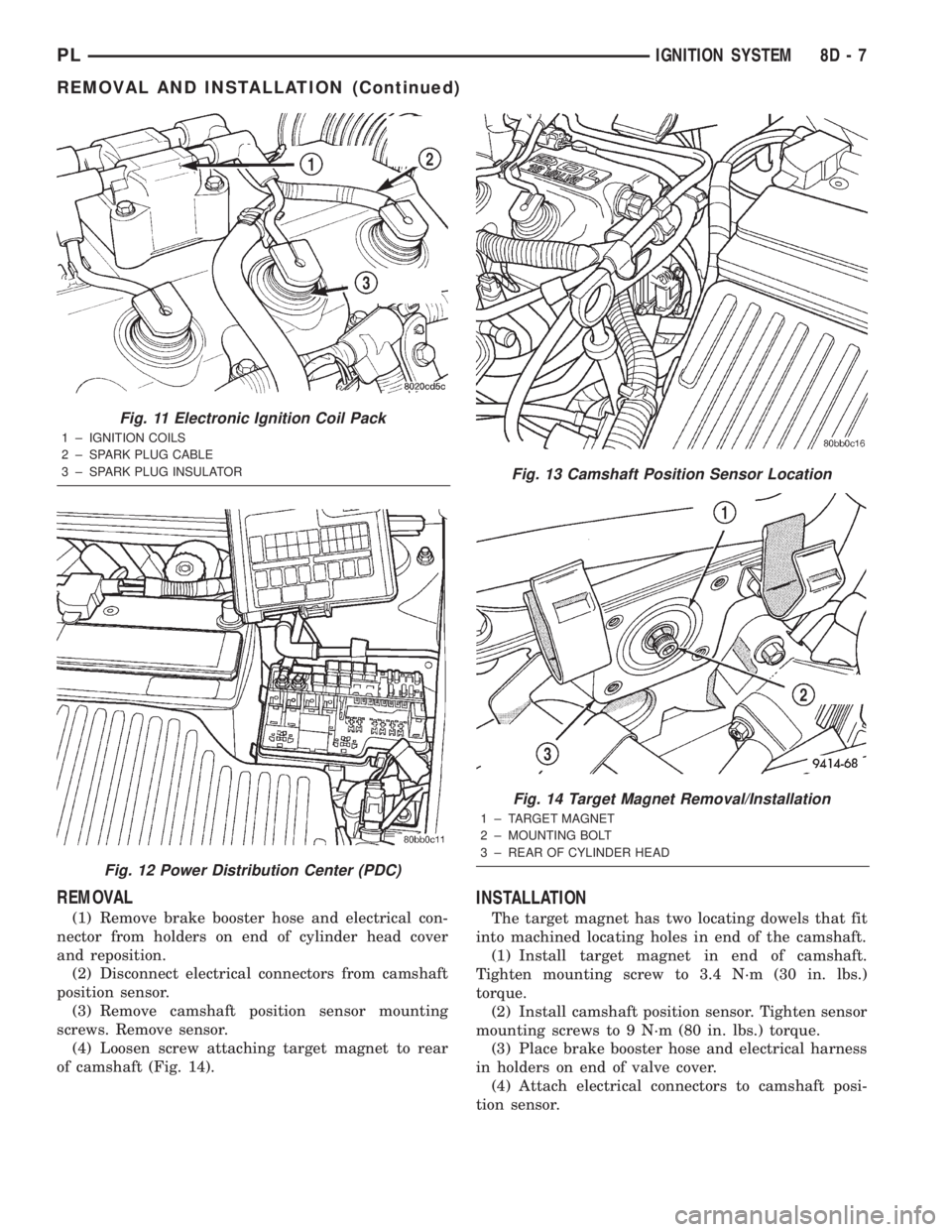
(4) Loosen screw attaching target magnet to rear
of camshaft (Fig. 14).
INSTALLATION
The target magnet has two locating dowels that fit
into machined locating holes in end of the camshaft.
(1) Install target magnet in end of camshaft.
Tighten mounting screw to 3.4 N´m (30 in. lbs.)
torque.
(2) Install camshaft position sensor. Tighten sensor
mounting screws to 9 N´m (80 in. lbs.) torque.
(3) Place brake booster hose and electrical harness
in holders on end of valve cover.
(4) Attach electrical connectors to camshaft posi-
tion sensor.
Fig. 11 Electronic Ignition Coil Pack
1 ± IGNITION COILS
2 ± SPARK PLUG CABLE
3 ± SPARK PLUG INSULATOR
Fig. 12 Power Distribution Center (PDC)
Fig. 13 Camshaft Position Sensor Location
Fig. 14 Target Magnet Removal/Installation
1 ± TARGET MAGNET
2 ± MOUNTING BOLT
3 ± REAR OF CYLINDER HEAD
PLIGNITION SYSTEM 8D - 7
REMOVAL AND INSTALLATION (Continued)
Page 248 of 1285
INSTRUMENT PANEL SYSTEMS
TABLE OF CONTENTS
page page
GENERAL INFORMATION
INTRODUCTION..........................1
DESCRIPTION AND OPERATION
HEADLAMP SWITCH......................2
INSTRUMENT CLUSTER....................2
WARNING AND INDICATOR LAMPS..........2
DIAGNOSIS AND TESTING
AIRBAG WARNING SYSTEM................2
BRAKE SYSTEM WARNING LAMP TEST.......2
INSTRUMENT CLUSTER LAMPS.............2
LOW OIL PRESSURE WARNING LAMP TEST...3
MULTIPLE/INDIVIDUAL GAUGES
INOPERATIVE..........................4
SERVICE PROCEDURES
INSTRUMENT CLUSTER SELF-DIAGNOSTICS...4
REMOVAL AND INSTALLATION
ACCESSORY SWITCH/POWER OUTLET
BEZEL................................4CENTER CONSOLE FLOOD LAMP............5
CIGAR LIGHTER / POWER OUTLET
ASSEMBLY.............................5
GLOVE BOX DOOR/BIN....................6
GLOVE BOX DOOR/BIN....................6
GLOVE BOX SWITCH/LAMP.................6
INSTRUMENT CLUSTER....................6
INSTRUMENT CLUSTER BEZEL..............6
INSTRUMENT CLUSTER LAMPS.............7
INSTRUMENT PANEL ASSEMBLY............7
INSTRUMENT PANEL CENTER BEZEL........10
INSTRUMENT PANEL END CAPS............10
INSTRUMENT PANEL TOP COVER...........10
LOWER INSTRUMENT PANEL COVER........10
LOWER STORAGE BIN....................10
STEERING COLUMN SHROUDS.............11
GENERAL INFORMATION
INTRODUCTION
The purpose of the dash gauges and indicator
lamps is to keep the driver informed about the oper-
ating condition of the vehicle. If an abnormal condi-
tion occurs, the driver is informed by indicator lamp.
The driver can seek service before damage occurs.
Indicator lamps use ON/OFF switch functions for
operation, while gauges use a sending unit or sensor.
The Instrument Panel can be removed as an
assembly after a few part are removed to allow
access to the retaining bolts. There is one self-align-
ing bulkhead connector on the left underside of the
instrument panel replacing most of the main harness
connectors. Once removed, the instrument panel can
be serviced for replacement. Most of the parts of the
instrument panel can be replaced individually with-
out removing the complete instrument panel assem-
bly.
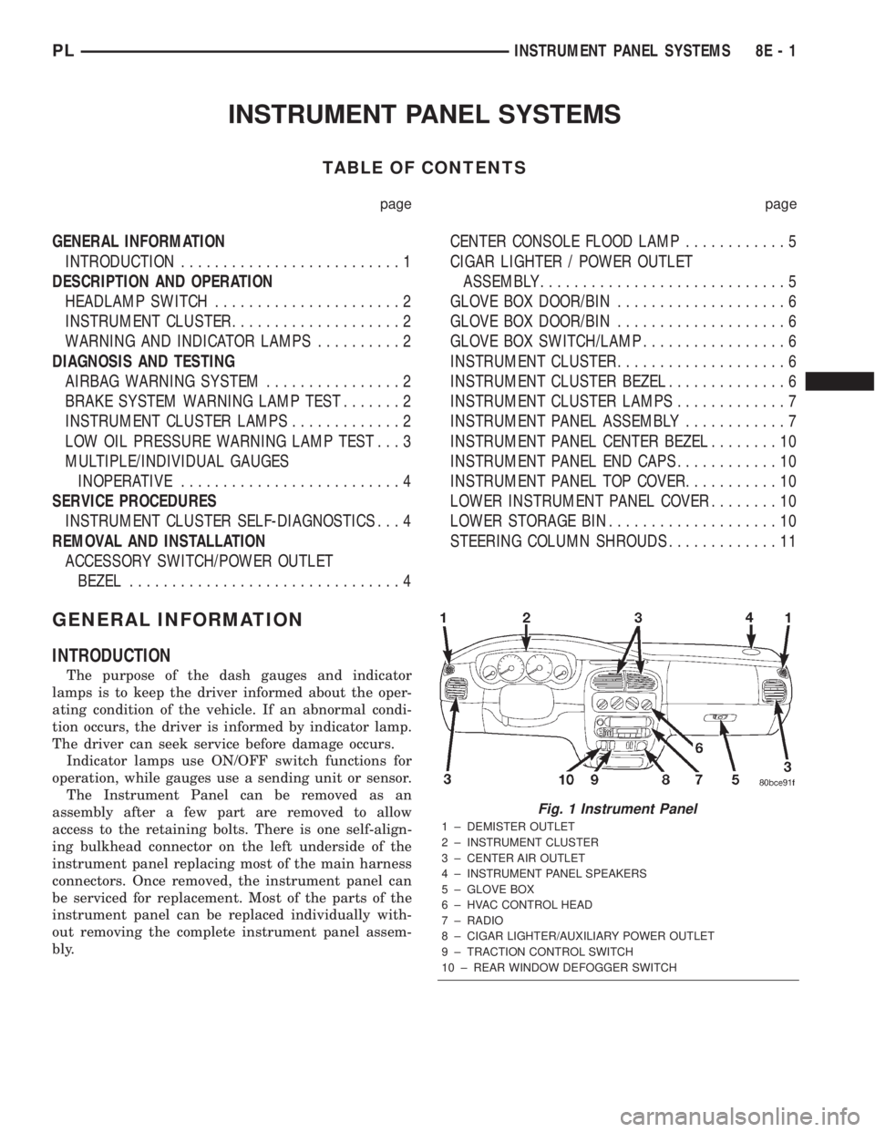
Fig. 1 Instrument Panel
1 ± DEMISTER OUTLET
2 ± INSTRUMENT CLUSTER
3 ± CENTER AIR OUTLET
4 ± INSTRUMENT PANEL SPEAKERS
5 ± GLOVE BOX
6 ± HVAC CONTROL HEAD
7 ± RADIO
8 ± CIGAR LIGHTER/AUXILIARY POWER OUTLET
9 ± TRACTION CONTROL SWITCH
10 ± REAR WINDOW DEFOGGER SWITCH
PLINSTRUMENT PANEL SYSTEMS 8E - 1
Page 251 of 1285
MULTIPLE/INDIVIDUAL GAUGES INOPERATIVE
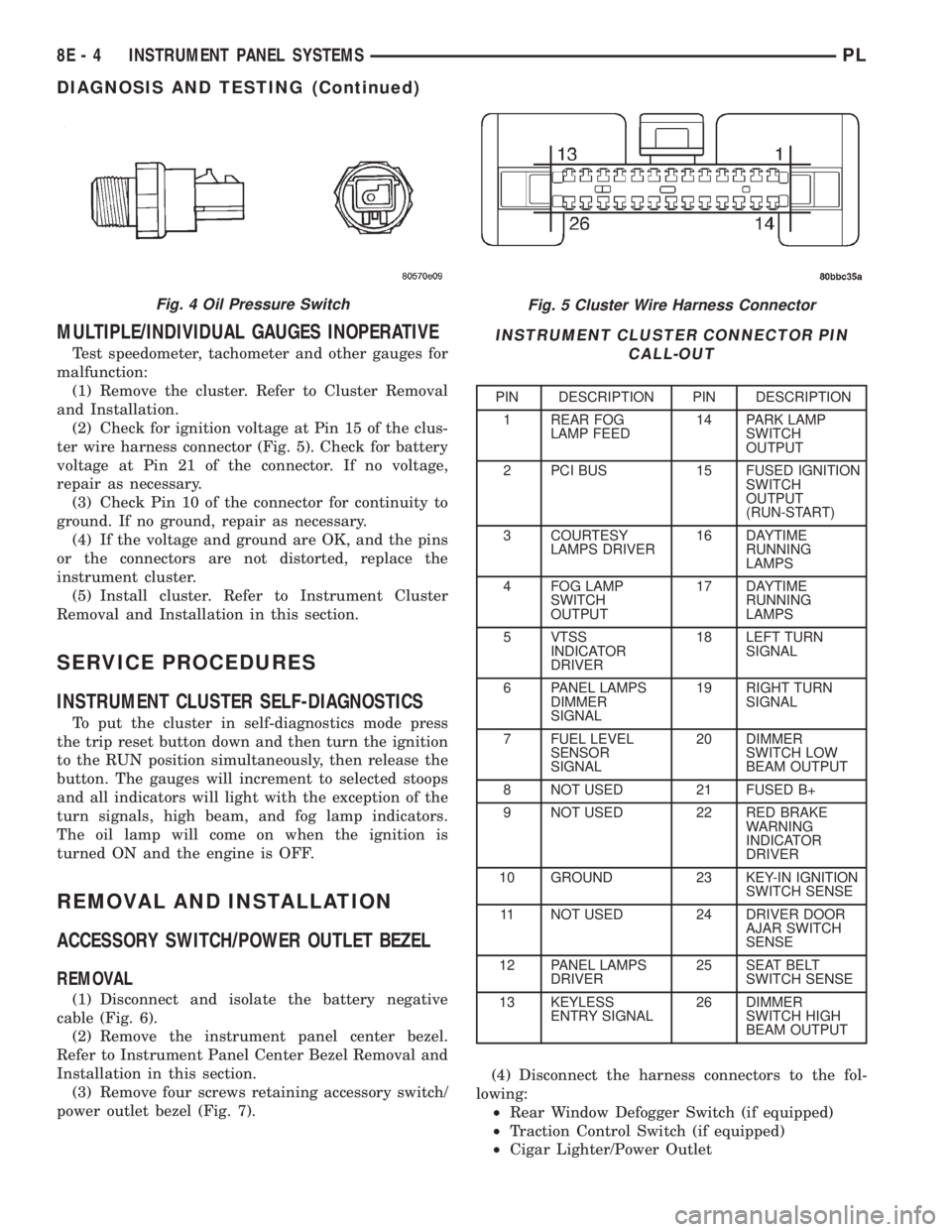
Test speedometer, tachometer and other gauges for
malfunction:
(1) Remove the cluster. Refer to Cluster Removal
and Installation.
(2) Check for ignition voltage at Pin 15 of the clus-
ter wire harness connector (Fig. 5). Check for battery
voltage at Pin 21 of the connector. If no voltage,
repair as necessary.
(3) Check Pin 10 of the connector for continuity to
ground. If no ground, repair as necessary.
(4) If the voltage and ground are OK, and the pins
or the connectors are not distorted, replace the
instrument cluster.
(5) Install cluster. Refer to Instrument Cluster
Removal and Installation in this section.
SERVICE PROCEDURES
INSTRUMENT CLUSTER SELF-DIAGNOSTICS
To put the cluster in self-diagnostics mode press
the trip reset button down and then turn the ignition
to the RUN position simultaneously, then release the
button. The gauges will increment to selected stoops
and all indicators will light with the exception of the
turn signals, high beam, and fog lamp indicators.
The oil lamp will come on when the ignition is
turned ON and the engine is OFF.
REMOVAL AND INSTALLATION
ACCESSORY SWITCH/POWER OUTLET BEZEL
REMOVAL
(1) Disconnect and isolate the battery negative
cable (Fig. 6).
(2) Remove the instrument panel center bezel.
Refer to Instrument Panel Center Bezel Removal and
Installation in this section.
(3) Remove four screws retaining accessory switch/
power outlet bezel (Fig. 7).(4) Disconnect the harness connectors to the fol-
lowing:
²Rear Window Defogger Switch (if equipped)
²Traction Control Switch (if equipped)
²Cigar Lighter/Power Outlet
Fig. 5 Cluster Wire Harness Connector
INSTRUMENT CLUSTER CONNECTOR PIN
CALL-OUT
PIN DESCRIPTION PIN DESCRIPTION
1 REAR FOG
LAMP FEED14 PARK LAMP
SWITCH
OUTPUT
2 PCI BUS 15 FUSED IGNITION
SWITCH
OUTPUT
(RUN-START)
3 COURTESY
LAMPS DRIVER16 DAYTIME
RUNNING
LAMPS
4 FOG LAMP
SWITCH
OUTPUT17 DAYTIME
RUNNING
LAMPS
5 VTSS
INDICATOR
DRIVER18 LEFT TURN
SIGNAL
6 PANEL LAMPS
DIMMER
SIGNAL19 RIGHT TURN
SIGNAL
7 FUEL LEVEL
SENSOR
SIGNAL20 DIMMER
SWITCH LOW
BEAM OUTPUT
8 NOT USED 21 FUSED B+
9 NOT USED 22 RED BRAKE
WARNING
INDICATOR
DRIVER
10 GROUND 23 KEY-IN IGNITION
SWITCH SENSE
11 NOT USED 24 DRIVER DOOR
AJAR SWITCH
SENSE
12 PANEL LAMPS
DRIVER25 SEAT BELT
SWITCH SENSE
13 KEYLESS
ENTRY SIGNAL26 DIMMER
SWITCH HIGH
BEAM OUTPUT
Fig. 4 Oil Pressure Switch
8E - 4 INSTRUMENT PANEL SYSTEMSPL
DIAGNOSIS AND TESTING (Continued)
Page 286 of 1285
VEHICLE SPEED CONTROL SYSTEM
TABLE OF CONTENTS
page page
DESCRIPTION AND OPERATION
SPEED CONTROL SYSTEM.................1
SPEED CONTROL SERVO-PCM OUTPUT.......2
SPEED CONTROL SWITCHESÐPCM INPUT....2
STOP LAMP SWITCH......................3
SERVO CABLE...........................3
VACUUM RESERVOIR.....................3VEHICLE SPEED SENSOR..................3
REMOVAL AND INSTALLATION
SPEED CONTROL SERVO...................3
SPEED CONTROL SWITCH..................4
SPEED CONTROL SERVO CABLE.............4
VACUUM RESERVOIR.....................5
DESCRIPTION AND OPERATION
SPEED CONTROL SYSTEM
OPERATION
The speed control system is electronically con-
trolled and vacuum operated. The electronic control
is integrated into the Powertrain Control Module
which is located in the engine compartment. The con-
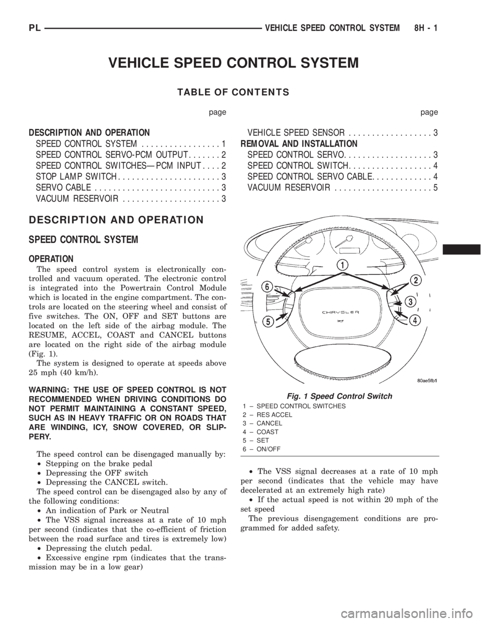
trols are located on the steering wheel and consist of
five switches. The ON, OFF and SET buttons are
located on the left side of the airbag module. The
RESUME, ACCEL, COAST and CANCEL buttons
are located on the right side of the airbag module
(Fig. 1).
The system is designed to operate at speeds above
25 mph (40 km/h).
WARNING: THE USE OF SPEED CONTROL IS NOT
RECOMMENDED WHEN DRIVING CONDITIONS DO
NOT PERMIT MAINTAINING A CONSTANT SPEED,
SUCH AS IN HEAVY TRAFFIC OR ON ROADS THAT
ARE WINDING, ICY, SNOW COVERED, OR SLIP-
PERY.
The speed control can be disengaged manually by:
²Stepping on the brake pedal
²Depressing the OFF switch
²Depressing the CANCEL switch.
The speed control can be disengaged also by any of
the following conditions:
²An indication of Park or Neutral
²The VSS signal increases at a rate of 10 mph
per second (indicates that the co-efficient of friction
between the road surface and tires is extremely low)
²Depressing the clutch pedal.
²Excessive engine rpm (indicates that the trans-
mission may be in a low gear)²The VSS signal decreases at a rate of 10 mph
per second (indicates that the vehicle may have
decelerated at an extremely high rate)
²If the actual speed is not within 20 mph of the
set speed
The previous disengagement conditions are pro-
grammed for added safety.
Fig. 1 Speed Control Switch
1 ± SPEED CONTROL SWITCHES
2 ± RES ACCEL
3 ± CANCEL
4 ± COAST
5 ± SET
6 ± ON/OFF
PLVEHICLE SPEED CONTROL SYSTEM 8H - 1
Page 288 of 1285
On most vehicles another resistor has been added
to the at rest circuit causing the PCM to never see 5
volts. This was done for diagnostic purposes. If the
switch circuit should open (bad connection) then the
PCM will see the 5 volts and know the circuit is bad.
The PCM will then set an open circuit fault.
STOP LAMP SWITCH
DESCRIPTION
The switch is mounted on the brake pedal mount-
ing bracket under the instrument panel.
OPERATION
Vehicles equipped with the speed control option use
a dual function stop lamp switch. The PCM monitors
the state of the dual function stop lamp switch. Refer
to the Brake section for more information on stop
lamp switch service and adjustment procedures.
The brake switch is equipped with three sets of
contacts, one normally open and the other two nor-
mally closed (brakes disengaged). The PCM sends a
12 volt signal to one of the normally closed contacts
in the brake switch, which is connected to a ground.
With the contacts closed, the 12 volt signal is pulled
to ground causing the signal to go low. The low volt-
age signal, monitored by the PCM, indicates that the
brakes are not applied. When the brakes are applied,
the contacts open, causing the PCM's output voltage
to go high, disengaging the speed control also
grounding the dump solenoid.
The second set of normally closed contacts is sup-
plied battery voltage any time speed control is
selected. From the brake switch, current is routed to
the speed control servo solenoids. The speed control
solenoids (vacuum, vent and dump) are provided this
current any time the speed control is ON and the
brakes are disengaged. When the driver applies the
brakes, the contacts open and current is interrupted
to the solenoids. The normally open contacts are fed
battery voltage. When the brakes are applied, battery
voltage is supplied to the stop lamps.
SERVO CABLE
DESCRIPTION
The speed control servo cable is connected between
the speed control vacuum servo diaphragm and the
throttle body control linkage.
OPERATION
This cable causes the throttle control linkage to
open or close the throttle valve in response to move-
ment of the vacuum servo diaphragm.
VACUUM RESERVOIR
OPERATION
The reservoir stores engine vacuum in the reser-
voir. When engine vacuum drops, as in climbing a
grade while driving, the reservoir supplies the vac-
uum needed to maintain proper speed control opera-
tion. The vacuum reservoir cannot be repaired and
must be replaced if faulty.
VEHICLE SPEED SENSOR
The Vehicle Speed Sensor (VSS) is a pulse genera-
tor mounted to an adapter near the transmission out-
put shaft. The sensor is driven through the adapter
by a speedometer pinion gear. The VSS pulse signal
to the speedometer/odometer is monitored by the
PCM speed control circuitry to determine vehicle
speed and to maintain speed control set speed.
REMOVAL AND INSTALLATION
SPEED CONTROL SERVO
REMOVAL
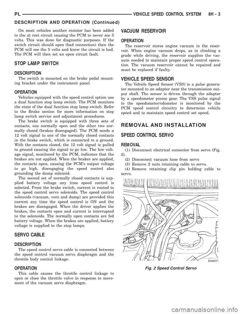
(1) Disconnect electrical connector from servo (Fig.
2).
(2) Disconnect vacuum hose from servo
(3) Remove 2 nuts retaining cable to servo.
(4) Remove retaining clip pin holding cable to
servo.
Fig. 2 Speed Control Servo
PLVEHICLE SPEED CONTROL SYSTEM 8H - 3
DESCRIPTION AND OPERATION (Continued)
Page 346 of 1285
PASSIVE RESTRAINT SYSTEMS
TABLE OF CONTENTS
page page
GENERAL INFORMATION
WARNINGS AND PRECAUTIONS.............1
DESCRIPTION AND OPERATION
AIRBAG CONTROL MODULE (ACM)..........1
CLOCKSPRING...........................2
DRIVER and PASSENGER AIRBAG MODULE....2
DIAGNOSIS AND TESTING
AIRBAG SYSTEM.........................3
SERVICE PROCEDURES
CLEAN UP PROCEDURE....................3HANDLING AIRBAG MODULES..............4
MAINTENANCE INSPECTION................4
REMOVAL AND INSTALLATION
AIRBAG CONTROL MODULE (ACM)..........4
CLOCKSPRING...........................5
DRIVER AIRBAG MODULE..................6
PASSENGER AIRBAG MODULE..............7
STEERING WHEEL........................8
ADJUSTMENTS
CLOCKSPRING CENTERING PROCEDURE......9
GENERAL INFORMATION
WARNINGS AND PRECAUTIONS
WARNING: THIS SYSTEM IS A SENSITIVE, COM-
PLEX ELECTRO±MECHANICAL UNIT. DISCONNECT
AND ISOLATE THE BATTERY NEGATIVE CABLE
BEFORE BEGINNING AIRBAG SYSTEM COMPO-
NENT REMOVAL OR INSTALLATION PROCEDURES.
THIS WILL DISABLE THE AIRBAG SYSTEM. FAIL-
URE TO DISCONNECT THE BATTERY COULD
RESULT IN ACCIDENTAL AIRBAG DEPLOYMENT
AND POSSIBLE PERSONAL INJURY.
ALLOW SYSTEM CAPACITOR TO DISCHARGE
FOR ONE MINUTE BEFORE REMOVING AIRBAG
COMPONENTS.
DO NOT PLACE AN INTACT UNDEPLOYED AIRBAG
FACE DOWN ON A SOLID SURFACE, THE AIRBAG
WILL PROPEL INTO THE AIR IF ACCIDENTALLY
DEPLOYED AND COULD RESULT IN PERSONAL
INJURY. WHEN CARRYING OR HANDLING AN UNDE-
PLOYED AIRBAG MODULE, THE TRIM SIDE OF THE
AIRBAG SHOULD BE POINTING AWAY FROM THE
BODY TO MINIMIZE POSSIBILITY OF INJURY IF ACCI-
DENTAL DEPLOYMENT OCCURS.
REPLACE AIRBAG SYSTEM COMPONENTS WITH
MOPARTREPLACEMENT PARTS. SUBSTITUTE
PARTS MAY APPEAR INTERCHANGEABLE, BUT
INTERNAL DIFFERENCES MAY RESULT IN INFE-
RIOR OCCUPANT PROTECTION.
WEAR SAFETY GLASSES, RUBBER GLOVES,
AND LONG SLEEVES CLOTHING WHEN CLEANING
POWDER RESIDUE FROM VEHICLE AFTER AIRBAG
DEPLOYMENT. SODIUM HYDROXIDE POWDER
RESIDUE EMITTED FROM A DEPLOYED AIRBAG
CAN CAUSE SKIN IRRITATION. FLUSH AFFECTEDAREA WITH COOL WATER IF IRRITATION IS EXPE-
RIENCED. IF NASAL OR THROAT IRRITATION IS
EXPERIENCED, EXIT THE VEHICLE FOR FRESH AIR
UNTIL THE IRRITATION CEASES. IF IRRITATION
CONTINUES, SEE A PHYSICIAN.
DO NOT USE A REPLACEMENT AIRBAG THAT IS
NOT IN THE ORIGINAL PACKAGING, IMPROPER
DEPLOYMENT AND PERSONAL INJURY CAN
RESULT.
THE FACTORY INSTALLED FASTENERS,
SCREWS AND BOLTS USED TO FASTEN AIRBAG
COMPONENTS HAVE A SPECIAL COATING AND
ARE SPECIFICALLY DESIGNED FOR THE AIRBAG
SYSTEM. DO NOT USE SUBSTITUTE FASTENERS,
USE ONLY ORIGINAL EQUIPMENT FASTENERS
LISTED IN THE PARTS CATALOG WHEN FASTENER
REPLACEMENT IS REQUIRED.
NOTE: Airbags should be stored in a cool dry loca-
tion away from excessive heat and static electrical
activity with the fabric airbag facing UP, or a prema-
ture deployment can result.
If the Driver/Passenger Airbag Module is defective
and not deployed, refer to DaimlerChrysler Corpora-
tion current return list for proper handling proce-
dures.
DESCRIPTION AND OPERATION
AIRBAG CONTROL MODULE (ACM)
The Airbag Control Module (ACM) contains the
sensing element, safing sensor, and energy reserve
capacitor. The module is mounted on the tunnel/floor
pan between the gear shift lever and the park brake
PLPASSIVE RESTRAINT SYSTEMS 8M - 1