2000 DODGE NEON brake sensor
[x] Cancel search: brake sensorPage 846 of 1285
²Air Conditioning Controls
²Battery Voltage
²Inlet Air/Battery Temperature Sensor
²Brake Switch
²Camshaft Position Sensor
²Crankshaft Position Sensor
²Engine Coolant Temperature Sensor
²Fuel Level Sensor
²Ignition Switch
²Inlet Air/Intake Air Temperature Sensor
²Knock Sensor
²Manifold Absolute Pressure (MAP) Sensor
²Oxygen Sensors
²Power Steering Pressure Switch²SCI Receive
²Speed Control Switches
²Throttle Position Sensor
²Transmission Park/Neutral Switch (automatic
transmission)
²Vehicle Speed Sensor
PCM Outputs:
²Air Conditioning WOT Relay
²Auto Shutdown (ASD) Relay
²Charging Indicator Lamp
²Data Link Connector
²Proportional Purge Solenoid
²EGR Solenoid
²Fuel Injectors
²Fuel Pump Relay
²Generator Field
²Idle Air Control Motor
²Ignition Coils
²Malfunction Indicator (Check Engine) Lamp
²Radiator Fan Relay
²Speed Control Solenoids
²Tachometer
²Torque Convertor Clutch Solenoid
Based on inputs it receives, the PCM adjusts fuel
injector pulse width, idle speed, ignition spark
advance, ignition coil dwell and EVAP canister purge
operation. The PCM regulates the cooling fan, air
conditioning and speed control systems. The PCM
changes generator charge rate by adjusting the gen-
erator field. The PCM also performs diagnostics.
The PCM adjusts injector pulse width (air-fuel
ratio) based on the following inputs.
²Battery voltage
²Coolant temperature
²Inlet Air/Intake air temperature
²Exhaust gas content (oxygen sensor)
²Engine speed (crankshaft position sensor)
²Manifold absolute pressure
²Throttle position
The PCM adjusts ignition timing based on the fol-
lowing inputs.
²Coolant temperature
²Inlet Air/Intake air temperature
²Engine speed (crankshaft position sensor)
²Knock sensor
²Manifold absolute pressure
²Throttle position
²Transmission gear selection (park/neutral
switch)
The PCM also adjusts engine idle speed through
the idle air control motor based on the following
inputs.
²Air conditioning sense
²Battery voltage
²Battery temperature
²Brake switch
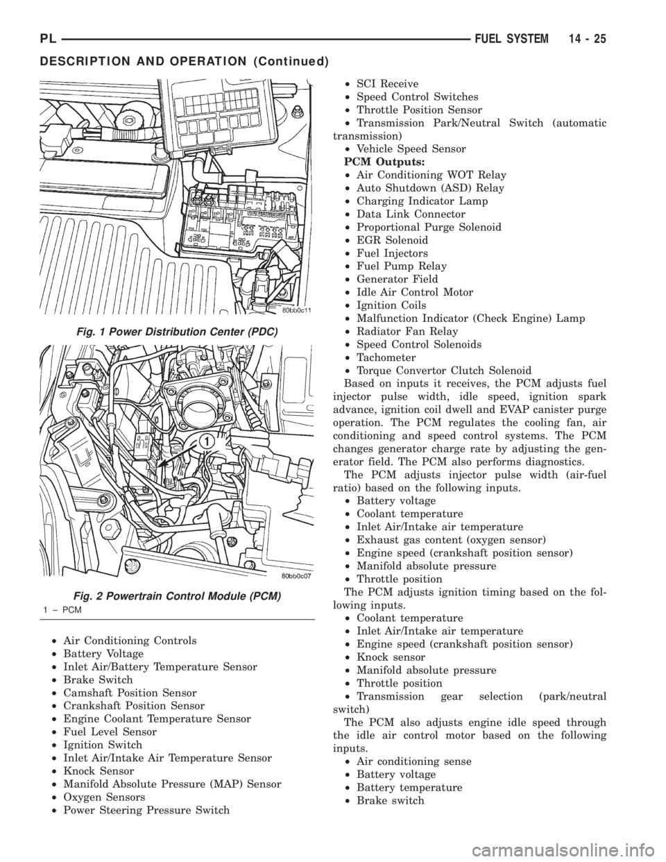
Fig. 1 Power Distribution Center (PDC)
Fig. 2 Powertrain Control Module (PCM)
1 ± PCM
PLFUEL SYSTEM 14 - 25
DESCRIPTION AND OPERATION (Continued)
Page 849 of 1285
BATTERY VOLTAGEÐPCM INPUT
OPERATION
In order for the PCM to operate, it must be sup-
plied with battery voltage and ground. The PCM
monitors the direct battery feed input to determine
battery charging rate and to control the injector ini-
tial opening point. It also has back-up RAM memory
used to store Diagnostic Trouble Codes (supply work-
ing DTCs). Direct battery feed is also used to perform
key-OFF diagnostics and to supply working voltage
to the controller for OBDII.
The five and eight volt regulators are protected
from shorts to ground. This protection allows diag-
nostics to be performed should the five volt power
supply become shorted to ground at any of the sen-
sors. A short to ground in the five volt power supply
will cause a ªno-startº situation. There is a Diagnos-
tic Trouble Code (DTC) if the five-volt power supply
becomes shorted to ground. Refer to the Diagnostic
Procedures Manual for more details on any on-board
diagnostic information.
If battery voltage is low the PCM will increase
injector pulse width (period of time that the injector
is energized).
The direct battery feed to the PCM is used as a
reference point to sense battery voltage.
Effect on Fuel Injectors
Fuel injectors are rated for operation at a specific
voltage. If the voltage increases, the plunger will
open faster and further (more efficient) and con-
versely, if voltage is low the injector will be slow to
open and will not open as far. Therefore, if sensed
battery voltage drops, the PCM increases injector
pulse-width to maintain the same volume of fuel
through the injector.
Charging
The PCM uses sensed battery voltage to verify that
target charging voltage (determined by Battery Tem-
perature Sensor) is being reached. To maintain the
target charging voltage, the PCM will full field the
generator to 0.5 volt above target then turn OFF to
0.5 volt below target. This will continue to occur up
to a 100 Hz frequency, 100 times per second.
BRAKE SWITCHÐPCM INPUT
OPERATION
When the brake switch is activated, the PCM
receives an input indicating that the brakes are
being applied. The brake switch is mounted on the
brake pedal support bracket.
CAMSHAFT POSITION SENSORÐPCM INPUT
DESCRIPTION
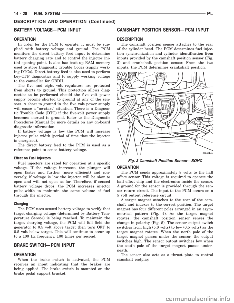
The camshaft position sensor attaches to the rear
of the cylinder head. The PCM determines fuel injec-
tion synchronization and cylinder identification from
inputs provided by the camshaft position sensor (Fig.
3) and crankshaft position sensor. From the two
inputs, the PCM determines crankshaft position.
OPERATION
The PCM sends approximately 8 volts to the hall
affect sensor. This voltage is required to operate the
hall effect chip and the electronics inside the sensor.
A ground for the sensor is provided through the sen-
sor return circuit. The input to the PCM occurs on a
5 volt output reference circuit.
A target magnet attaches to the rear of the cam-
shaft and indexes to the correct position. The target
magnet has four different poles arranged in an asym-
metrical pattern (Fig. 4). As the target magnet
rotates, the camshaft position sensor senses the
change in polarity (Fig. 5). The sensor output switch
switches from high (5.0 volts) to low (0.5 volts) as the
target magnet rotates. When the north pole of the
target magnet passes under the sensor, the output
switches high. The sensor output switches low when
the south pole of the target magnet passes under-
neath.
The sensor also acts as a thrust plate to control
camshaft endplay.
Fig. 3 Camshaft Position SensorÐSOHC
14 - 28 FUEL SYSTEMPL
DESCRIPTION AND OPERATION (Continued)
Page 850 of 1285
CLUTCH INTERLOCK/UPSTOP SWITCH
DESCRIPTION
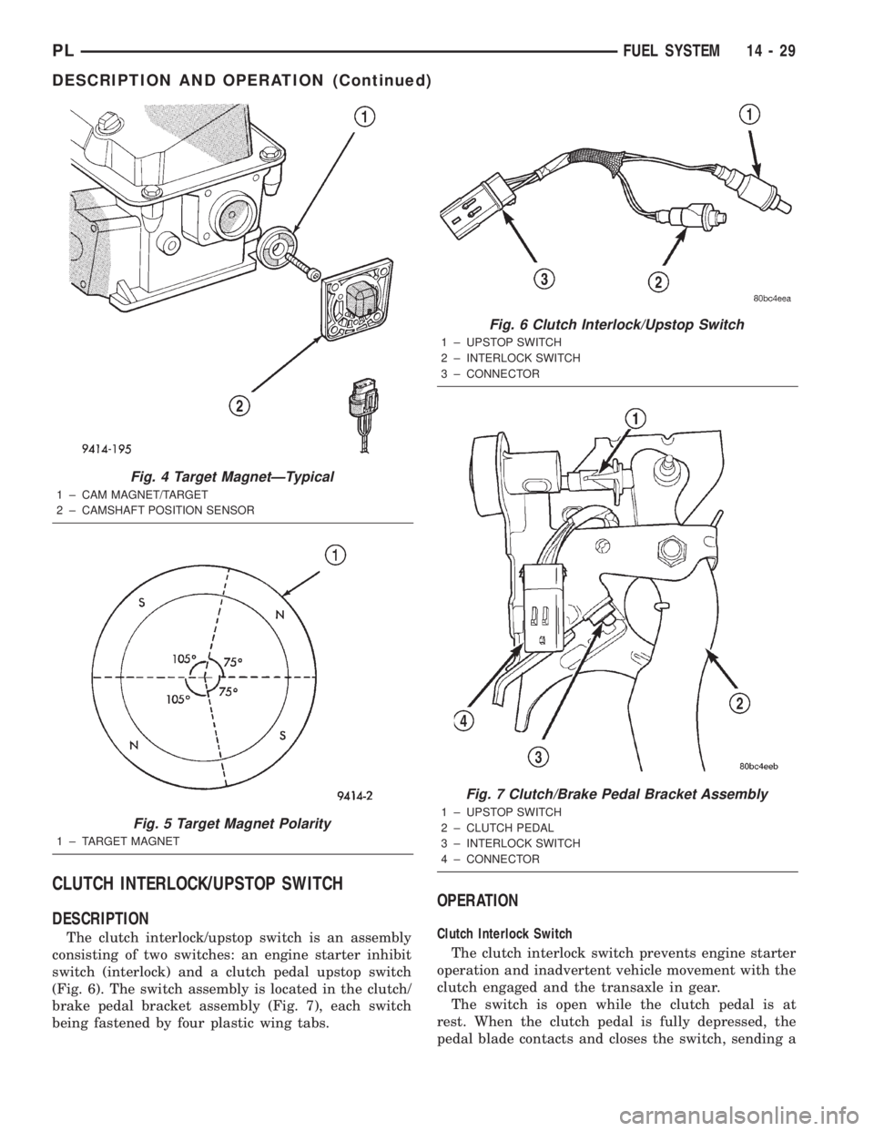
The clutch interlock/upstop switch is an assembly
consisting of two switches: an engine starter inhibit
switch (interlock) and a clutch pedal upstop switch
(Fig. 6). The switch assembly is located in the clutch/
brake pedal bracket assembly (Fig. 7), each switch
being fastened by four plastic wing tabs.
OPERATION
Clutch Interlock Switch
The clutch interlock switch prevents engine starter
operation and inadvertent vehicle movement with the
clutch engaged and the transaxle in gear.
The switch is open while the clutch pedal is at
rest. When the clutch pedal is fully depressed, the
pedal blade contacts and closes the switch, sending a
Fig. 4 Target MagnetÐTypical
1 ± CAM MAGNET/TARGET
2 ± CAMSHAFT POSITION SENSOR
Fig. 5 Target Magnet Polarity
1 ± TARGET MAGNET
Fig. 6 Clutch Interlock/Upstop Switch
1 ± UPSTOP SWITCH
2 ± INTERLOCK SWITCH
3 ± CONNECTOR
Fig. 7 Clutch/Brake Pedal Bracket Assembly
1 ± UPSTOP SWITCH
2 ± CLUTCH PEDAL
3 ± INTERLOCK SWITCH
4 ± CONNECTOR
PLFUEL SYSTEM 14 - 29
DESCRIPTION AND OPERATION (Continued)
Page 857 of 1285
The sensor return circuit connects to internal ground
circuits within the Powertrain Control Module
(PCM).
SPEED CONTROLÐPCM INPUT
OPERATION
The speed control system provides five separate
voltages (inputs) to the Powertrain Control Module
(PCM). The voltages correspond to the ON, OFF,
SET, RESUME, CANCEL, and COAST.
The speed control ON voltage informs the PCM
that the speed control system has been activated.
The speed control SET voltage informs the PCM that
a fixed vehicle speed has been selected. The speed
control RESUME voltage indicates the previous fixed
speed is requested. The speed control CANCEL volt-
age tells the PCM to deactivate but retain set speed
in memory (same as depressing the brake pedal). The
speed control OFF voltage tells the PCM that the
speed control system has deactivated.
Inputs Required for Operation
The inputs required by the PCM to operate the
Speed Control System include:
²Speed Control switches
²Brake switch
²Park/Neutral switch
²Vehicle speed signal
²Engine speed
²CCD bussed message from TCM
SCI RECEIVEÐPCM INPUT
OPERATION
SCI Receive is the serial data communication
receive circuit for the DRB scan tool. The PowertrainControl Module (PCM) receives data from the DRB
through the SCI Receive circuit.
PARK/NEUTRAL POSITION SWITCHÐPCM
INPUT
DESCRIPTION
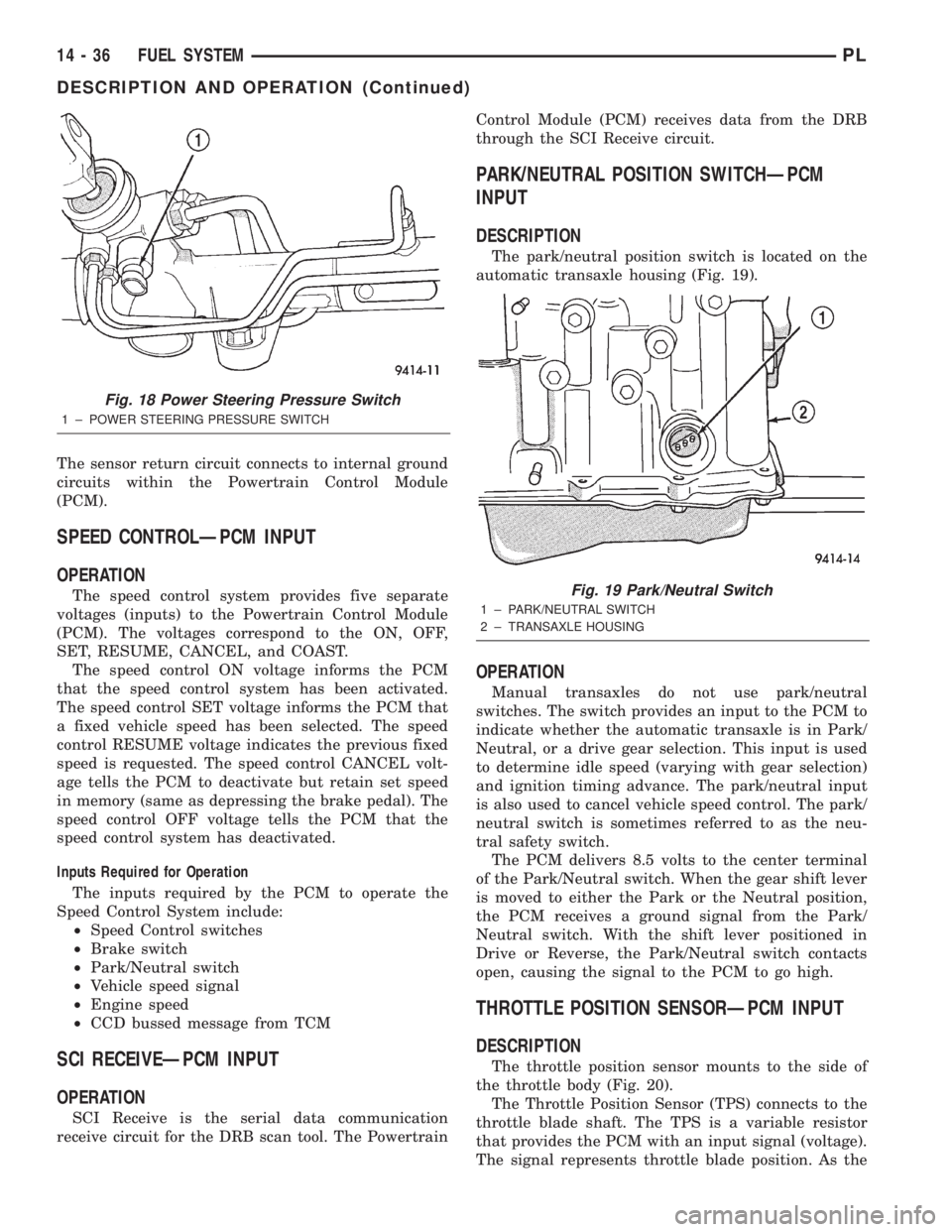
The park/neutral position switch is located on the
automatic transaxle housing (Fig. 19).
OPERATION
Manual transaxles do not use park/neutral
switches. The switch provides an input to the PCM to
indicate whether the automatic transaxle is in Park/
Neutral, or a drive gear selection. This input is used
to determine idle speed (varying with gear selection)
and ignition timing advance. The park/neutral input
is also used to cancel vehicle speed control. The park/
neutral switch is sometimes referred to as the neu-
tral safety switch.
The PCM delivers 8.5 volts to the center terminal
of the Park/Neutral switch. When the gear shift lever
is moved to either the Park or the Neutral position,
the PCM receives a ground signal from the Park/
Neutral switch. With the shift lever positioned in
Drive or Reverse, the Park/Neutral switch contacts
open, causing the signal to the PCM to go high.
THROTTLE POSITION SENSORÐPCM INPUT
DESCRIPTION
The throttle position sensor mounts to the side of
the throttle body (Fig. 20).
The Throttle Position Sensor (TPS) connects to the
throttle blade shaft. The TPS is a variable resistor
that provides the PCM with an input signal (voltage).
The signal represents throttle blade position. As the
Fig. 18 Power Steering Pressure Switch
1 ± POWER STEERING PRESSURE SWITCH
Fig. 19 Park/Neutral Switch
1 ± PARK/NEUTRAL SWITCH
2 ± TRANSAXLE HOUSING
14 - 36 FUEL SYSTEMPL
DESCRIPTION AND OPERATION (Continued)
Page 860 of 1285
PROPORTIONAL PURGE SOLENOIDÐPCM
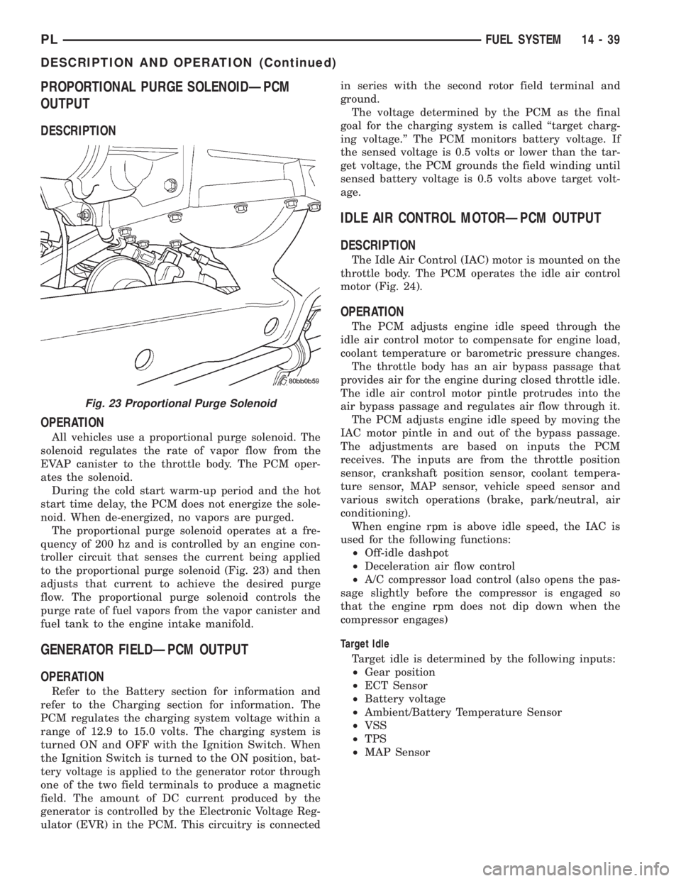
OUTPUT
DESCRIPTION
OPERATION
All vehicles use a proportional purge solenoid. The
solenoid regulates the rate of vapor flow from the
EVAP canister to the throttle body. The PCM oper-
ates the solenoid.
During the cold start warm-up period and the hot
start time delay, the PCM does not energize the sole-
noid. When de-energized, no vapors are purged.
The proportional purge solenoid operates at a fre-
quency of 200 hz and is controlled by an engine con-
troller circuit that senses the current being applied
to the proportional purge solenoid (Fig. 23) and then
adjusts that current to achieve the desired purge
flow. The proportional purge solenoid controls the
purge rate of fuel vapors from the vapor canister and
fuel tank to the engine intake manifold.
GENERATOR FIELDÐPCM OUTPUT
OPERATION
Refer to the Battery section for information and
refer to the Charging section for information. The
PCM regulates the charging system voltage within a
range of 12.9 to 15.0 volts. The charging system is
turned ON and OFF with the Ignition Switch. When
the Ignition Switch is turned to the ON position, bat-
tery voltage is applied to the generator rotor through
one of the two field terminals to produce a magnetic
field. The amount of DC current produced by the
generator is controlled by the Electronic Voltage Reg-
ulator (EVR) in the PCM. This circuitry is connectedin series with the second rotor field terminal and
ground.
The voltage determined by the PCM as the final
goal for the charging system is called ªtarget charg-
ing voltage.º The PCM monitors battery voltage. If
the sensed voltage is 0.5 volts or lower than the tar-
get voltage, the PCM grounds the field winding until
sensed battery voltage is 0.5 volts above target volt-
age.
IDLE AIR CONTROL MOTORÐPCM OUTPUT
DESCRIPTION
The Idle Air Control (IAC) motor is mounted on the
throttle body. The PCM operates the idle air control
motor (Fig. 24).
OPERATION
The PCM adjusts engine idle speed through the
idle air control motor to compensate for engine load,
coolant temperature or barometric pressure changes.
The throttle body has an air bypass passage that
provides air for the engine during closed throttle idle.
The idle air control motor pintle protrudes into the
air bypass passage and regulates air flow through it.
The PCM adjusts engine idle speed by moving the
IAC motor pintle in and out of the bypass passage.
The adjustments are based on inputs the PCM
receives. The inputs are from the throttle position
sensor, crankshaft position sensor, coolant tempera-
ture sensor, MAP sensor, vehicle speed sensor and
various switch operations (brake, park/neutral, air
conditioning).
When engine rpm is above idle speed, the IAC is
used for the following functions:
²Off-idle dashpot
²Deceleration air flow control
²A/C compressor load control (also opens the pas-
sage slightly before the compressor is engaged so
that the engine rpm does not dip down when the
compressor engages)
Target Idle
Target idle is determined by the following inputs:
²Gear position
²ECT Sensor
²Battery voltage
²Ambient/Battery Temperature Sensor
²VSS
²TPS
²MAP Sensor
Fig. 23 Proportional Purge Solenoid
PLFUEL SYSTEM 14 - 39
DESCRIPTION AND OPERATION (Continued)
Page 862 of 1285
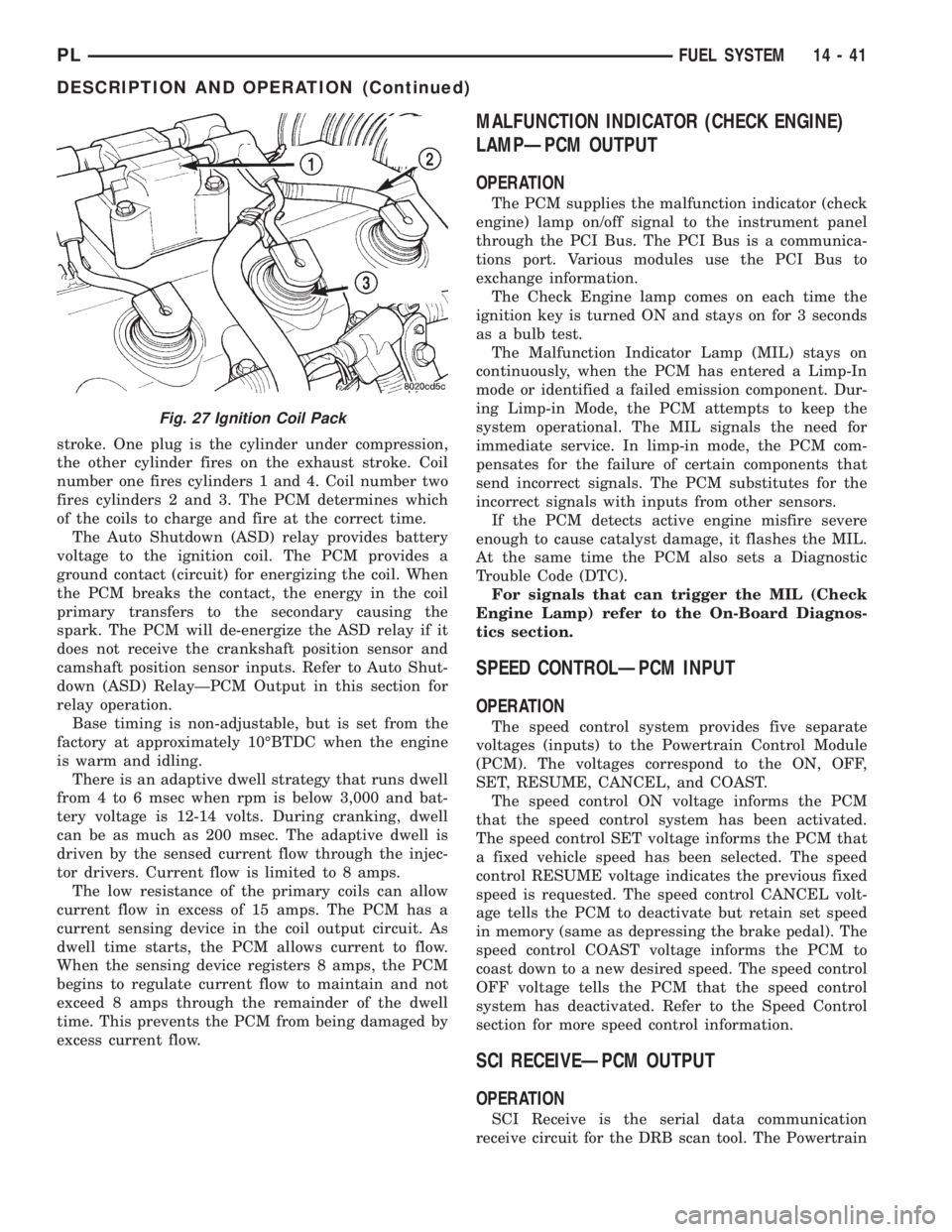
stroke. One plug is the cylinder under compression,
the other cylinder fires on the exhaust stroke. Coil
number one fires cylinders 1 and 4. Coil number two
fires cylinders 2 and 3. The PCM determines which
of the coils to charge and fire at the correct time.
The Auto Shutdown (ASD) relay provides battery
voltage to the ignition coil. The PCM provides a
ground contact (circuit) for energizing the coil. When
the PCM breaks the contact, the energy in the coil
primary transfers to the secondary causing the
spark. The PCM will de-energize the ASD relay if it
does not receive the crankshaft position sensor and
camshaft position sensor inputs. Refer to Auto Shut-
down (ASD) RelayÐPCM Output in this section for
relay operation.
Base timing is non-adjustable, but is set from the
factory at approximately 10ÉBTDC when the engine
is warm and idling.
There is an adaptive dwell strategy that runs dwell
from 4 to 6 msec when rpm is below 3,000 and bat-
tery voltage is 12-14 volts. During cranking, dwell
can be as much as 200 msec. The adaptive dwell is
driven by the sensed current flow through the injec-
tor drivers. Current flow is limited to 8 amps.
The low resistance of the primary coils can allow
current flow in excess of 15 amps. The PCM has a
current sensing device in the coil output circuit. As
dwell time starts, the PCM allows current to flow.
When the sensing device registers 8 amps, the PCM
begins to regulate current flow to maintain and not
exceed 8 amps through the remainder of the dwell
time. This prevents the PCM from being damaged by
excess current flow.
MALFUNCTION INDICATOR (CHECK ENGINE)
LAMPÐPCM OUTPUT
OPERATION
The PCM supplies the malfunction indicator (check
engine) lamp on/off signal to the instrument panel
through the PCI Bus. The PCI Bus is a communica-
tions port. Various modules use the PCI Bus to
exchange information.
The Check Engine lamp comes on each time the
ignition key is turned ON and stays on for 3 seconds
as a bulb test.
The Malfunction Indicator Lamp (MIL) stays on
continuously, when the PCM has entered a Limp-In
mode or identified a failed emission component. Dur-
ing Limp-in Mode, the PCM attempts to keep the
system operational. The MIL signals the need for
immediate service. In limp-in mode, the PCM com-
pensates for the failure of certain components that
send incorrect signals. The PCM substitutes for the
incorrect signals with inputs from other sensors.
If the PCM detects active engine misfire severe
enough to cause catalyst damage, it flashes the MIL.
At the same time the PCM also sets a Diagnostic
Trouble Code (DTC).
For signals that can trigger the MIL (Check
Engine Lamp) refer to the On-Board Diagnos-
tics section.
SPEED CONTROLÐPCM INPUT
OPERATION
The speed control system provides five separate
voltages (inputs) to the Powertrain Control Module
(PCM). The voltages correspond to the ON, OFF,
SET, RESUME, CANCEL, and COAST.
The speed control ON voltage informs the PCM
that the speed control system has been activated.
The speed control SET voltage informs the PCM that
a fixed vehicle speed has been selected. The speed
control RESUME voltage indicates the previous fixed
speed is requested. The speed control CANCEL volt-
age tells the PCM to deactivate but retain set speed
in memory (same as depressing the brake pedal). The
speed control COAST voltage informs the PCM to
coast down to a new desired speed. The speed control
OFF voltage tells the PCM that the speed control
system has deactivated. Refer to the Speed Control
section for more speed control information.
SCI RECEIVEÐPCM OUTPUT
OPERATION
SCI Receive is the serial data communication
receive circuit for the DRB scan tool. The Powertrain
Fig. 27 Ignition Coil Pack
PLFUEL SYSTEM 14 - 41
DESCRIPTION AND OPERATION (Continued)
Page 914 of 1285
TRANSAXLE
TABLE OF CONTENTS
page page
NV T350 (A-578) MANUAL TRANSAXLE........ 131TH AUTOMATIC TRANSAXLE.............. 54
NV T350 (A-578) MANUAL TRANSAXLE
TABLE OF CONTENTS
page page
GENERAL INFORMATION
NV T350 (A578) MANUAL TRANSAXLE.........1
TRANSAXLE IDENTIFICATION................2
FLUID REQUIREMENTS....................2
SPECIAL ADDITIVES.......................2
SEALANTS..............................2
GEAR RATIOS............................2
GEARSHIFT PATTERN......................3
DIAGNOSIS AND TESTING
COMMON PROBLEM CAUSES...............3
HARD SHIFTING..........................3
NOISY OPERATION........................3
SLIPS OUT OF GEAR......................3
LOW LUBRICANT LEVEL....................4
FLUID LEAKS............................4
CLUTCH PROBLEMS.......................4
SERVICE PROCEDURES
FLUID DRAIN AND FILL.....................4
REMOVAL AND INSTALLATION
GEARSHIFT KNOB........................4
GEARSHIFT BOOT........................5
GEARSHIFT CABLE ASSEMBLY..............6
GEARSHIFT MECHANISM REPLACEMENT......9
VEHICLE SPEED SENSOR AND DRIVE
PINION...............................11
BACK-UP LAMP SWITCH...................12CROSSOVER LEVER......................12
SELECTOR LEVER.......................12
AXLE SHAFT SEALS......................13
SHIFT SHAFT SEALS......................13
TRANSAXLE............................14
DISASSEMBLY AND ASSEMBLY
TRANSAXLE............................18
INPUT SHAFT...........................31
OUTPUT SHAFT.........................36
DIFFERENTIAL..........................36
SYNCHRONIZER.........................41
SHIFT RAILS OVERHAUL..................42
TRANSAXLE CASE OVERHAUL..............42
CLEANING AND INSPECTION
TRANSAXLE............................48
SYNCHRONIZER.........................48
ADJUSTMENTS
GEARSHIFT CROSSOVER CABLE...........49
BEARING ADJUSTMENT PROCEDURE........50
DIFFERENTIAL BEARING PRELOAD
ADJUSTMENT..........................50
SPECIFICATIONS
NV T350 (A-578) SPECIFICATIONS...........51
SPECIAL TOOLS
NV T350 (A-578) MANUAL TRANSAXLE........52
GENERAL INFORMATION
NV T350 (A578) MANUAL TRANSAXLE
The NV T350 (A-578) transaxle is a fully synchro-
nized (except reverse), constant-mesh transaxle. The
transaxle case is constructed of die-cast aluminum,
and is a two-piece design (bell housing case half and
rear housing case half) with a steel end plate bearing
cover. All forward gears are in constant-mesh witheach other, which eliminates the need to move gears
together for engagement. This feature improves
response and eliminates gear ªclashº noises. The
reverse idler gear is supported and rotates on a spin-
dle idler shaft. Depending on application, a reverse
gear brake/blocking ring is available on some units
for shifting ease.
The NV T350 (A-578) transaxle also incorporates an
open differential, which converts power from the output
shaft pinion gear to the differential ring gear. The dif-
PLTRANSAXLE 21 - 1
Page 967 of 1285
31TH AUTOMATIC TRANSAXLE
TABLE OF CONTENTS
page page
GENERAL INFORMATION
IN VEHICLE SERVICE.....................55
FLUID REQUIREMENTS...................55
DESCRIPTION AND OPERATION
31TH GENERAL INFORMATION..............55
FLUID LEVEL AND CONDITION..............56
TORQUE CONVERTER CLUTCH.............56
HYDRAULIC CONTROL SYSTEM.............56
PRESSURE SUPPLY SYSTEM...............56
PRESSURE REGULATING VALVES...........56
FLOW CONTROL VALVES..................56
CLUTCHES, BAND SERVOS, AND
ACCUMULATOR........................57
BRAKE TRANSMISSION SHIFT INTERLOCK
SYSTEM..............................57
GEARSHIFT AND PARKING LOCK CONTROLS . . 57
COOLER BYPASS VALVE..................57
TORQUE CONVERTER CLUTCH SOLENOID
WIRING CONNECTOR...................58
GOVERNOR.............................58
DIAGNOSIS AND TESTING
TRANSAXLE PRELIMINARY DIAGNOSIS.......58
ROAD TEST.............................65
HYDRAULIC PRESSURE TESTS.............66
CLUTCH AND SERVO AIR PRESSURE TESTS . . 68
FLUID LEAKAGE-TRANSAXLE TORQUE
CONVERTER HOUSING AREA.............70
BRAKE TRANSMISSION SHIFT INTERLOCK....70
SERVICE PROCEDURES
TRANSAXLE FLUID AND FILTER SERVICE.....70
ALUMINUM THREAD REPAIR...............71
FLUSHING COOLERS AND TUBES...........72
OIL PUMP VOLUME CHECK................72
REMOVAL AND INSTALLATION
GEARSHIFT CABLE.......................73
GEARSHIFT MECHANISM..................76
THROTTLE VALVE (KICKDOWN) CABLE.......77
BRAKE TRANSMISSION SHIFT INTERLOCK
CABLE...............................79
INTERLOCK MECHANISM..................82
VEHICLE SPEED SENSOR PINION GEAR......83
PARK/NEUTRAL STARTING AND BACK-UP
LAMP SWITCH.........................84TRANSAXLE AND TORQUE CONVERTER......84
PUMP OIL SEAL.........................88
DISASSEMBLY AND ASSEMBLY
TRANSAXLE............................89
VALVE BODY............................91
OIL PUMP.............................104
FRONT CLUTCH........................105
REAR CLUTCH ASSEMBLY................108
FRONT PLANETARY AND ANNULUS
GEAR-RECONDITION...................110
LOW/REVERSE (REAR) SERVO-
RECONDITION........................112
ACCUMULATOR-RECONDITION............113
KICKDOWN SERVO (CONTROLLED LOAD)-
RECONDITION........................113
TRANSFER SHAFT REPAIR................114
PARKING PAWL.........................121
OUTPUT SHAFT REPAIR..................121
DIFFERENTIAL REPAIR...................129
CLEANING AND INSPECTION
VALVE BODY...........................135
ADJUSTMENTS
GEARSHIFT CABLE......................135
THROTTLE VALVE CABLE ADJUSTMENT
PROCEDURE.........................136
BRAKE TRANSMISSION SHIFT INTERLOCK
SYSTEM.............................137
BAND ADJUSTMENT.....................138
HYDRAULIC CONTROL PRESSURE
ADJUSTMENTS.......................138
BEARING ADJUSTMENT PROCEDURES......138
OUTPUT SHAFT BEARING................139
DIFFERENTIAL BEARING.................139
TRANSFER SHAFT BEARING..............140
SCHEMATICS AND DIAGRAMS
31TH TRANSAXLE HYDRAULIC SCHEMATIC . . 142
SPECIFICATIONS
31TH AUTOMATIC TRANSAXLE.............150
31TH TRANSAXLE TORQUE SPECIFICATIONS . 150
SPECIAL TOOLS
31TH AUTOMATIC TRANSAXLE.............151
21 - 54 TRANSAXLEPL