2000 DODGE NEON brake sensor
[x] Cancel search: brake sensorPage 659 of 1285
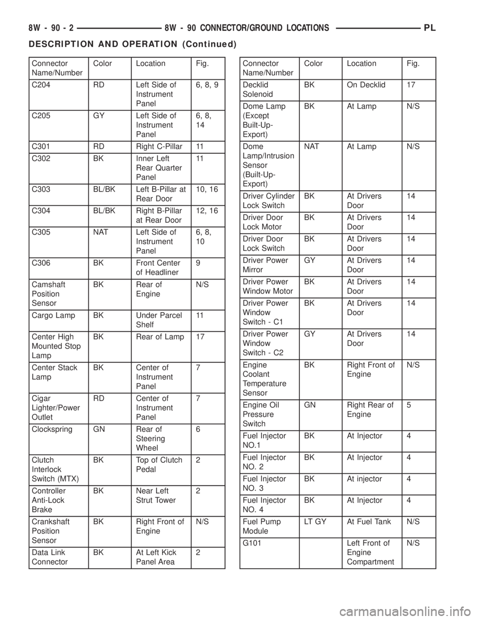
Connector
Name/NumberColor Location Fig.
C204 RD Left Side of
Instrument
Panel6, 8, 9
C205 GY Left Side of
Instrument
Panel6, 8,
14
C301 RD Right C-Pillar 11
C302 BK Inner Left
Rear Quarter
Panel11
C303 BL/BK Left B-Pillar at
Rear Door10, 16
C304 BL/BK Right B-Pillar
at Rear Door12, 16
C305 NAT Left Side of
Instrument
Panel6, 8,
10
C306 BK Front Center
of Headliner9
Camshaft
Position
SensorBK Rear of
EngineN/S
Cargo Lamp BK Under Parcel
Shelf11
Center High
Mounted Stop
LampBK Rear of Lamp 17
Center Stack
LampBK Center of
Instrument
Panel7
Cigar
Lighter/Power
OutletRD Center of
Instrument
Panel7
Clockspring GN Rear of
Steering
Wheel6
Clutch
Interlock
Switch (MTX)BK Top of Clutch
Pedal2
Controller
Anti-Lock
BrakeBK Near Left
Strut Tower2
Crankshaft
Position
SensorBK Right Front of
EngineN/S
Data Link
ConnectorBK At Left Kick
Panel Area2Connector
Name/NumberColor Location Fig.
Decklid
SolenoidBK On Decklid 17
Dome Lamp
(Except
Built-Up-
Export)BK At Lamp N/S
Dome
Lamp/Intrusion
Sensor
(Built-Up-
Export)NAT At Lamp N/S
Driver Cylinder
Lock SwitchBK At Drivers
Door14
Driver Door
Lock MotorBK At Drivers
Door14
Driver Door
Lock SwitchBK At Drivers
Door14
Driver Power
MirrorGY At Drivers
Door14
Driver Power
Window MotorBK At Drivers
Door14
Driver Power
Window
Switch - C1BK At Drivers
Door14
Driver Power
Window
Switch - C2GY At Drivers
Door14
Engine
Coolant
Temperature
SensorBK Right Front of
EngineN/S
Engine Oil
Pressure
SwitchGN Right Rear of
Engine5
Fuel Injector
NO.1BK At Injector 4
Fuel Injector
NO. 2BK At Injector 4
Fuel Injector
NO. 3BK At injector 4
Fuel Injector
NO. 4BK At Injector 4
Fuel Pump
ModuleLT GY At Fuel Tank N/S
G101 Left Front of
Engine
CompartmentN/S
8W - 90 - 2 8W - 90 CONNECTOR/GROUND LOCATIONSPL
DESCRIPTION AND OPERATION (Continued)
Page 679 of 1285
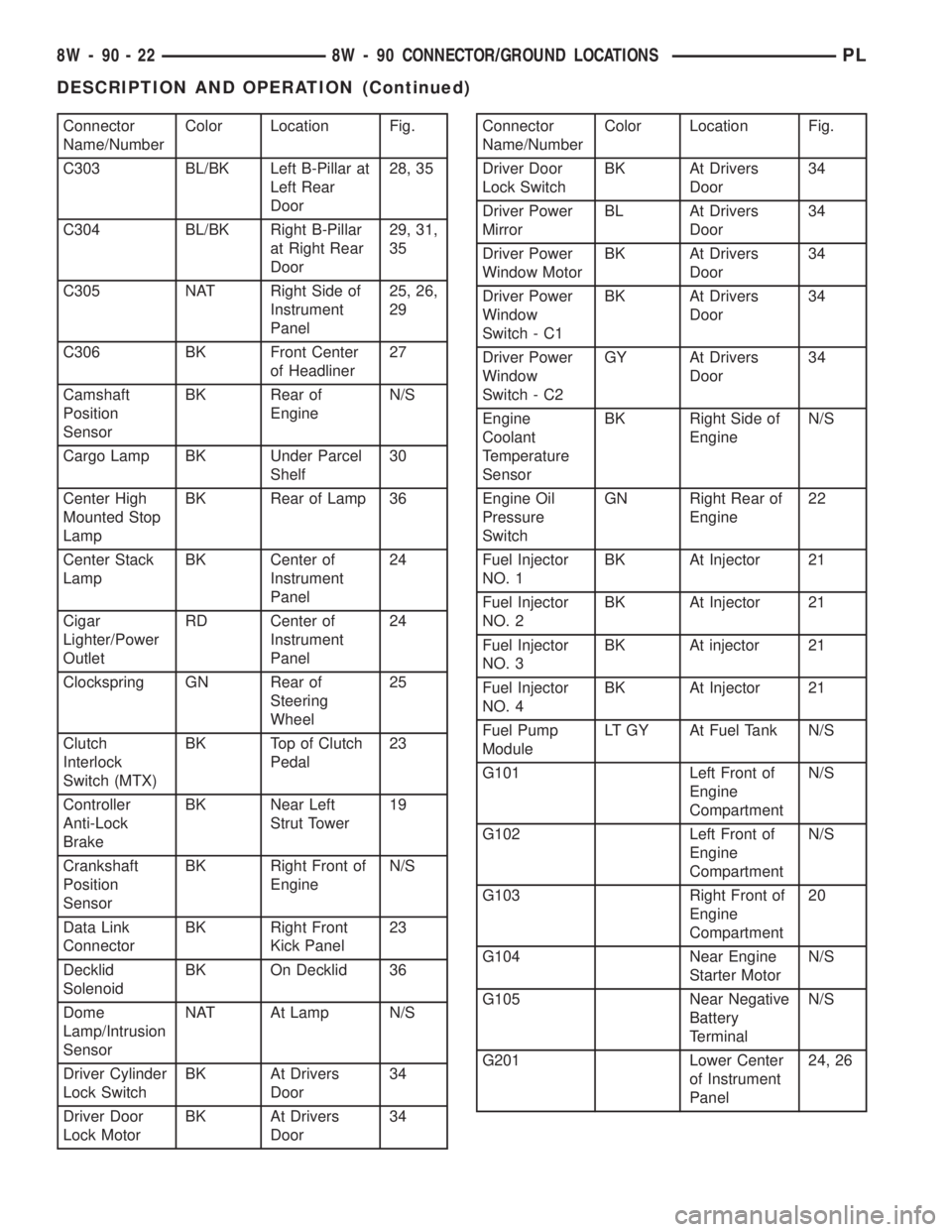
Connector
Name/NumberColor Location Fig.
C303 BL/BK Left B-Pillar at
Left Rear
Door28, 35
C304 BL/BK Right B-Pillar
at Right Rear
Door29, 31,
35
C305 NAT Right Side of
Instrument
Panel25, 26,
29
C306 BK Front Center
of Headliner27
Camshaft
Position
SensorBK Rear of
EngineN/S
Cargo Lamp BK Under Parcel
Shelf30
Center High
Mounted Stop
LampBK Rear of Lamp 36
Center Stack
LampBK Center of
Instrument
Panel24
Cigar
Lighter/Power
OutletRD Center of
Instrument
Panel24
Clockspring GN Rear of
Steering
Wheel25
Clutch
Interlock
Switch (MTX)BK Top of Clutch
Pedal23
Controller
Anti-Lock
BrakeBK Near Left
Strut Tower19
Crankshaft
Position
SensorBK Right Front of
EngineN/S
Data Link
ConnectorBK Right Front
Kick Panel23
Decklid
SolenoidBK On Decklid 36
Dome
Lamp/Intrusion
SensorNAT At Lamp N/S
Driver Cylinder
Lock SwitchBK At Drivers
Door34
Driver Door
Lock MotorBK At Drivers
Door34Connector
Name/NumberColor Location Fig.
Driver Door
Lock SwitchBK At Drivers
Door34
Driver Power
MirrorBL At Drivers
Door34
Driver Power
Window MotorBK At Drivers
Door34
Driver Power
Window
Switch - C1BK At Drivers
Door34
Driver Power
Window
Switch - C2GY At Drivers
Door34
Engine
Coolant
Temperature
SensorBK Right Side of
EngineN/S
Engine Oil
Pressure
SwitchGN Right Rear of
Engine22
Fuel Injector
NO. 1BK At Injector 21
Fuel Injector
NO. 2BK At Injector 21
Fuel Injector
NO. 3BK At injector 21
Fuel Injector
NO. 4BK At Injector 21
Fuel Pump
ModuleLT GY At Fuel Tank N/S
G101 Left Front of
Engine
CompartmentN/S
G102 Left Front of
Engine
CompartmentN/S
G103 Right Front of
Engine
Compartment20
G104 Near Engine
Starter MotorN/S
G105 Near Negative
Battery
TerminalN/S
G201 Lower Center
of Instrument
Panel24, 26
8W - 90 - 22 8W - 90 CONNECTOR/GROUND LOCATIONSPL
DESCRIPTION AND OPERATION (Continued)
Page 698 of 1285
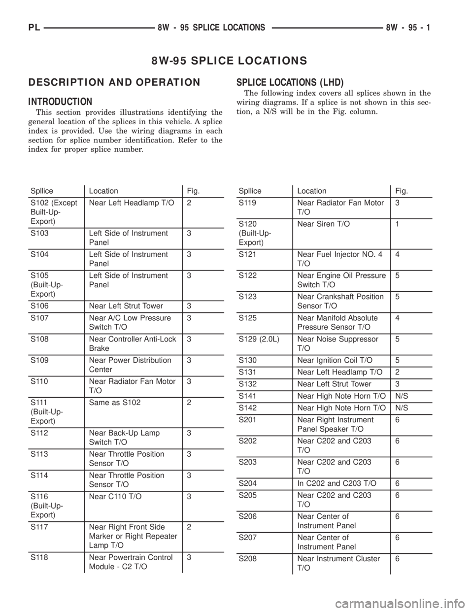
8W-95 SPLICE LOCATIONS
DESCRIPTION AND OPERATION
INTRODUCTION
This section provides illustrations identifying the
general location of the splices in this vehicle. A splice
index is provided. Use the wiring diagrams in each
section for splice number identification. Refer to the
index for proper splice number.
SPLICE LOCATIONS (LHD)
The following index covers all splices shown in the
wiring diagrams. If a splice is not shown in this sec-
tion, a N/S will be in the Fig. column.
Spllice Location Fig.
S102 (Except
Built-Up-
Export)Near Left Headlamp T/O 2
S103 Left Side of Instrument
Panel3
S104 Left Side of Instrument
Panel3
S105
(Built-Up-
Export)Left Side of Instrument
Panel3
S106 Near Left Strut Tower 3
S107 Near A/C Low Pressure
Switch T/O3
S108 Near Controller Anti-Lock
Brake3
S109 Near Power Distribution
Center3
S110 Near Radiator Fan Motor
T/O3
S 111
(Built-Up-
Export)Same as S102 2
S112 Near Back-Up Lamp
Switch T/O3
S113 Near Throttle Position
Sensor T/O3
S114 Near Throttle Position
Sensor T/O3
S116
(Built-Up-
Export)Near C110 T/O 3
S117 Near Right Front Side
Marker or Right Repeater
Lamp T/O2
S118 Near Powertrain Control
Module - C2 T/O3Spllice Location Fig.
S119 Near Radiator Fan Motor
T/O3
S120
(Built-Up-
Export)Near Siren T/O 1
S121 Near Fuel Injector NO. 4
T/O4
S122 Near Engine Oil Pressure
Switch T/O5
S123 Near Crankshaft Position
Sensor T/O5
S125 Near Manifold Absolute
Pressure Sensor T/O4
S129 (2.0L) Near Noise Suppressor
T/O5
S130 Near Ignition Coil T/O 5
S131 Near Left Headlamp T/O 2
S132 Near Left Strut Tower 3
S141 Near High Note Horn T/O N/S
S142 Near High Note Horn T/O N/S
S201 Near Right Instrument
Panel Speaker T/O6
S202 Near C202 and C203
T/O6
S203 Near C202 and C203
T/O6
S204 In C202 and C203 T/O 6
S205 Near C202 and C203
T/O6
S206 Near Center of
Instrument Panel6
S207 Near Center of
Instrument Panel6
S208 Near Instrument Cluster
T/O6
PL8W - 95 SPLICE LOCATIONS 8W - 95 - 1
Page 710 of 1285
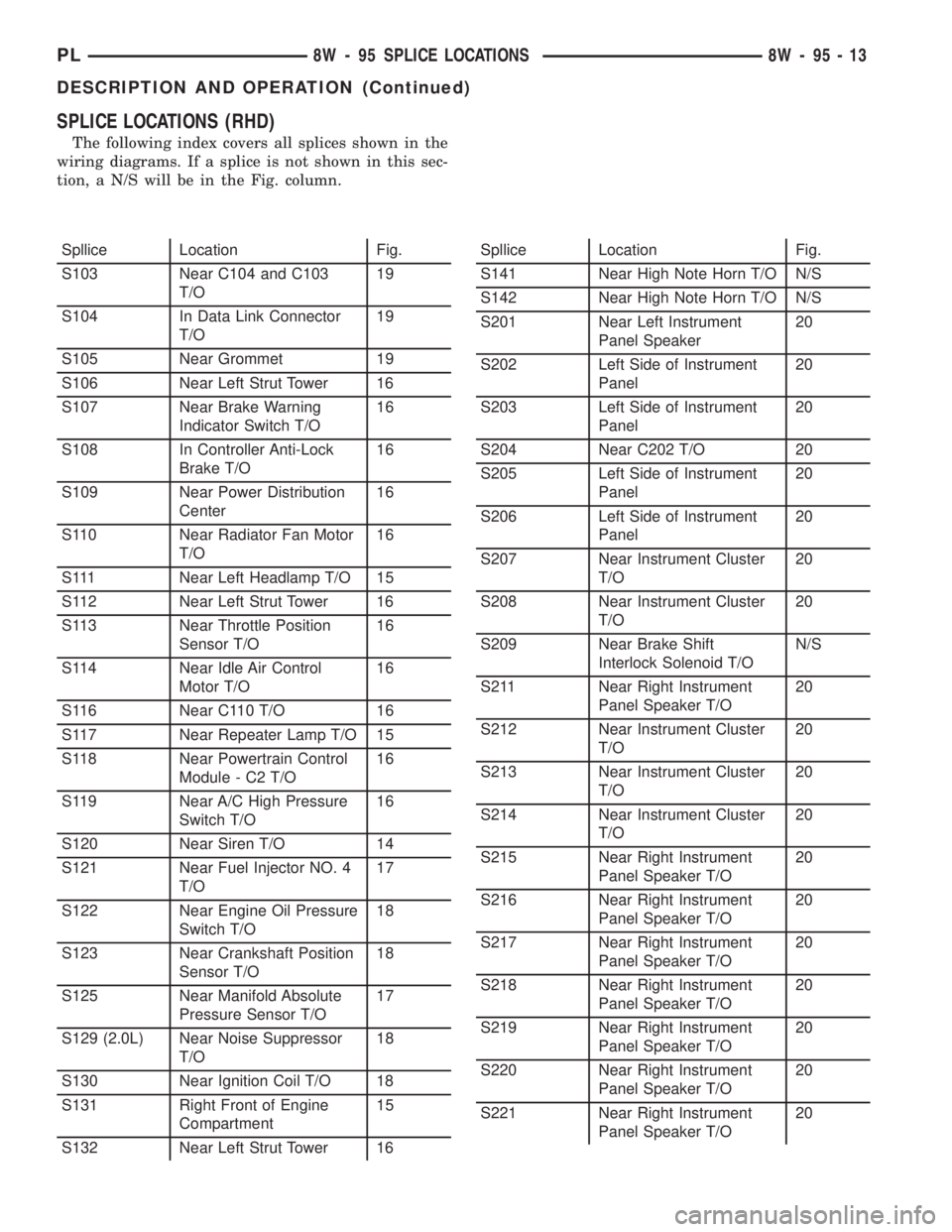
SPLICE LOCATIONS (RHD)
The following index covers all splices shown in the
wiring diagrams. If a splice is not shown in this sec-
tion, a N/S will be in the Fig. column.
Spllice Location Fig.
S103 Near C104 and C103
T/O19
S104 In Data Link Connector
T/O19
S105 Near Grommet 19
S106 Near Left Strut Tower 16
S107 Near Brake Warning
Indicator Switch T/O16
S108 In Controller Anti-Lock
Brake T/O16
S109 Near Power Distribution
Center16
S110 Near Radiator Fan Motor
T/O16
S111 Near Left Headlamp T/O 15
S112 Near Left Strut Tower 16
S113 Near Throttle Position
Sensor T/O16
S114 Near Idle Air Control
Motor T/O16
S116 Near C110 T/O 16
S117 Near Repeater Lamp T/O 15
S118 Near Powertrain Control
Module - C2 T/O16
S119 Near A/C High Pressure
Switch T/O16
S120 Near Siren T/O 14
S121 Near Fuel Injector NO. 4
T/O17
S122 Near Engine Oil Pressure
Switch T/O18
S123 Near Crankshaft Position
Sensor T/O18
S125 Near Manifold Absolute
Pressure Sensor T/O17
S129 (2.0L) Near Noise Suppressor
T/O18
S130 Near Ignition Coil T/O 18
S131 Right Front of Engine
Compartment15
S132 Near Left Strut Tower 16Spllice Location Fig.
S141 Near High Note Horn T/O N/S
S142 Near High Note Horn T/O N/S
S201 Near Left Instrument
Panel Speaker20
S202 Left Side of Instrument
Panel20
S203 Left Side of Instrument
Panel20
S204 Near C202 T/O 20
S205 Left Side of Instrument
Panel20
S206 Left Side of Instrument
Panel20
S207 Near Instrument Cluster
T/O20
S208 Near Instrument Cluster
T/O20
S209 Near Brake Shift
Interlock Solenoid T/ON/S
S211 Near Right Instrument
Panel Speaker T/O20
S212 Near Instrument Cluster
T/O20
S213 Near Instrument Cluster
T/O20
S214 Near Instrument Cluster
T/O20
S215 Near Right Instrument
Panel Speaker T/O20
S216 Near Right Instrument
Panel Speaker T/O20
S217 Near Right Instrument
Panel Speaker T/O20
S218 Near Right Instrument
Panel Speaker T/O20
S219 Near Right Instrument
Panel Speaker T/O20
S220 Near Right Instrument
Panel Speaker T/O20
S221 Near Right Instrument
Panel Speaker T/O20
PL8W - 95 SPLICE LOCATIONS 8W - 95 - 13
DESCRIPTION AND OPERATION (Continued)
Page 749 of 1285
(4) Discharge air conditioning system, if equipped.
Refer to Group 24, Heating and Air Conditioning for
procedure.
(5) Disconnect the following: air intake duct at
intake manifold, throttle cables, electrical connectors
from throttle body and air cleaner housing.
(6) Remove air cleaner housing assembly.
(7) Remove upper radiator hose and fan module.
Refer to Group 7, Cooling System for procedure.
(8) Remove lower radiator hose.
(9) Disconnect automatic transmission cooler lines
and plug, if equipped.
(10) Disconnect shift linkage, electrical connectors,
and clutch cable, if equipped with manual transaxle.
(11) Disconnect engine wiring harness.
(12) Disconnect positive cable from Power Distri-
bution Center (PDC) and ground wire from vehicle
body.
(13) Disconnect ground wire from the vehicle body-
to-engine at the right side strut tower.
(14) Disconnect heater hoses.
(15) Disconnect vacuum hose from brake booster.
(16) Disconnect coolant reserve/recovery hose.
(17) Remove accessory drive belts. Refer to Group
7, Cooling System for procedure.
(18) Remove power steering pump and reservoir
and set them aside.
(19) Hoist vehicle and remove right inner splash
shield.
(20) Drain engine oil.
(21) Remove front wheels.
(22) Remove axle shafts. Refer to Group 3, Differ-
ential and Driveline for procedure.
(23) Disconnect exhaust system from manifold.
(24) Disconnect the downstream oxygen sensor
connector.
(25) Remove lower engine torque strut.
(26) Remove structural collar. Refer to procedure
in this section.
(27) Lower vehicle and remove A/C compressor.
(28) Raise vehicle enough to allow engine dolly
and cradle, Special Tools 6135 and 6710 to be
installed under vehicle.
(29) Loosen engine support posts to allow move-
ment for positioning onto engine locating holes and
flange on the engine bedplate. Lower vehicle and
position cradle until the engine is resting on support
posts (Fig. 26). Tighten mounts to cradle frame. This
will keep support posts from moving when removing
or installing engine and transmission.
(30) Install safety straps around the engine to cra-
dle (Fig. 26). Tighten straps and lock them into posi-
tion.
WARNING: Safety straps MUST be used.(31) Raise vehicle enough to see if straps are tight
enough to hold cradle assembly to engine.
(32) Lower vehicle so weight of the engine and
transmission ONLY is on the cradle assembly.
(33) Remove the upper engine torque strut.
(34) Remove right and left engine and transaxle
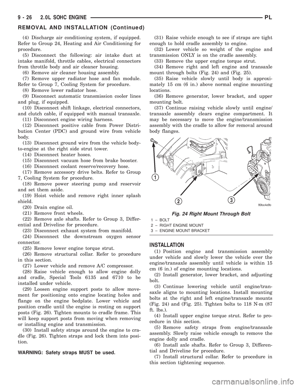
mount through bolts (Fig. 24) and (Fig. 25).
(35) Raise vehicle slowly until body is approxi-
mately 15 cm (6 in.) above normal engine mounting
locations.
(36) Remove generator, lower bracket, and upper
mounting bolt.
(37) Continue raising vehicle slowly until engine/
transaxle assembly clears engine compartment. It
may be necessary to move the engine/transmission
assembly with the cradle to allow for removal around
body flanges.
INSTALLATION
(1) Position engine and transmission assembly
under vehicle and slowly lower the vehicle over the
engine/transaxle assembly until vehicle is within 15
cm (6 in.) of engine mounting locations.
(2) Install generator, lower bracket, and adjusting
bolt.
(3) Continue lowering vehicle until engine/tran-
saxle aligns to mounting locations. Install mounting
bolts at the right and left engine/transaxle mounts
(Fig. 24) and (Fig. 25). Tighten bolts to 118 N´m (87
ft. lbs.).
(4) Install upper engine torque strut. Refer to pro-
cedure in this section.
(5) Remove safety straps from engine/transaxle
assembly. Slowly raise vehicle enough to remove the
engine dolly and cradle.
(6) Install axle shafts. Refer to Group 3, Differen-
tial and Driveline for procedure.
(7) Install structural collar. Refer to procedure in
this section tightening sequence.
Fig. 24 Right Mount Through Bolt
1 ± BOLT
2 ± RIGHT ENGINE MOUNT
3 ± ENGINE MOUNT BRACKET
9 - 26 2.0L SOHC ENGINEPL
REMOVAL AND INSTALLATION (Continued)
Page 751 of 1285
(27) Start engine and run until operating temper-
ature is reached.
(28) Ensure engine is properly positioned. Refer to
Torque Struts in this section for adjustment proce-
dure.
(29) Adjust transmission linkage, if necessary.
INTAKE MANIFOLD
REMOVAL
WARNING: RELEASE FUEL SYSTEM PRESSURE
BEFORE SERVICING FUEL SYSTEM COMPONENTS.
SERVICE VEHICLES IN WELL VENTILATED AREAS
AND AVOID IGNITION SOURCES. NEVER SMOKE
WHILE SERVICING THE VEHICLE.
(1) Disconnect negative cable from battery.
(2) Remove the inlet air duct from intake manifold
to throttle body.
(3) Perform fuel system pressure release procedure
before attempting any repairs.Refer to Group 14,
Fuel System for procedures.
WARNING: WRAP SHOP TOWELS AROUND FUEL
HOSE TO CATCH ANY GASOLINE SPILLAGE
(4) Disconnect fuel supply line quick connect at the
fuel tube assembly. Refer to Group 14, Fuel System
for procedures.
(5) Remove fuel rail assembly attaching screws
and remove fuel rail assembly from engine. Cover
injector holes with suitable covering.
CAUTION: Do not set fuel injectors on their tips,
damage may occur to the injectors
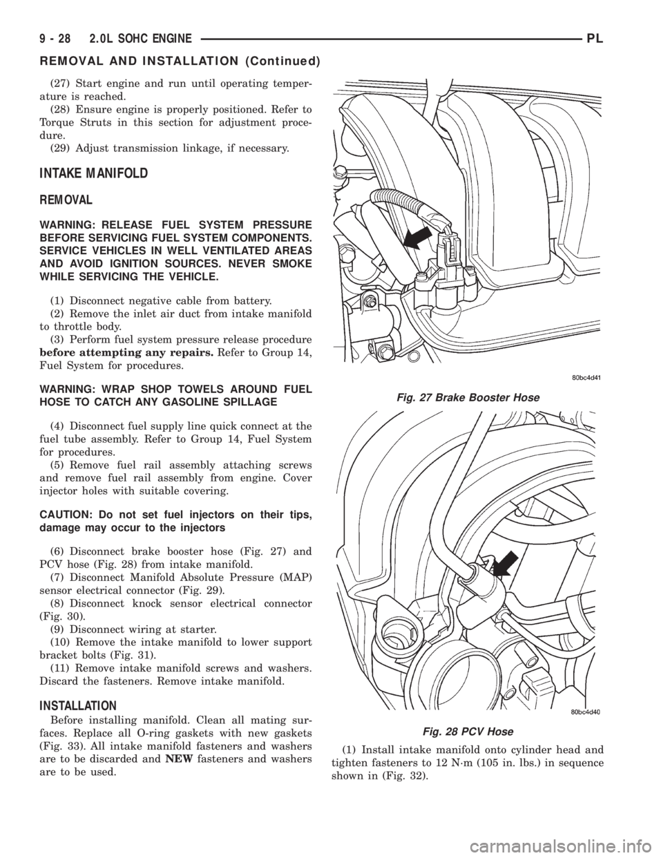
(6) Disconnect brake booster hose (Fig. 27) and
PCV hose (Fig. 28) from intake manifold.
(7) Disconnect Manifold Absolute Pressure (MAP)
sensor electrical connector (Fig. 29).
(8) Disconnect knock sensor electrical connector
(Fig. 30).
(9) Disconnect wiring at starter.
(10) Remove the intake manifold to lower support
bracket bolts (Fig. 31).
(11) Remove intake manifold screws and washers.
Discard the fasteners. Remove intake manifold.
INSTALLATION
Before installing manifold. Clean all mating sur-
faces. Replace all O-ring gaskets with new gaskets
(Fig. 33). All intake manifold fasteners and washers
are to be discarded andNEWfasteners and washers
are to be used.(1) Install intake manifold onto cylinder head and
tighten fasteners to 12 N´m (105 in. lbs.) in sequence
shown in (Fig. 32).
Fig. 27 Brake Booster Hose
Fig. 28 PCV Hose
9 - 28 2.0L SOHC ENGINEPL
REMOVAL AND INSTALLATION (Continued)
Page 752 of 1285
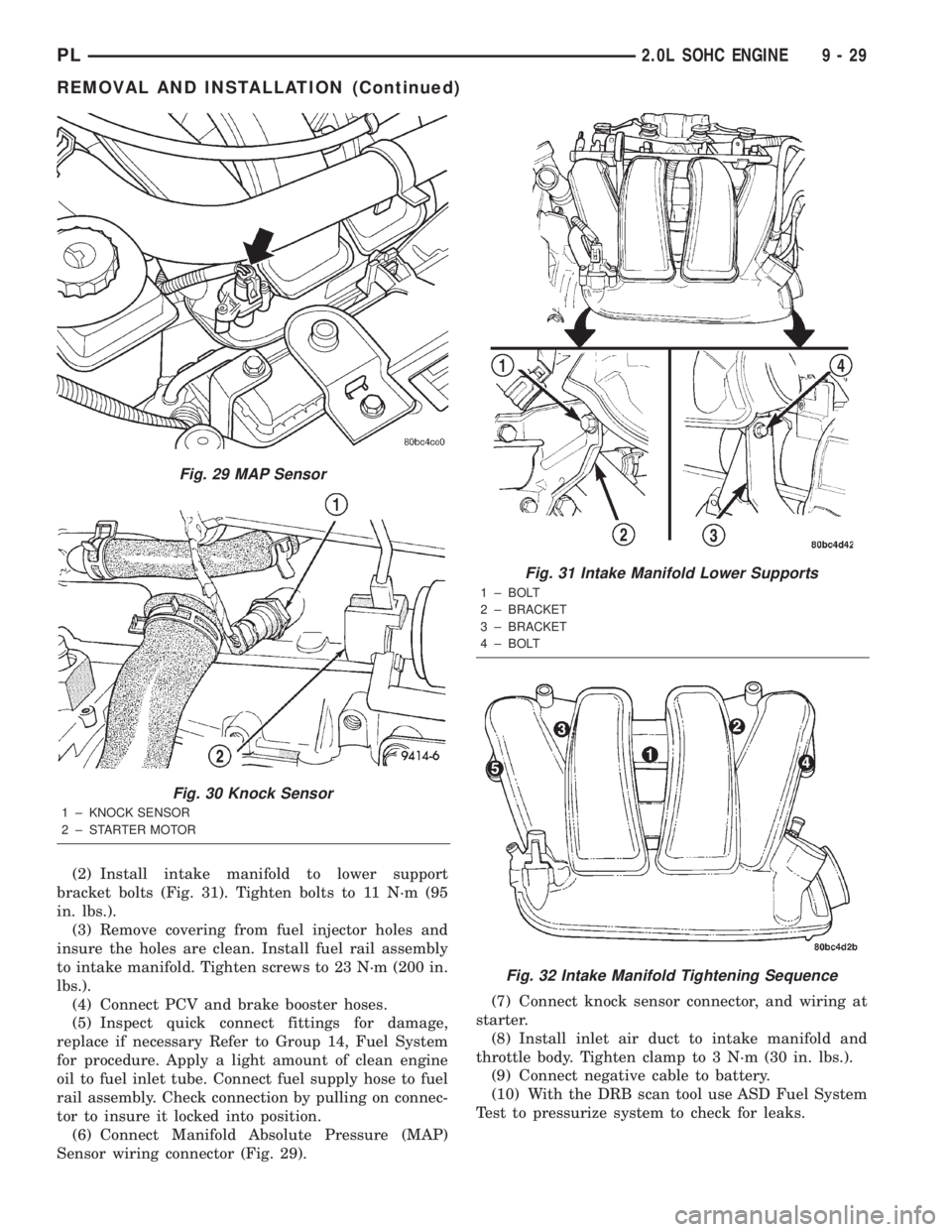
(2) Install intake manifold to lower support
bracket bolts (Fig. 31). Tighten bolts to 11 N´m (95
in. lbs.).
(3) Remove covering from fuel injector holes and
insure the holes are clean. Install fuel rail assembly
to intake manifold. Tighten screws to 23 N´m (200 in.
lbs.).
(4) Connect PCV and brake booster hoses.
(5) Inspect quick connect fittings for damage,
replace if necessary Refer to Group 14, Fuel System
for procedure. Apply a light amount of clean engine
oil to fuel inlet tube. Connect fuel supply hose to fuel
rail assembly. Check connection by pulling on connec-
tor to insure it locked into position.
(6) Connect Manifold Absolute Pressure (MAP)
Sensor wiring connector (Fig. 29).(7) Connect knock sensor connector, and wiring at
starter.
(8) Install inlet air duct to intake manifold and
throttle body. Tighten clamp to 3 N´m (30 in. lbs.).
(9) Connect negative cable to battery.
(10) With the DRB scan tool use ASD Fuel System
Test to pressurize system to check for leaks.
Fig. 29 MAP Sensor
Fig. 30 Knock Sensor
1 ± KNOCK SENSOR
2 ± STARTER MOTOR
Fig. 31 Intake Manifold Lower Supports
1 ± BOLT
2 ± BRACKET
3 ± BRACKET
4 ± BOLT
Fig. 32 Intake Manifold Tightening Sequence
PL2.0L SOHC ENGINE 9 - 29
REMOVAL AND INSTALLATION (Continued)
Page 842 of 1285
FUEL INJECTION SYSTEM
TABLE OF CONTENTS
page page
DESCRIPTION AND OPERATION
INJECTION SYSTEM......................22
MODES OF OPERATION...................22
SYSTEM DIAGNOSIS......................24
POWER DISTRIBUTION CENTER............24
POWERTRAIN CONTROL MODULE...........24
PCM GROUND...........................26
5 VOLT SUPPLYÐPCM OUTPUT.............26
8-VOLT SUPPLYÐPCM OUTPUT.............26
FUEL CORRECTION or ADAPTIVE MEMORIES . . 26
PROGRAMMABLE COMMUNICATIONS
INTERFACE (PCI) BUS...................27
AIR CONDITIONING PRESSURE
TRANSDUCERÐPCM INPUT..............27
AUTOMATIC SHUTDOWN (ASD) SENSEÐ
PCM INPUT...........................27
BATTERY VOLTAGEÐPCM INPUT............28
BRAKE SWITCHÐPCM INPUT...............28
CAMSHAFT POSITION SENSORÐPCM INPUT . . 28
CLUTCH INTERLOCK/UPSTOP SWITCH.......29
CRANKSHAFT POSITION SENSORÐPCM
INPUT................................30
ENGINE COOLANT TEMPERATURE
SENSORÐPCM INPUT...................30
FUEL LEVEL SENSORÐPCM INPUT..........31
HEATED OXYGEN SENSOR (O2 SENSOR)Ð
PCM INPUT...........................32
IGNITION CIRCUIT SENSEÐPCM INPUT......34
INLET AIR TEMPERATURE SENSORÐPCM
INPUT................................34
KNOCK SENSORÐPCM INPUT..............34
MANIFOLD ABSOLUTE PRESSURE (MAP)
SENSORÐPCM INPUT...................35
POWER STEERING PRESSURE SWITCHÐ
PCM INPUT...........................35
SENSOR RETURNÐPCM INPUT.............35
SPEED CONTROLÐPCM INPUT.............36
SCI RECEIVEÐPCM INPUT.................36
PARK/NEUTRAL POSITION SWITCHÐPCM
INPUT................................36
THROTTLE POSITION SENSORÐPCM INPUT . . 36VEHICLE SPEED SIGNAL (VSS)ÐPCM INPUT . . 37
AIR CONDITIONING CLUTCH RELAYÐPCM
OUTPUT..............................38
AUTOMATIC SHUTDOWN RELAYÐPCM
OUTPUT..............................38
CHARGING SYSTEM INDICATOR LAMPÐPCM
OUTPUT..............................38
FUEL PUMP RELAYÐPCM OUTPUT..........38
PROPORTIONAL PURGE SOLENOIDÐPCM
OUTPUT..............................39
GENERATOR FIELDÐPCM OUTPUT..........39
IDLE AIR CONTROL MOTORÐPCM OUTPUT . . . 39
DATA LINK CONNECTOR...................40
FUEL INJECTORSÐPCM OUTPUT...........40
IGNITION COILÐPCM OUTPUT..............40
MALFUNCTION INDICATOR (CHECK ENGINE)
LAMPÐPCM OUTPUT...................41
SPEED CONTROLÐPCM INPUT.............41
SCI RECEIVEÐPCM OUTPUT...............41
TACHOMETERÐPCM OUTPUT..............42
TORQUE CONVERTOR CLUTCH SOLENOIDÐ
PCM OUTPUT..........................42
REMOVAL AND INSTALLATION
THROTTLE BODY........................42
THROTTLE POSITION SENSOR.............43
IDLE AIR CONTROL MOTOR................43
MAP SENSOR...........................44
POWERTRAIN CONTROL MODULE (PCM).....44
UPSTREAM HEATED OXYGEN SENSOR......45
DOWNSTREAM HEATED OXYGEN SENSOR
1/2 ..................................46
AIR CLEANER BOX.......................46
AIR CLEANER ELEMENT...................47
ENGINE COOLANT TEMPERATURE SENSOR . . . 47
VEHICLE SPEED SENSOR.................47
KNOCK SENSOR.........................48
SPECIFICATIONS
VECI LABEL.............................49
TORQUE...............................49
SPECIAL TOOLS
FUEL..................................49
PLFUEL SYSTEM 14 - 21