2000 DODGE NEON brake sensor
[x] Cancel search: brake sensorPage 88 of 1285
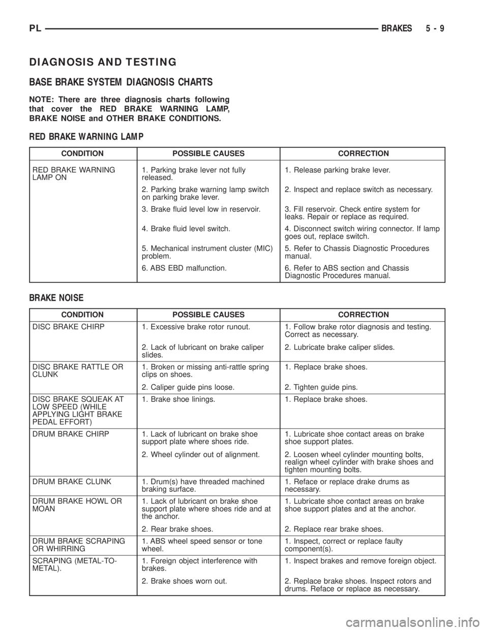
DIAGNOSIS AND TESTING
BASE BRAKE SYSTEM DIAGNOSIS CHARTS
NOTE: There are three diagnosis charts following
that cover the RED BRAKE WARNING LAMP,
BRAKE NOISE and OTHER BRAKE CONDITIONS.
RED BRAKE WARNING LAMP
CONDITION POSSIBLE CAUSES CORRECTION
RED BRAKE WARNING
LAMP ON1. Parking brake lever not fully
released.1. Release parking brake lever.
2. Parking brake warning lamp switch
on parking brake lever.2. Inspect and replace switch as necessary.
3. Brake fluid level low in reservoir. 3. Fill reservoir. Check entire system for
leaks. Repair or replace as required.
4. Brake fluid level switch. 4. Disconnect switch wiring connector. If lamp
goes out, replace switch.
5. Mechanical instrument cluster (MIC)
problem.5. Refer to Chassis Diagnostic Procedures
manual.
6. ABS EBD malfunction. 6. Refer to ABS section and Chassis
Diagnostic Procedures manual.
BRAKE NOISE
CONDITION POSSIBLE CAUSES CORRECTION
DISC BRAKE CHIRP 1. Excessive brake rotor runout. 1. Follow brake rotor diagnosis and testing.
Correct as necessary.
2. Lack of lubricant on brake caliper
slides.2. Lubricate brake caliper slides.
DISC BRAKE RATTLE OR
CLUNK1. Broken or missing anti-rattle spring
clips on shoes.1. Replace brake shoes.
2. Caliper guide pins loose. 2. Tighten guide pins.
DISC BRAKE SQUEAK AT
LOW SPEED (WHILE
APPLYING LIGHT BRAKE
PEDAL EFFORT)1. Brake shoe linings. 1. Replace brake shoes.
DRUM BRAKE CHIRP 1. Lack of lubricant on brake shoe
support plate where shoes ride.1. Lubricate shoe contact areas on brake
shoe support plates.
2. Wheel cylinder out of alignment. 2. Loosen wheel cylinder mounting bolts,
realign wheel cylinder with brake shoes and
tighten mounting bolts.
DRUM BRAKE CLUNK 1. Drum(s) have threaded machined
braking surface.1. Reface or replace drake drums as
necessary.
DRUM BRAKE HOWL OR
MOAN1. Lack of lubricant on brake shoe
support plate where shoes ride and at
the anchor.1. Lubricate shoe contact areas on brake
shoe support plates and at the anchor.
2. Rear brake shoes. 2. Replace rear brake shoes.
DRUM BRAKE SCRAPING
OR WHIRRING1. ABS wheel speed sensor or tone
wheel.1. Inspect, correct or replace faulty
component(s).
SCRAPING (METAL-TO-
METAL).1. Foreign object interference with
brakes.1. Inspect brakes and remove foreign object.
2. Brake shoes worn out. 2. Replace brake shoes. Inspect rotors and
drums. Reface or replace as necessary.
PLBRAKES 5 - 9
Page 109 of 1285
(4) Fill the reservoir with fresh clean DOT 3 brake
fluid. Refer to BRAKE FLUID LEVEL CHECKING
in the SERVICE PROCEDURES section in this sec-
tion of this service manual group.
BRAKE FLUID LEVEL SWITCH
NOTE: Before proceeding with this procedure,
review SERVICE WARNINGS AND CAUTIONS at the
beginning of REMOVAL AND INSTALLATION in this
section.
REMOVAL
(1) Remove the vehicle wiring harness connector
from brake fluid level switch in master cylinder
brake fluid reservoir (Fig. 44).
(2) Push together the retaining tabs holding the
brake fluid level switch in place in the brake fluid
reservoir (Fig. 46).
(3) Pull the brake fluid level switch out the other
side of the reservoir.
INSTALLATION
(1) Align the brake fluid level switch with its
mounting hole on the left side of the master cylinder
brake fluid reservoir. Push the switch into the fluid
reservoir until the switch retaining tabs are
expanded on the other side of the reservoir, locking it
in place (Fig. 46).
(2) Connect the brake fluid level switch wiring
connector (Fig. 44).
POWER BRAKE BOOSTER
NOTE: Before proceeding with this procedure,
review SERVICE WARNINGS AND CAUTIONS at the
beginning of REMOVAL AND INSTALLATION in this
section.
REMOVAL
(1) Disconnect negative (ground) cable from the
battery and isolate the cable.
(2) Disconnect the positive cable from the battery,
then remove the battery from the battery tray. There
is one nut securing the clamp on the backside of the
battery holding it in place.
(3) Remove the one nut and one bolt securing the
air cleaner box in place, then disconnect the wiring
harness connector at the air inlet sensor.
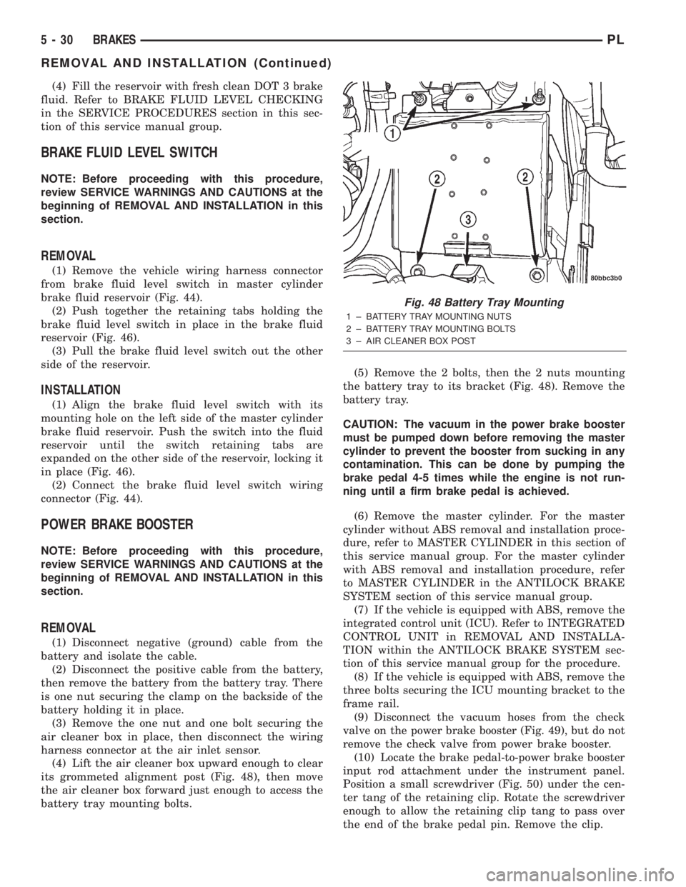
(4) Lift the air cleaner box upward enough to clear
its grommeted alignment post (Fig. 48), then move
the air cleaner box forward just enough to access the
battery tray mounting bolts.(5) Remove the 2 bolts, then the 2 nuts mounting
the battery tray to its bracket (Fig. 48). Remove the
battery tray.
CAUTION: The vacuum in the power brake booster
must be pumped down before removing the master
cylinder to prevent the booster from sucking in any
contamination. This can be done by pumping the
brake pedal 4-5 times while the engine is not run-
ning until a firm brake pedal is achieved.
(6) Remove the master cylinder. For the master
cylinder without ABS removal and installation proce-
dure, refer to MASTER CYLINDER in this section of
this service manual group. For the master cylinder
with ABS removal and installation procedure, refer
to MASTER CYLINDER in the ANTILOCK BRAKE
SYSTEM section of this service manual group.
(7) If the vehicle is equipped with ABS, remove the
integrated control unit (ICU). Refer to INTEGRATED
CONTROL UNIT in REMOVAL AND INSTALLA-
TION within the ANTILOCK BRAKE SYSTEM sec-
tion of this service manual group for the procedure.
(8) If the vehicle is equipped with ABS, remove the
three bolts securing the ICU mounting bracket to the
frame rail.
(9) Disconnect the vacuum hoses from the check
valve on the power brake booster (Fig. 49), but do not
remove the check valve from power brake booster.
(10) Locate the brake pedal-to-power brake booster
input rod attachment under the instrument panel.
Position a small screwdriver (Fig. 50) under the cen-
ter tang of the retaining clip. Rotate the screwdriver
enough to allow the retaining clip tang to pass over
the end of the brake pedal pin. Remove the clip.
Fig. 48 Battery Tray Mounting
1 ± BATTERY TRAY MOUNTING NUTS
2 ± BATTERY TRAY MOUNTING BOLTS
3 ± AIR CLEANER BOX POST
5 - 30 BRAKESPL
REMOVAL AND INSTALLATION (Continued)
Page 111 of 1285
CAUTION: Use only a new brake booster input rod-
to-brake pedal retaining clip to ensure proper
retainment.
(4) Connect the power brake booster input rod-to-
brake pedal pin. Install a new retaining clip. Do not
use the old clip.
(5) Connect all previously removed vacuum hoses
to the vacuum check valve (Fig. 49).
(6) If the vehicle is equipped with ABS, install the
ICU mounting bracket on the frame rail using its
three bolts. Tighten the nuts to a torque of 23 N´m
(200 in. lbs.).
(7) If the vehicle is equipped with ABS, reinstall
the ICU. Refer to INTEGRATED CONTROL UNIT in
REMOVAL AND INSTALLATION within the
ANTILOCK BRAKE SYSTEM section of this service
manual group for the procedure.
(8) Install the master cylinder. For the master cyl-
inder without ABS removal and installation proce-
dure, refer to MASTER CYLINDER in this section of
this service manual group. For the master cylinder
with ABS removal and installation procedure, refer
to MASTER CYLINDER in the ANTILOCK BRAKE
SYSTEM section of this service manual group.
(9) Position the battery tray back in place. Install
the two bolts, then the two nuts mounting the bat-
tery tray to its bracket (Fig. 48). Tighten the two
bolts and nuts to a torque of 34 N´m (25 ft. lbs.).
(10) Reinstall the air cleaner box onto its grom-
meted alignment post (Fig. 48).
(11) Install the one nut and one bolt securing the
air cleaner box in place, then connect the wiring har-
ness connector at the air inlet sensor.
(12) Install the battery and clamp it in place.
(13) Connect the positive, then the negative
(ground) cable on the battery.
(14) Adjust the stop lamp switch as necessary.
Refer to STOP LAMP SWITCH in the ADJUST-
MENTS section of this group.
(15) Bleed the base brake system.
(16) Road test the vehicle to ensure proper opera-
tion of the brakes.
PROPORTIONING VALVE
NOTE: Before proceeding with this procedure,
review SERVICE WARNINGS AND CAUTIONS at the
beginning of REMOVAL AND INSTALLATION in this
section.
REMOVAL
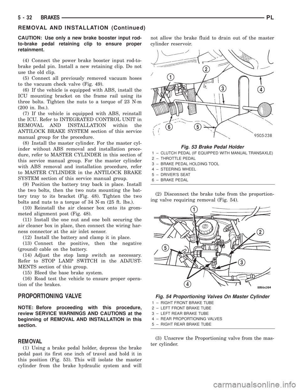
(1) Using a brake pedal holder, depress the brake
pedal past its first one inch of travel and hold it in
this position (Fig. 53). This will isolate the master
cylinder from the brake hydraulic system and willnot allow the brake fluid to drain out of the master
cylinder reservoir.
(2) Disconnect the brake tube from the proportion-
ing valve requiring removal (Fig. 54).
(3) Unscrew the Proportioning valve from the mas-
ter cylinder.
Fig. 53 Brake Pedal Holder
1 ± CLUTCH PEDAL (IF EQUIPPED WITH MANUAL TRANSAXLE)
2 ± THROTTLE PEDAL
3 ± BRAKE PEDAL HOLDING TOOL
4 ± STEERING WHEEL
5 ± DRIVER'S SEAT
6 ± BRAKE PEDAL
Fig. 54 Proportioning Valves On Master Cylinder
1 ± RIGHT FRONT BRAKE TUBE
2 ± LEFT FRONT BRAKE TUBE
3 ± LEFT REAR BRAKE TUBE
4 ± REAR PROPORTIONING VALVES
5 ± RIGHT REAR BRAKE TUBE
5 - 32 BRAKESPL
REMOVAL AND INSTALLATION (Continued)
Page 142 of 1285
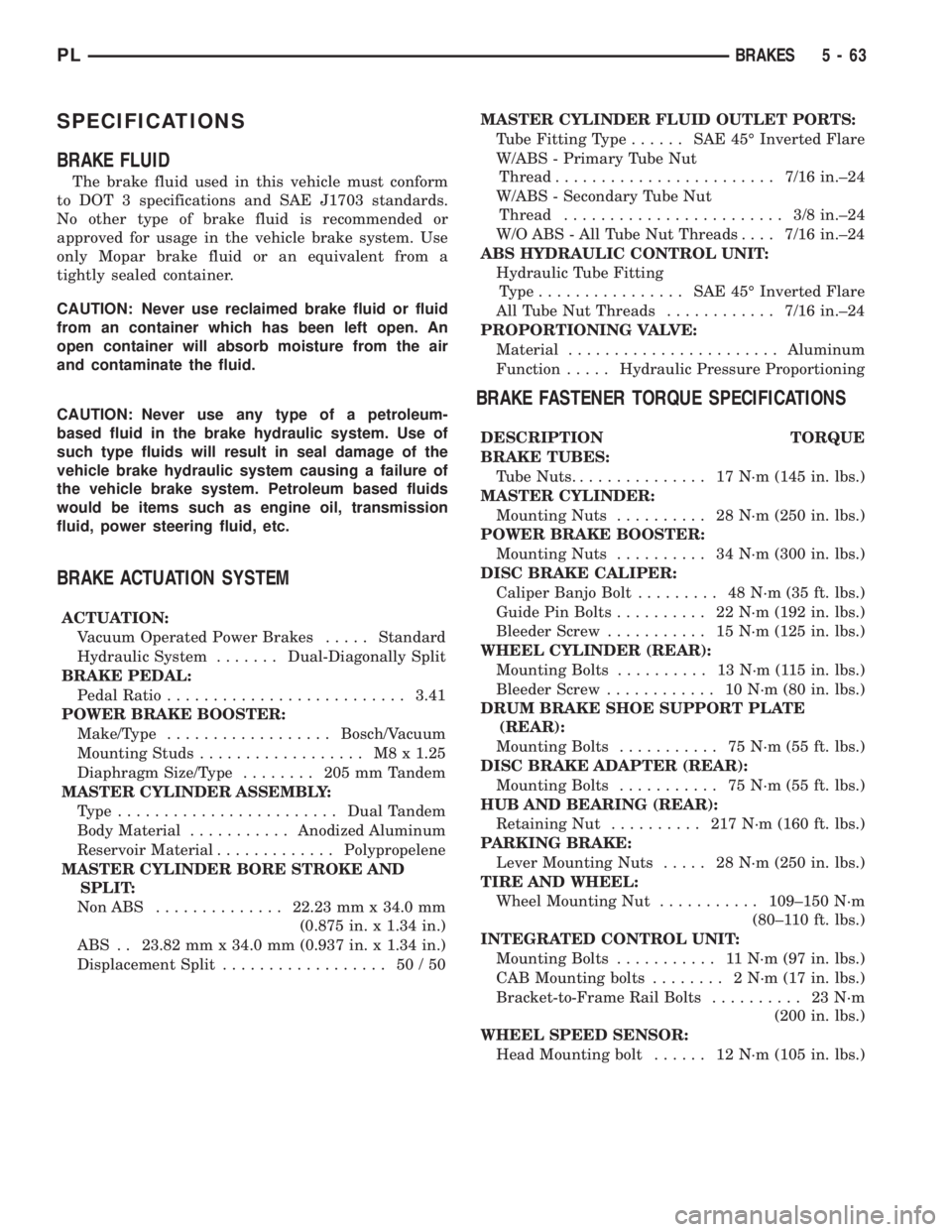
SPECIFICATIONS
BRAKE FLUID
The brake fluid used in this vehicle must conform
to DOT 3 specifications and SAE J1703 standards.
No other type of brake fluid is recommended or
approved for usage in the vehicle brake system. Use
only Mopar brake fluid or an equivalent from a
tightly sealed container.
CAUTION: Never use reclaimed brake fluid or fluid
from an container which has been left open. An
open container will absorb moisture from the air
and contaminate the fluid.
CAUTION: Never use any type of a petroleum-
based fluid in the brake hydraulic system. Use of
such type fluids will result in seal damage of the
vehicle brake hydraulic system causing a failure of
the vehicle brake system. Petroleum based fluids
would be items such as engine oil, transmission
fluid, power steering fluid, etc.
BRAKE ACTUATION SYSTEM
ACTUATION:
Vacuum Operated Power Brakes.....Standard
Hydraulic System.......Dual-Diagonally Split
BRAKE PEDAL:
Pedal Ratio..........................3.41
POWER BRAKE BOOSTER:
Make/Type..................Bosch/Vacuum
Mounting Studs.................. M8x1.25
Diaphragm Size/Type........ 205mmTandem
MASTER CYLINDER ASSEMBLY:
Type ........................Dual Tandem
Body Material...........Anodized Aluminum
Reservoir Material.............Polypropelene
MASTER CYLINDER BORE STROKE AND
SPLIT:
NonABS ..............22.23 mm x 34.0 mm
(0.875 in. x 1.34 in.)
ABS . . 23.82 mm x 34.0 mm (0.937 in. x 1.34 in.)
Displacement Split.................. 50/50MASTER CYLINDER FLUID OUTLET PORTS:
Tube Fitting Type...... SAE45ÉInverted Flare
W/ABS - Primary Tube Nut
Thread........................7/16 in.±24
W/ABS - Secondary Tube Nut
Thread........................ 3/8in.±24
W/O ABS - All Tube Nut Threads....7/16 in.±24
ABS HYDRAULIC CONTROL UNIT:
Hydraulic Tube Fitting
Type................ SAE45ÉInverted Flare
All Tube Nut Threads............7/16 in.±24
PROPORTIONING VALVE:
Material.......................Aluminum
Function.....Hydraulic Pressure Proportioning
BRAKE FASTENER TORQUE SPECIFICATIONS
DESCRIPTION TORQUE
BRAKE TUBES:
Tube Nuts............... 17N´m(145 in. lbs.)
MASTER CYLINDER:
Mounting Nuts.......... 28N´m(250 in. lbs.)
POWER BRAKE BOOSTER:
Mounting Nuts.......... 34N´m(300 in. lbs.)
DISC BRAKE CALIPER:
Caliper Banjo Bolt......... 48N´m(35ft.lbs.)
Guide Pin Bolts.......... 22N´m(192 in. lbs.)
Bleeder Screw........... 15N´m(125 in. lbs.)
WHEEL CYLINDER (REAR):
Mounting Bolts.......... 13N´m(115in.lbs.)
Bleeder Screw............ 10N´m(80in.lbs.)
DRUM BRAKE SHOE SUPPORT PLATE
(REAR):
Mounting Bolts........... 75N´m(55ft.lbs.)
DISC BRAKE ADAPTER (REAR):
Mounting Bolts........... 75N´m(55ft.lbs.)
HUB AND BEARING (REAR):
Retaining Nut.......... 217N´m(160 ft. lbs.)
PARKING BRAKE:
Lever Mounting Nuts..... 28N´m(250 in. lbs.)
TIRE AND WHEEL:
Wheel Mounting Nut...........109±150 N´m
(80±110 ft. lbs.)
INTEGRATED CONTROL UNIT:
Mounting Bolts........... 11N´m(97in.lbs.)
CAB Mounting bolts........ 2N´m(17in.lbs.)
Bracket-to-Frame Rail Bolts.......... 23N´m
(200 in. lbs.)
WHEEL SPEED SENSOR:
Head Mounting bolt...... 12N´m(105 in. lbs.)
PLBRAKES 5 - 63
Page 144 of 1285
ANTILOCK BRAKE SYSTEM
TABLE OF CONTENTS
page page
DESCRIPTION AND OPERATION
ANTILOCK BRAKE SYSTEM OPERATION......65
ANTILOCK BRAKE SYSTEM COMPONENTS....66
ELECTRONIC BRAKE DISTRIBUTION.........69
TRACTION CONTROL SYSTEM..............70
HYDRAULIC CIRCUITS AND VALVE
OPERATION...........................71
DIAGNOSIS AND TESTING
SERVICE WARNINGS AND CAUTIONS........74
ABS GENERAL DIAGNOSTICS INFORMATION . . 74
ABS WIRING DIAGRAM INFORMATION........74
ABS VEHICLE TEST DRIVE.................74
ABS ELECTRONIC DIAGNOSIS..............75
TONE WHEEL...........................76
BRAKE FLUID CONTAMINATION.............76
SERVICE PROCEDURES
BRAKE FLUID LEVEL CHECKING............77ANTILOCK BRAKE SYSTEM BLEEDING.......77
MASTER CYLINDER BLEEDING.............77
REMOVAL AND INSTALLATION
SERVICE WARNINGS AND CAUTIONS........78
MASTER CYLINDER......................78
INTEGRATED CONTROL UNIT...............79
WHEEL SPEED SENSOR (FRONT)...........81
WHEEL SPEED SENSOR (REAR)............83
DISASSEMBLY AND ASSEMBLY
INTEGRATED CONTROL UNIT...............84
SPECIFICATIONS
TONE WHEEL RUNOUT....................85
WHEEL SPEED SENSOR-TO-TONE WHEEL
CLEARANCE...........................85
BRAKE FASTENER TORQUE
SPECIFICATIONS.......................85
DESCRIPTION AND OPERATION
ANTILOCK BRAKE SYSTEM OPERATION
This section covers the physical and operational
descriptions, and the on-car service procedures for
the Mark 20e Antilock Brake System (ABS) with
traction control. It is the only antilock brake system
available on this vehicle.
The purpose of the antilock brake system is to pre-
vent wheel lockup under braking conditions on virtu-
ally any type of road surface. Antilock braking is
desirable because a vehicle that is stopped without
locking the wheels retains directional stability and
some steering capability. This allows the driver to
retain greater control of the vehicle during braking.
The traction control system reduces wheel slip and
maintains traction at the driving speeds below 56
kph (35 mph) when road conditions call for traction
assistance. Refer to TRACTION CONTROL SYSTEM
in this section for more information.
Vehicles equipped with ABS use electronic brake
distribution (EBD) to balance front-to-rear braking
when the brakes are applied in the partial braking
range. Refer to ELECTRONIC BRAKE DISTRIBU-
TION in this section for more information.
There are a few performance characteristics of the
Mark 20e Antilock Brake System that may at first
seem abnormal, but in fact are normal. These char-
acteristics are described below.
NORMAL BRAKING
Under normal braking conditions, the ABS func-
tions the same as a standard base brake system with
a diagonally split master cylinder and conventional
vacuum assist.
ABS BRAKING
ABS operation is available at all vehicle speeds
above 3±5 mph. If a wheel locking tendency is
detected during a brake application, the brake sys-
tem enters the ABS mode. During ABS braking,
hydraulic pressure in the four wheel circuits is mod-
ulated to prevent any wheel from locking. Each
wheel circuit is designed with a set of electric sole-
noids to allow modulation, although for vehicle sta-
bility, both rear wheel solenoids receive the same
electrical signal. Wheel lockup may be perceived at
the very end of an ABS stop and is considered nor-
mal.
During an ABS stop, the brakes hydraulic system
is still diagonally split. However, the brake system
pressure is further split into four control channels.
During antilock operation of the vehicle's brake sys-
tem, the wheels are controlled independently and are
on separate control channels.
The system can build, hold and release pressure at
each wheel, depending on signals generated by the
wheel speed sensors (WSS) at each wheel and
received at the controller antilock brake (CAB).
PLBRAKES 5 - 65
Page 145 of 1285
NOISE AND BRAKE PEDAL FEEL
During ABS braking, some brake pedal movement
may be felt. In addition, ABS braking will create
ticking, popping, or groaning noises heard by the
driver. This is normal and is due to pressurized fluid
being transferred between the master cylinder and
the brakes. If ABS operation occurs during hard
braking, some pulsation may be felt in the vehicle
body due to fore-and-aft movement of the suspension
as brake pressures are modulated.
At the end of an ABS stop, ABS is turned off when
the vehicle is slowed to a speed of 3±4 mph. There
may be a slight brake pedal drop anytime that the
ABS is deactivated, such as at the end of the stop
when the vehicle speed is less than 3 mph or during
an ABS stop where ABS is no longer required. These
conditions exist when a vehicle is being stopped on a
road surface with patches of ice, loose gravel, or sand
on it. Also, stopping a vehicle on a bumpy road sur-
face activates ABS because of the wheel hop caused
by the bumps.
TIRE NOISE AND MARKS
Although the ABS system prevents complete wheel
lockup, some wheel slip is desired in order to achieve
optimum braking performance. Wheel slip is defined
as follows: 0 percent slip means the wheel is rolling
freely and 100 percent slip means the wheel is fully
locked. During brake pressure modulation, wheel slip
is allowed to reach up to 25±30 percent. This means
that the wheel rolling velocity is 25±30 percent less
than that of a free rolling wheel at a given vehicle
speed. This slip may result in some tire chirping,
depending on the road surface. This sound should not
be interpreted as total wheel lockup.
Complete wheel lockup normally leaves black tire
marks on dry pavement. The ABS will not leave dark
black tire marks since the wheel never reaches a
fully locked condition. However, tire marks may be
noticeable as light patched marks.
START-UP CYCLE
When the ignition is turned on, a popping sound
and a slight brake pedal movement may be noticed.
The ABS warning lamp will also be on for up to 5
seconds after the ignition is turned on. When the
vehicle is first driven off, a humming may be heard
or felt by the driver at approximately 20±40 kph
(12±25 mph). All of these conditions are a normal
function of ABS as the system is performing a diag-
nosis check.
PREMATURE ABS CYCLING
Symptoms of premature ABS cycling include: click-
ing sounds from the solenoid valves; pump/motor
running; and pulsations in the brake pedal. Prema-ture ABS cycling can occur at any braking rate of the
vehicle and on any type of road surface. Neither the
red BRAKE warning lamp, nor the amber ABS warn-
ing lamp, illuminate and no fault codes are stored in
the CAB.
Premature ABS cycling is a condition that needs to
be correctly assessed when diagnosing problems with
the antilock brake system. It may be necessary to use
a DRB scan tool to detect and verify premature ABS
cycling.
Check the following common causes when diagnos-
ing premature ABS cycling: damaged tone wheels;
incorrect tone wheels; damaged steering knuckle
wheel speed sensor mounting bosses; loose wheel
speed sensor mounting bolts; excessive tone wheel
runout; or an excessively large tone wheel-to-wheel
speed sensor air gap. Give special attention to these
components when diagnosing a vehicle exhibiting
premature ABS cycling.
After diagnosing the defective component, repair or
replace it as required. When the component repair or
replacement is completed, test drive the vehicle to
verify that premature ABS cycling has been cor-
rected.
ANTILOCK BRAKE SYSTEM COMPONENTS
The following is a detailed description of the
antilock brake system components. For information
on servicing base brake system components used in
conjunction with these components, see the BASE
BRAKE SYSTEM found at the beginning of this ser-
vice manual group.
MASTER CYLINDER
A vehicle equipped with ABS uses a different mas-
ter cylinder than a vehicle that is not equipped with
ABS. Vehicles equipped with ABS use a center port
master cylinder with only two outlet ports (Fig. 1).
The brake tubes from the primary and secondary
outlet ports on the master cylinder go directly to the
integrated control unit (ICU).
The master cylinder mounts to the power brake
booster in the same manner a non-ABS master cylin-
der does.
INTEGRATED CONTROL UNIT (ICU)
The hydraulic control unit (HCU) and the control-
ler antilock brake (CAB) used with this antilock
brake system are combined (integrated) into one
unit, which is called the integrated control unit (ICU)
(Fig. 2). The ICU is located on the driver's side of the
vehicle, and is mounted to the left front frame rail
below the master cylinder (Fig. 1).
5 - 66 BRAKESPL
DESCRIPTION AND OPERATION (Continued)
Page 146 of 1285
The ABS with traction control ICU consists of the
following components: the CAB, eight (build/decay)
solenoid valves (four inlet valves and four outlet
valves), two hydraulic shuttle valves, two traction
control valves, valve block, fluid accumulators, a
pump, and an electric pump/motor.
The replaceable components of the ICU are the
HCU and the CAB. No attempt should be made to
service any components found inside of the HCU or
CAB.
CONTROLLER ANTILOCK BRAKE (CAB)
The controller antilock brake (CAB) is a micropro-
cessor-based device which monitors the ABS system
during normal braking and controls it when the vehi-
cle is in an ABS stop. The CAB is mounted to the
bottom of the HCU (Fig. 2). The CAB uses a 25-way
electrical connector on the vehicle wiring harness.
The power source for the CAB is through the ignition
switch in the RUN or ON position. The CAB is on
the PCI bus.
The primary functions of the (CAB) are to:
(1) monitor the antilock brake system for proper
operation.
(2) detect wheel locking or wheel slipping tenden-
cies by monitoring the speed of all four wheels of the
vehicle.
(3) control fluid modulation to the wheel brakes
while the system is in an ABS mode or the traction
control system is activated.
(4) store diagnostic information.
(5) provide communication to the DRB scan tool
while in diagnostic mode.
The CAB constantly monitors the antilock brake
system for proper operation. If the CAB detects a
fault, it will send a message to the mechanical instu-
ment cluster (MIC) instructing it to turn on the
amber ABS warning lamp and disable the antilock
braking system. The normal base braking system will
remain operational.
The CAB continuously monitors the speed of each
wheel through the signals generated by the wheel
speed sensors to determine if any wheel is beginning
to lock. When a wheel locking tendency is detected,
the CAB commands the CAB command coils to actu-
ate. The CAB command coils then open and close the
valves in the HCU that modulate brake fluid pres-
sure in some or all of the hydraulic circuits. The CAB
continues to control pressure in individual hydraulic
circuits until a locking tendency is no longer present.
The CAB contains a self-diagnostic program that
monitors the antilock brake system for system faults.
When a fault is detected, the amber ABS warning
lamp is turned on and the fault diagnostic trouble
code (DTC) is then stored in a diagnostic program
memory. These DTC's will remain in the CAB mem-
ory even after the ignition has been turned off. The
DTC's can be read and cleared from the CAB mem-
ory by a technician using the DRB scan tool. If not
cleared with a DRB scan tool, the fault occurrence
and DTC will be automatically cleared from the CAB
memory after the identical fault has not been seen
during the next 3,500 miles of vehicle operation.
Fig. 1 Master Cylinder And ICU
1 ± PRIMARY BRAKE TUBE
2 ± MASTER CYLINDER
3 ± SECONDARY BRAKE TUBE
4 ± ABS ICU
Fig. 2 Integrated Control Unit (ICU)
1 ± HCU
2 ± PUMP/MOTOR
3 ± CAB
PLBRAKES 5 - 67
DESCRIPTION AND OPERATION (Continued)
Page 147 of 1285
CONTROLLER ANTILOCK BRAKE INPUTS
²wheel speed sensors (four)
²stop lamp switch
²ignition switch
²system relay voltage
²ground
²traction control lamp
²diagnostic communication (PCI)
CONTROLLER ANTILOCK BRAKE OUTPUTS
²amber ABS warning lamp actuation (through
MIC)
²red BRAKE warning lamp actuation (through
MIC)
²traction control lamp actuation (through MIC)
²diagnostic communication. (PCI)
HYDRAULIC CONTROL UNIT (HCU)
The hydraulic control unit (HCU) is mounted to
the CAB as part of the ICU (Fig. 2). The HCU con-
trols the flow of brake fluid to the brakes using a
series of valves and accumulators. A pump/motor is
mounted on the HCU to supply build pressure to the
brakes during an ABS stop.
VALVES AND SOLENOIDS
The valve block contains four inlet valves and four
outlet solenoid valves. The inlet valves are spring-
loaded in the open position and the outlet valves are
spring-loaded in the closed position during normal
braking. The fluid is allowed to flow from the master
cylinder to the wheel brakes.
During an ABS stop, these valves cycle to maintain
the proper slip ratio for each wheel. The inlet valve
closes preventing further pressure increase and the
outlet valve opens to provide a path from the wheel
brake to the HCU accumulators and pump/motor.
This releases (decays) pressure from the wheel brake,
thus releasing the wheel from excessive slippage.
Once the wheel is no longer slipping, the outlet valve
is closed and the inlet valve is opened to reapply
(build) pressure.
There are four other valves in the HCU. These four
remaining valves are used for traction control. Two
traction control (TC) valves, mounted in the HCU
valve block, are normally in the open position and
close only when the traction control is applied. There
are also two shuttle valves which control pressure
return to the master cylinder under ABS and traction
control conditions.
These TC valves are used to isolate the rear (non-
driving) wheels of the vehicle from the hydraulic
pressure that the HCU pump/motor is sending to the
front (driving) wheels when traction control is being
applied. The rear brakes need to be isolated from the
master cylinder when traction control is beingapplied so the rear wheels do not drag. For more
information on the TC and shuttle valves, see TRAC-
TION CONTROL SYSTEM in this section.
BRAKE FLUID ACCUMULATORS
There are two fluid accumulators in the HCU: one
for the primary hydraulic circuit, and one for the sec-
ondary hydraulic circuit. Each hydraulic circuit uses
a 3 cc accumulator.
The fluid accumulators temporarily store brake
fluid that is removed from the wheel brakes during
an ABS cycle. This stored fluid is used by the pump/
motor to provide build pressure for the brake hydrau-
lic system. When the antilock stop is complete, the
accumulators are drained by the pump/motor.
There are two noise dampening chambers in the
HCU on this vehicle equipped with traction control.
PUMP/MOTOR
There are two pump assemblies in the HCU: one
for the primary hydraulic circuit, and one for the sec-
ondary hydraulic circuit. Both pumps are driven by a
common electric motor (Fig. 2). This DC-type motor
is integral to the HCU and is controlled by the CAB.
The pump/motor provides the extra amount of
brake fluid needed during antilock braking. Brake
fluid is released to the accumulators when the outlet
valve is opened during an antilock stop. The pump
mechanism consists of two opposing pistons operated
by an eccentric camshaft. In operation, these pistons
are used to purge fluid from the accumulators back
into the master cylinder circuits. When the antilock
stop is complete, the pump/motor drains the accumu-
lators.
The pump motor is also used to build pressure
when the system goes into traction control mode. For
more information, refer to TRACTION CONTROL
SYSTEM in this section.
The CAB may turn on the pump/motor when an
antilock stop is detected. The pump/motor continues
to run during the antilock stop and is turned off after
the stop is complete. Under some conditions, the
pump/motor runs to drain the accumulators during
the next drive-off.
The pump/motor is not a serviceable item; if it
requires replacement, the HCU must be replaced.
ABS FUSES
The ABS fuse and the ABS pump/motor fuse are
located in the power distribution center (PDC). Refer
to the sticker on the inside of the PDC cover for the
location of these fuses. The PDC is located on the
driver's side of the engine compartment between the
back of the battery and the brake master cylinder.
The CAB fuse can be found in the fuse junction
block under the instrument panel.
5 - 68 BRAKESPL
DESCRIPTION AND OPERATION (Continued)