2000 DODGE NEON key
[x] Cancel search: keyPage 1050 of 1285
BRAKE TRANSMISSION SHIFT INTERLOCK
SYSTEM
VERIFICATION
The following chart describes the normal operation
of the Brake Transmission Shift Interlock (BTSI) sys-
tem. If the ªexpected responseº differs from the vehi-
cle's response, then system repair and/or adjustment
is necessary.
ADJUSTMENT
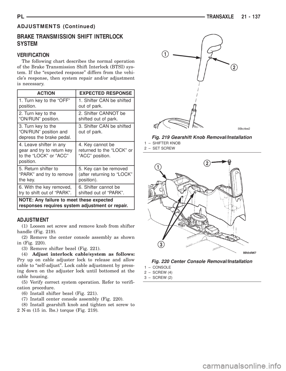
(1) Loosen set screw and remove knob from shifter
handle (Fig. 219).
(2) Remove the center console assembly as shown
in (Fig. 220).
(3) Remove shifter bezel (Fig. 221).
(4)Adjust interlock cable/system as follows:
Pry up on cable adjuster lock to release and allow
cable to ªself-adjustº. Lock cable adjustment by press-
ing down on the adjuster lock until bottomed at the
cable housing.
(5) Verify correct system operation. Refer to verifi-
cation procedure.
(6) Install shifter bezel (Fig. 221).
(7) Install center console assembly (Fig. 220).
(8) Install gearshift knob and tighten set screw to
2 N´m (15 in. lbs.) torque (Fig. 219).
ACTION EXPECTED RESPONSE
1. Turn key to the ªOFFº
position.1. Shifter CAN be shifted
out of park.
2. Turn key to the
9ON/RUNº position.2. Shifter CANNOT be
shifted out of park.
3. Turn key to the
ªON/RUNº position and
depress the brake pedal.3. Shifter CAN be shifted
out of park.
4. Leave shifter in any
gear and try to return key
to the ªLOCKº or9ACCº
position.4. Key cannot be
returned to the ªLOCKº or
ªACCº position.
5. Return shifter to
ªPARKº and try to remove
the key.5. Key can be removed
(after returning to ªLOCKº
position).
6. With the key removed,
try to shift out of ªPARKº.6. Shifter cannot be
shifted out of ªPARKº.
NOTE: Any failure to meet these expected
responses requires system adjustment or repair.
Fig. 219 Gearshift Knob Removal/Installation
1 ± SHIFTER KNOB
2 ± SET SCREW
Fig. 220 Center Console Removal/Installation
1 ± CONSOLE
2 ± SCREW (4)
3 ± SCREW (2)
PLTRANSAXLE 21 - 137
ADJUSTMENTS (Continued)
Page 1090 of 1285
that may induce an erroneous failure. This prevents
illuminating the MIL for the wrong fault and allows
more precis diagnosis.
For example, if the PCM is storing a one trip fault
for the Oxygen Sensor and the EGR monitor, the
Task Manager may still run the EGR Monitor but
will suspend the results until the Oxygen Sensor
Monitor either passes or fails. At that point the Task
Manager can determine if the EGR system is actu-
ally failing or if an Oxygen Sensor is failing.
MIL Illumination
The PCM Task Manager carries out the illumina-
tion of the MIL. The Task Manager triggers MIL illu-
mination upon test failure, depending on monitor
failure criteria.
The Task Manager Screen shows both a Requested
MIL state and an Actual MIL state. When the MIL is
illuminated upon completion of a test for a third trip,
the Requested MIL state changes to OFF. However,
the MIL remains illuminated until the next key
cycle. (On some vehicles, the MIL will actually turn
OFF during the third key cycle) During the key cycle
for the third good trip, the Requested MIL state is
OFF, while the Actual MILL state is ON. After the
next key cycle, the MIL is not illuminated and both
MIL states read OFF.
Diagnostic Trouble Codes (DTCs)
With OBD II, different DTC faults have different
priorities according to regulations. As a result, the
priorities determine MIL illumination and DTC era-
sure. DTCs are entered according to individual prior-
ity. DTCs with a higher priority overwrite lower
priority DTCs.
Priorities
²Priority 0 ÐNon-emissions related trouble codes
²Priority 1 Ð One trip failure of a two trip fault
for non-fuel system and non-misfire.
²Priority 2 Ð One trip failure of a two trip fault
for fuel system (rich/lean) or misfire.
²Priority3ÐTwotrip failure for a non-fuel sys-
tem and non-misfire or matured one trip comprehen-
sive component fault.
²Priority4ÐTwotrip failure or matured fault
for fuel system (rich/lean) and misfire or one trip cat-
alyst damaging misfire.
Non-emissions related failures have no priority.
One trip failures of two trip faults have low priority.
Two trip failures or matured faults have higher pri-
ority. One and two trip failures of fuel system and
misfire monitor take precedence over non-fuel system
and non-misfire failures.DTC Self Erasure
With one trip components or systems, the MIL is
illuminated upon test failure and DTCs are stored.
Two trip monitors are components requiring failure
in two consecutive trips for MIL illumination. Upon
failure of the first test, the Task Manager enters a
maturing code. If the component fails the test for a
second time the code matures and a DTC is set.
After three good trips the MIL is extinguished and
the Task Manager automatically switches the trip
counter to a warm-up cycle counter. DTCs are auto-
matically erased following 40 warm-up cycles if the
component does not fail again.
For misfire and fuel system monitors, the compo-
nent must pass the test under a Similar Conditions
Window in order to record a good trip. A Similar Con-
ditions Window is when engine RPM is within6375
RPM and load is within610% of when the fault
occurred.
NOTE: It is important to understand that a compo-
nent does not have to fail under a similar window of
operation to mature. It must pass the test under a
Similar Conditions Window when it failed to record
a Good Trip for DTC erasure for misfire and fuel
system monitors.
DTCs can be erased anytime with a DRB III. Eras-
ing the DTC with the DRB III erases all OBD II
information. The DRB III automatically displays a
warning that erasing the DTC will also erase all
OBD II monitor data. This includes all counter infor-
mation for warm-up cycles, trips and Freeze Frame.
Trip Indicator
TheTripis essential for running monitors and
extinguishing the MIL. In OBD II terms, a trip is a
set of vehicle operating conditions that must be met
for a specific monitor to run. All trips begin with a
key cycle.
Good Trip
The Good Trip counters are as follows:
²Global Good Trip
²Fuel System Good Trip
²Misfire Good Trip
²Alternate Good Trip (appears as a Global Good
Trip on DRB III)
²Comprehensive Components
²Major Monitor
²Warm-Up Cycles
Global Good Trip
To increment a Global Good Trip, the Oxygen sen-
sor and Catalyst efficiency monitors must have run
and passed.
Fuel System Good Trip
To count a good trip (three required) and turn off
the MIL, the following conditions must occur:
PLEMISSION CONTROL SYSTEMS 25 - 3
DESCRIPTION AND OPERATION (Continued)
Page 1092 of 1285
MISFIRE
²Same Misfire Warm-Up StateÐ Indicates if
the misfire occurred when the engine was warmed up
(above 160É F).
²In Similar Misfire WindowÐ An indicator
that 'Absolute MAP When Misfire Occurred' and
'RPM When Misfire Occurred' are all in the same
range when the failure occurred. Indicated by switch-
ing from 'NO' to 'YES'.
²Absolute MAP When Misfire OccurredÐ
The stored MAP reading at the time of failure.
Informs the user at what engine load the failure
occurred.
²Absolute MAPÐ A live reading of engine load
to aid the user in accessing the Similar Conditions
Window.
²RPM When Misfire OccurredÐ The stored
RPM reading at the time of failure. Informs the user
at what engine RPM the failure occurred.
²Engine RPMÐ A live reading of engine RPM
to aid the user in accessing the Similar Conditions
Window.
²Adaptive Memory FactorÐ The PCM uti-
lizes both Short Term Compensation and Long Term
Adaptive to calculate the Adaptive Memory Factor
for total fuel correction.
²200 Rev CounterÐ Counts 0±100 720 degree
cycles.
²SCW Cat 200 Rev CounterÐ Counts when in
similar conditions.
²SCW FTP 1000 Rev CounterÐ Counts 0±4
when in similar conditions.
²Misfire Good Trip CounterÐ Counts up to
three to turn OFF the MIL.
MALFUNCTION INDICATOR LAMP (MIL)
OPERATION
As a functional test, the Malfunction Indicator
Lamp (MIL) illuminates at key-on before engine
cranking. Whenever the Powertrain Control Module
(PCM) sets a Diagnostic Trouble Code (DTC) that
affects vehicle emissions, it illuminates the MIL. If a
problem is detected, the PCM sends a message over
the PCI Bus to the instrument cluster to illuminate
the lamp. The PCM illuminates the MIL only for
DTC's that affect vehicle emissions. The MIL stays
on continuously when the PCM has entered a
Limp-In mode or identified a failed emission compo-
nent or system. The MIL remains on until the DTC
is erased. Refer to the Diagnostic Trouble Code
charts in this group for emission related codes.
Also, the MIL either flashes or illuminates contin-
uously when the PCM detects active engine misfire.
Refer to Misfire Monitoring in this section.Additionally, the PCM may reset (turn off) the MIL
when one of the following occur:
²PCM does not detect the malfunction for 3 con-
secutive trips (except misfire and fuel system moni-
tors).
²PCM does not detect a malfunction while per-
forming three successive engine misfire or fuel sys-
tem tests. The PCM performs these tests while the
engine is operating within6375 RPM of and within
10 % of the load of the operating condition at which
the malfunction was first detected.
DRB III STATE DISPLAY TEST MODE
OPERATION
The switch inputs to the Powertrain Control Mod-
ule (PCM) have two recognized states; HIGH and
LOW. For this reason, the PCM cannot recognize the
difference between a selected switch position versus
an open circuit, a short circuit, or a defective switch.
If the State Display screen shows the change from
HIGH to LOW or LOW to HIGH, assume the entire
switch circuit to the PCM functions properly. From
the state display screen, access either State Display
Inputs and Outputs or State Display Sensors.
DRB III CIRCUIT ACTUATION TEST MODE
OPERATION
The Circuit Actuation Test Mode checks for proper
operation of output circuits or devices the Powertrain
Control Module (PCM) may not internally recognize.
The PCM attempts to activate these outputs and
allow an observer to verify proper operation. Most of
the tests provide an audible or visual indication of
device operation (click of relay contacts, fuel spray,
etc.). Except for intermittent conditions, if a device
functions properly during testing, assume the device,
its associated wiring, and driver circuit work cor-
rectly.
DIAGNOSTIC TROUBLE CODES
DESCRIPTION
A Diagnostic Trouble Code (DTC) indicates the
PCM has recognized an abnormal condition in the
system.
Remember that DTC's are the results of a sys-
tem or circuit failure, but do not directly iden-
tify the failed component or components.
NOTE: For a list of DTC's, refer to the charts in this
section.
PLEMISSION CONTROL SYSTEMS 25 - 5
DESCRIPTION AND OPERATION (Continued)
Page 1093 of 1285
OPERATION
BULB CHECK
Each time the ignition key is turned to the ON
position, the malfunction indicator (check engine)
lamp on the instrument panel should illuminate for
approximately 2 seconds then go out. This is done for
a bulb check.
OBTAINING DTC'S USING DRB SCAN TOOL
(1) Connect the DRB scan tool to the data link
(diagnostic) connector. This connector is located inthe passenger compartment; at the lower edge of
instrument panel; near the steering column.
(2) Turn the ignition switch on and access the
ªRead Faultº screen.
(3) Record all the DTC's and ªfreeze frameº infor-
mation shown on the DRB scan tool.
(4) To erase DTC's, use the ªErase Trouble Codeº
data screen on the DRB scan tool.Do not erase any
DTC's until problems have been investigated
and repairs have been performed.
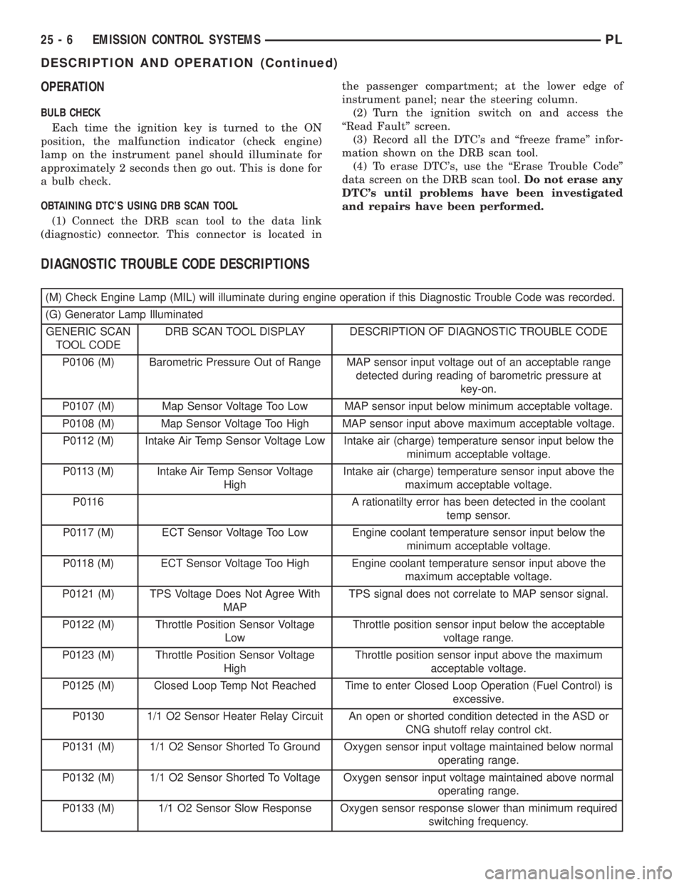
DIAGNOSTIC TROUBLE CODE DESCRIPTIONS
(M) Check Engine Lamp (MIL) will illuminate during engine operation if this Diagnostic Trouble Code was recorded.
(G) Generator Lamp Illuminated
GENERIC SCAN
TOOL CODEDRB SCAN TOOL DISPLAY DESCRIPTION OF DIAGNOSTIC TROUBLE CODE
P0106 (M) Barometric Pressure Out of Range MAP sensor input voltage out of an acceptable range
detected during reading of barometric pressure at
key-on.
P0107 (M) Map Sensor Voltage Too Low MAP sensor input below minimum acceptable voltage.
P0108 (M) Map Sensor Voltage Too High MAP sensor input above maximum acceptable voltage.
P0112 (M) Intake Air Temp Sensor Voltage Low Intake air (charge) temperature sensor input below the
minimum acceptable voltage.
P0113 (M) Intake Air Temp Sensor Voltage
HighIntake air (charge) temperature sensor input above the
maximum acceptable voltage.
P0116 A rationatilty error has been detected in the coolant
temp sensor.
P0117 (M) ECT Sensor Voltage Too Low Engine coolant temperature sensor input below the
minimum acceptable voltage.
P0118 (M) ECT Sensor Voltage Too High Engine coolant temperature sensor input above the
maximum acceptable voltage.
P0121 (M) TPS Voltage Does Not Agree With
MAPTPS signal does not correlate to MAP sensor signal.
P0122 (M) Throttle Position Sensor Voltage
LowThrottle position sensor input below the acceptable
voltage range.
P0123 (M) Throttle Position Sensor Voltage
HighThrottle position sensor input above the maximum
acceptable voltage.
P0125 (M) Closed Loop Temp Not Reached Time to enter Closed Loop Operation (Fuel Control) is
excessive.
P0130 1/1 O2 Sensor Heater Relay Circuit An open or shorted condition detected in the ASD or
CNG shutoff relay control ckt.
P0131 (M) 1/1 O2 Sensor Shorted To Ground Oxygen sensor input voltage maintained below normal
operating range.
P0132 (M) 1/1 O2 Sensor Shorted To Voltage Oxygen sensor input voltage maintained above normal
operating range.
P0133 (M) 1/1 O2 Sensor Slow Response Oxygen sensor response slower than minimum required
switching frequency.
25 - 6 EMISSION CONTROL SYSTEMSPL
DESCRIPTION AND OPERATION (Continued)
Page 1101 of 1285
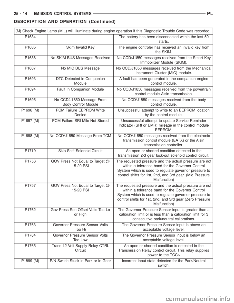
(M) Check Engine Lamp (MIL) will illuminate during engine operation if this Diagnostic Trouble Code was recorded.
P1684 The battery has been disconnected within the last 50
starts.
P1685 Skim Invalid Key The engine controler has received an invalid key from
the SKIM.
P1686 No SKIM BUS Messages Received No CCD/J1850 messages received from the Smart Key
Immobilizer Module (SKIM).
P1687 No MIC BUS Message No CCD/J1850 messages received from the Mechanical
Instrument Cluster (MIC) module.
P1693 DTC Detected in Companion
ModuleA fault has been generated in the companion engine
control module.
P1694 Fault In Companion Module No CCD/J1850 messages received from the powertrain
control module-Aisin transmission.
P1695 No CCD/J1850 Message From
Body Control ModuleNo CCD/J1850 messages received from the body
control module.
P1696 (M) PCM Failure EEPROM Write
DeniedUnsuccessful attempt to write to an EEPROM location
by the control module.
P1697 (M) PCM Failure SRI Mile Not Stored Unsuccessful attempt to update Service Reminder
Indicator (SRI or EMR) mileage in the control module
EEPROM.
P1698 (M) No CCD/J1850 Message From TCM No CCD/J1850 messages received from the electronic
transmission control module (EATX) or the Aisin
transmission controller.
P1719 Skip Shift Solenoid Circuit An open or shorted condition detected in the
transmission 2-3 gear lock-out solenoid control circuit.
P1756 GOV Press Not Equal to Target @
15-20 PSIThe requested pressure and the actual pressure are not
within a tolerance band for the Governor Control
System which is used to regulate governor pressure to
control shifts for 1st, 2nd, and 3rd gear. (Mid Pressure
Malfunction)
P1757 GOV Press Not Equal to Target @
15-20 PSIThe requested pressure and the actual pressure are not
within a tolerance band for the Governor Control
System which is used to regulate governor pressure to
control shifts for 1st, 2nd, and 3rd gear (Zero Pressure
Malfunction)
P1762 Gov Press Sen Offset Volts Too Lo
or HighThe Governor Pressure Sensor input is greater than a
calibration limit or is less than a calibration limit for 3
consecutive park/neutral calibrations.
P1763 Governor Pressure Sensor Volts
To o H iThe Governor Pressure Sensor input is above an
acceptable voltage level.
P1764 Governor Pressure Sensor Volts
Too LowThe Governor Pressure Sensor input is below an
acceptable voltage level.
P1765 Trans 12 Volt Supply Relay CTRL
CircuitAn open or shorted condition is detected in the
Transmission Relay control circuit. This relay supplies
power to the TCC>
P1899 (M) P/N Switch Stuck in Park or in Gear Incorrect input state detected for the Park/Neutral
switch.
25 - 14 EMISSION CONTROL SYSTEMSPL
DESCRIPTION AND OPERATION (Continued)
Page 1108 of 1285
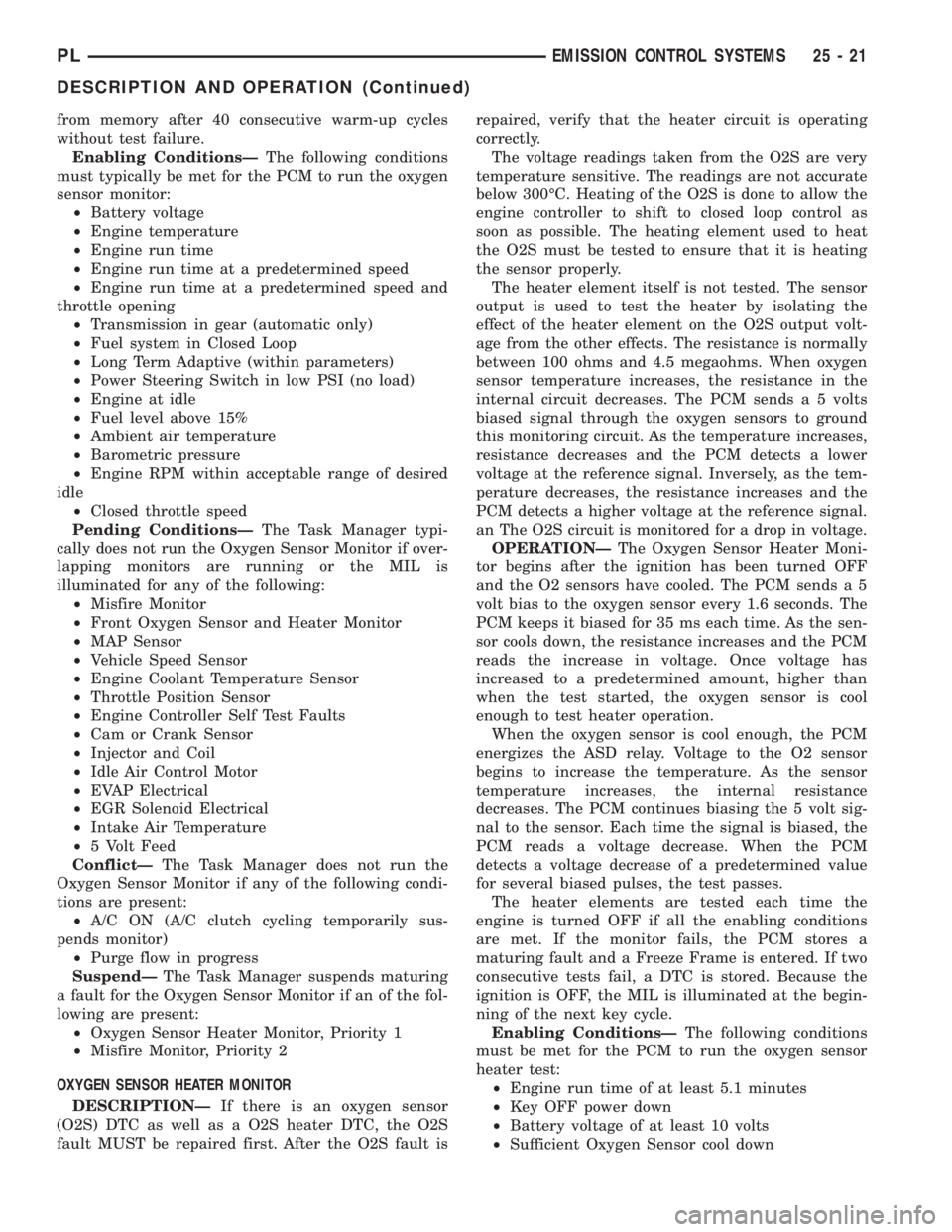
from memory after 40 consecutive warm-up cycles
without test failure.
Enabling ConditionsÐThe following conditions
must typically be met for the PCM to run the oxygen
sensor monitor:
²Battery voltage
²Engine temperature
²Engine run time
²Engine run time at a predetermined speed
²Engine run time at a predetermined speed and
throttle opening
²Transmission in gear (automatic only)
²Fuel system in Closed Loop
²Long Term Adaptive (within parameters)
²Power Steering Switch in low PSI (no load)
²Engine at idle
²Fuel level above 15%
²Ambient air temperature
²Barometric pressure
²Engine RPM within acceptable range of desired
idle
²Closed throttle speed
Pending ConditionsÐThe Task Manager typi-
cally does not run the Oxygen Sensor Monitor if over-
lapping monitors are running or the MIL is
illuminated for any of the following:
²Misfire Monitor
²Front Oxygen Sensor and Heater Monitor
²MAP Sensor
²Vehicle Speed Sensor
²Engine Coolant Temperature Sensor
²Throttle Position Sensor
²Engine Controller Self Test Faults
²Cam or Crank Sensor
²Injector and Coil
²Idle Air Control Motor
²EVAP Electrical
²EGR Solenoid Electrical
²Intake Air Temperature
²5 Volt Feed
ConflictÐThe Task Manager does not run the
Oxygen Sensor Monitor if any of the following condi-
tions are present:
²A/C ON (A/C clutch cycling temporarily sus-
pends monitor)
²Purge flow in progress
SuspendÐThe Task Manager suspends maturing
a fault for the Oxygen Sensor Monitor if an of the fol-
lowing are present:
²Oxygen Sensor Heater Monitor, Priority 1
²Misfire Monitor, Priority 2
OXYGEN SENSOR HEATER MONITOR
DESCRIPTIONÐIf there is an oxygen sensor
(O2S) DTC as well as a O2S heater DTC, the O2S
fault MUST be repaired first. After the O2S fault isrepaired, verify that the heater circuit is operating
correctly.
The voltage readings taken from the O2S are very
temperature sensitive. The readings are not accurate
below 300ÉC. Heating of the O2S is done to allow the
engine controller to shift to closed loop control as
soon as possible. The heating element used to heat
the O2S must be tested to ensure that it is heating
the sensor properly.
The heater element itself is not tested. The sensor
output is used to test the heater by isolating the
effect of the heater element on the O2S output volt-
age from the other effects. The resistance is normally
between 100 ohms and 4.5 megaohms. When oxygen
sensor temperature increases, the resistance in the
internal circuit decreases. The PCM sends a 5 volts
biased signal through the oxygen sensors to ground
this monitoring circuit. As the temperature increases,
resistance decreases and the PCM detects a lower
voltage at the reference signal. Inversely, as the tem-
perature decreases, the resistance increases and the
PCM detects a higher voltage at the reference signal.
an The O2S circuit is monitored for a drop in voltage.
OPERATIONÐThe Oxygen Sensor Heater Moni-
tor begins after the ignition has been turned OFF
and the O2 sensors have cooled. The PCM sends a 5
volt bias to the oxygen sensor every 1.6 seconds. The
PCM keeps it biased for 35 ms each time. As the sen-
sor cools down, the resistance increases and the PCM
reads the increase in voltage. Once voltage has
increased to a predetermined amount, higher than
when the test started, the oxygen sensor is cool
enough to test heater operation.
When the oxygen sensor is cool enough, the PCM
energizes the ASD relay. Voltage to the O2 sensor
begins to increase the temperature. As the sensor
temperature increases, the internal resistance
decreases. The PCM continues biasing the 5 volt sig-
nal to the sensor. Each time the signal is biased, the
PCM reads a voltage decrease. When the PCM
detects a voltage decrease of a predetermined value
for several biased pulses, the test passes.
The heater elements are tested each time the
engine is turned OFF if all the enabling conditions
are met. If the monitor fails, the PCM stores a
maturing fault and a Freeze Frame is entered. If two
consecutive tests fail, a DTC is stored. Because the
ignition is OFF, the MIL is illuminated at the begin-
ning of the next key cycle.
Enabling ConditionsÐThe following conditions
must be met for the PCM to run the oxygen sensor
heater test:
²Engine run time of at least 5.1 minutes
²Key OFF power down
²Battery voltage of at least 10 volts
²Sufficient Oxygen Sensor cool down
PLEMISSION CONTROL SYSTEMS 25 - 21
DESCRIPTION AND OPERATION (Continued)
Page 1132 of 1285
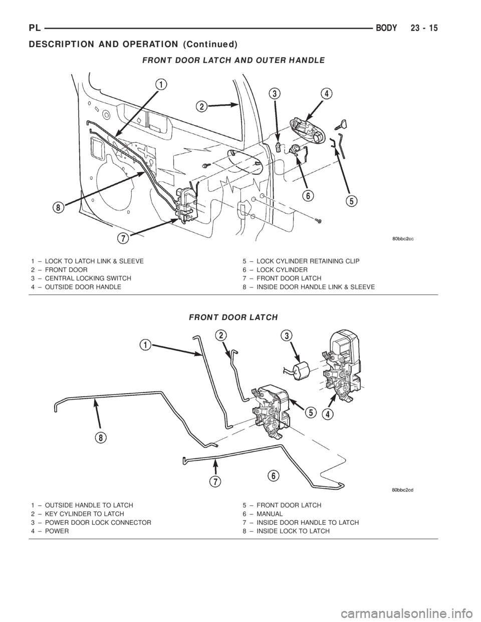
FRONT DOOR LATCH AND OUTER HANDLE
1 ± LOCK TO LATCH LINK & SLEEVE
2 ± FRONT DOOR
3 ± CENTRAL LOCKING SWITCH
4 ± OUTSIDE DOOR HANDLE5 ± LOCK CYLINDER RETAINING CLIP
6 ± LOCK CYLINDER
7 ± FRONT DOOR LATCH
8 ± INSIDE DOOR HANDLE LINK & SLEEVE
FRONT DOOR LATCH
1 ± OUTSIDE HANDLE TO LATCH
2 ± KEY CYLINDER TO LATCH
3 ± POWER DOOR LOCK CONNECTOR
4 ± POWER5 ± FRONT DOOR LATCH
6 ± MANUAL
7 ± INSIDE DOOR HANDLE TO LATCH
8 ± INSIDE LOCK TO LATCH
PLBODY 23 - 15
DESCRIPTION AND OPERATION (Continued)
Page 1160 of 1285
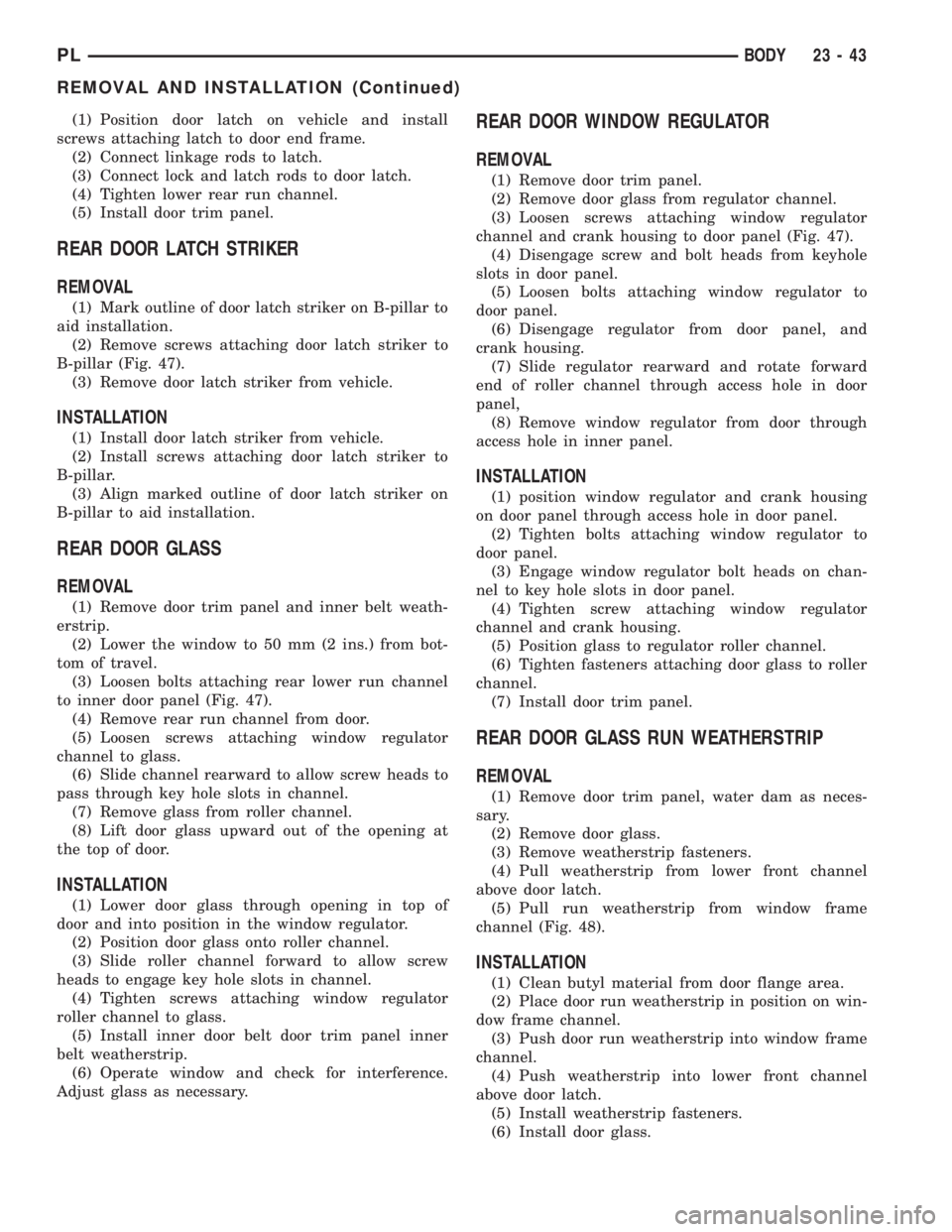
(1) Position door latch on vehicle and install
screws attaching latch to door end frame.
(2) Connect linkage rods to latch.
(3) Connect lock and latch rods to door latch.
(4) Tighten lower rear run channel.
(5) Install door trim panel.
REAR DOOR LATCH STRIKER
REMOVAL
(1) Mark outline of door latch striker on B-pillar to
aid installation.
(2) Remove screws attaching door latch striker to
B-pillar (Fig. 47).
(3) Remove door latch striker from vehicle.
INSTALLATION
(1) Install door latch striker from vehicle.
(2) Install screws attaching door latch striker to
B-pillar.
(3) Align marked outline of door latch striker on
B-pillar to aid installation.
REAR DOOR GLASS
REMOVAL
(1) Remove door trim panel and inner belt weath-
erstrip.
(2) Lower the window to 50 mm (2 ins.) from bot-
tom of travel.
(3) Loosen bolts attaching rear lower run channel
to inner door panel (Fig. 47).
(4) Remove rear run channel from door.
(5) Loosen screws attaching window regulator
channel to glass.
(6) Slide channel rearward to allow screw heads to
pass through key hole slots in channel.
(7) Remove glass from roller channel.
(8) Lift door glass upward out of the opening at
the top of door.
INSTALLATION
(1) Lower door glass through opening in top of
door and into position in the window regulator.
(2) Position door glass onto roller channel.
(3) Slide roller channel forward to allow screw
heads to engage key hole slots in channel.
(4) Tighten screws attaching window regulator
roller channel to glass.
(5) Install inner door belt door trim panel inner
belt weatherstrip.
(6) Operate window and check for interference.
Adjust glass as necessary.
REAR DOOR WINDOW REGULATOR
REMOVAL
(1) Remove door trim panel.
(2) Remove door glass from regulator channel.
(3) Loosen screws attaching window regulator
channel and crank housing to door panel (Fig. 47).
(4) Disengage screw and bolt heads from keyhole
slots in door panel.
(5) Loosen bolts attaching window regulator to
door panel.
(6) Disengage regulator from door panel, and
crank housing.
(7) Slide regulator rearward and rotate forward
end of roller channel through access hole in door
panel,
(8) Remove window regulator from door through
access hole in inner panel.
INSTALLATION
(1) position window regulator and crank housing
on door panel through access hole in door panel.
(2) Tighten bolts attaching window regulator to
door panel.
(3) Engage window regulator bolt heads on chan-
nel to key hole slots in door panel.
(4) Tighten screw attaching window regulator
channel and crank housing.
(5) Position glass to regulator roller channel.
(6) Tighten fasteners attaching door glass to roller
channel.
(7) Install door trim panel.
REAR DOOR GLASS RUN WEATHERSTRIP
REMOVAL
(1) Remove door trim panel, water dam as neces-
sary.
(2) Remove door glass.
(3) Remove weatherstrip fasteners.
(4) Pull weatherstrip from lower front channel
above door latch.
(5) Pull run weatherstrip from window frame
channel (Fig. 48).
INSTALLATION
(1) Clean butyl material from door flange area.
(2) Place door run weatherstrip in position on win-
dow frame channel.
(3) Push door run weatherstrip into window frame
channel.
(4) Push weatherstrip into lower front channel
above door latch.
(5) Install weatherstrip fasteners.
(6) Install door glass.
PLBODY 23 - 43
REMOVAL AND INSTALLATION (Continued)