2000 DODGE NEON key
[x] Cancel search: keyPage 900 of 1285
STEERING COLUMN
TABLE OF CONTENTS
page page
DESCRIPTION AND OPERATION
STEERING COLUMN......................29
STEERING COLUMN LOWER COUPLING......29
DIAGNOSIS AND TESTING
STEERING COLUMN......................30
STEERING COLUMN LOWER COUPLING......30
REMOVAL AND INSTALLATION
SERVICE WARNINGS AND CAUTIONS........31STEERING COLUMN......................31
STEERING COLUMN LOWER COUPLING......38
SPECIFICATIONS
STEERING COLUMN FASTENER TORQUE
SPECIFICATIONS.......................41
DESCRIPTION AND OPERATION
STEERING COLUMN
This vehicle is equipped with both tilt and non-tilt
steering columns. Both steering columns have been
designed to be serviced only as complete assemblies
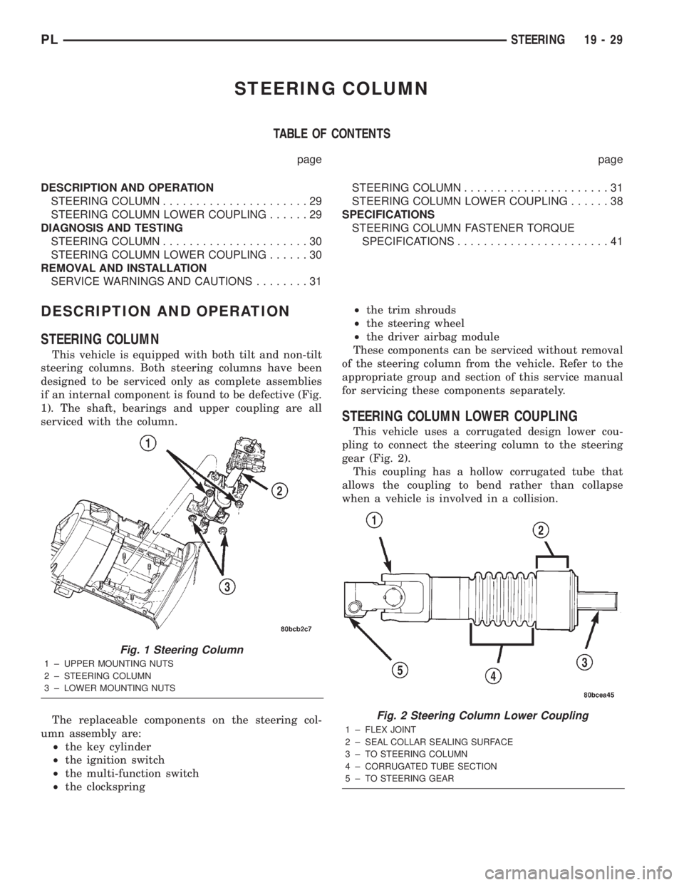
if an internal component is found to be defective (Fig.
1). The shaft, bearings and upper coupling are all
serviced with the column.
The replaceable components on the steering col-
umn assembly are:
²the key cylinder
²the ignition switch
²the multi-function switch
²the clockspring²the trim shrouds
²the steering wheel
²the driver airbag module
These components can be serviced without removal
of the steering column from the vehicle. Refer to the
appropriate group and section of this service manual
for servicing these components separately.
STEERING COLUMN LOWER COUPLING
This vehicle uses a corrugated design lower cou-
pling to connect the steering column to the steering
gear (Fig. 2).
This coupling has a hollow corrugated tube that
allows the coupling to bend rather than collapse
when a vehicle is involved in a collision.
Fig. 1 Steering Column
1 ± UPPER MOUNTING NUTS
2 ± STEERING COLUMN
3 ± LOWER MOUNTING NUTS
Fig. 2 Steering Column Lower Coupling
1 ± FLEX JOINT
2 ± SEAL COLLAR SEALING SURFACE
3 ± TO STEERING COLUMN
4 ± CORRUGATED TUBE SECTION
5 ± TO STEERING GEAR
PLSTEERING 19 - 29
Page 904 of 1285
CAUTION: When installing a wheel puller on the
steering wheel, be sure the puller bolts are fully
seated in the threaded holes on the steering wheel.
If the bolts are not fully seated in the threaded
holes, the threads may be stripped out of the steer-
ing wheel when attempting to remove the steering
wheel. Also, thread the retaining nut back on the
end of the shaft until it is flush with the shaft end to
avoid damage to the shaft threads by the wheel
puller.
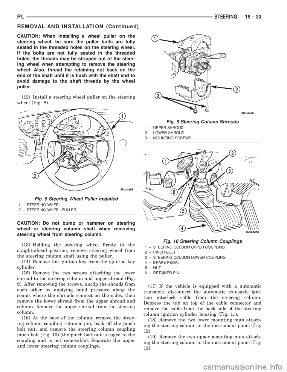
(12) Install a steering wheel puller on the steering
wheel (Fig. 8).
CAUTION: Do not bump or hammer on steering
wheel or steering column shaft when removing
steering wheel from steering column.
(13) Holding the steering wheel firmly in the
staight-ahead position, remove steering wheel from
the steering column shaft using the puller.
(14) Remove the ignition key from the ignition key
cylinder.
(15) Remove the two screws attaching the lower
shroud to the steering column and upper shroud (Fig.
9). After removing the screws, unclip the shouds from
each other by applying hand pressure along the
seams where the shrouds connect on the sides, then
remove the lower shroud from the upper shroud and
column. Remove the upper shroud from the steering
column.
(16) At the base of the column, remove the steer-
ing column coupling retainer pin, back off the pinch
bolt nut, and remove the steering column coupling
pinch bolt (Fig. 10) (the pinch bolt nut is caged to the
coupling and is not removable). Separate the upper
and lower steering column couplings.(17) If the vehicle is equipped with a automatic
transaxle, disconnect the automatic transaxle igni-
tion interlock cable from the steering column.
Depress the tab on top of the cable connector and
remove the cable from the back side of the steering
column ignition cylinder housing (Fig. 11).
(18) Remove the two lower mounting nuts attach-
ing the steering column to the instrument panel (Fig.
12).
(19) Remove the two upper mounting nuts attach-
ing the steering column to the instrument panel (Fig.
12).
Fig. 8 Steering Wheel Puller Installed
1 ± STEERING WHEEL
2 ± STEERING WHEEL PULLER
Fig. 9 Steering Column Shrouds
1 ± UPPER SHROUD
2 ± LOWER SHROUD
3 ± MOUNTING SCREWS
Fig. 10 Steering Column Couplings
1 ± STEERING COLUMN UPPER COUPLING
2 ± PINCH BOLT
3 ± STEERING COLUMN LOWER COUPLING
4 ± BRAKE PEDAL
5 ± NUT
6 ± RETAINER PIN
PLSTEERING 19 - 33
REMOVAL AND INSTALLATION (Continued)
Page 905 of 1285
(20) Lower the steering column away from the
instrument panel.
(21) Disconnect the wiring harness electrical con-
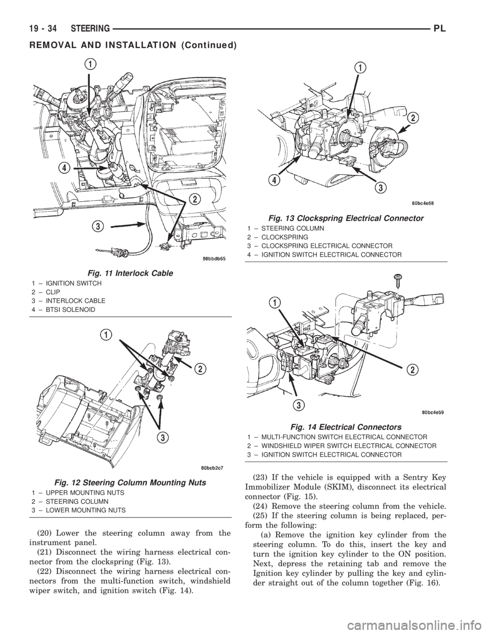
nector from the clockspring (Fig. 13).
(22) Disconnect the wiring harness electrical con-
nectors from the multi-function switch, windshield
wiper switch, and ignition switch (Fig. 14).(23) If the vehicle is equipped with a Sentry Key
Immobilizer Module (SKIM), disconnect its electrical
connector (Fig. 15).
(24) Remove the steering column from the vehicle.
(25) If the steering column is being replaced, per-
form the following:
(a) Remove the ignition key cylinder from the
steering column. To do this, insert the key and
turn the ignition key cylinder to the ON position.
Next, depress the retaining tab and remove the
Ignition key cylinder by pulling the key and cylin-
der straight out of the column together (Fig. 16).
Fig. 11 Interlock Cable
1 ± IGNITION SWITCH
2 ± CLIP
3 ± INTERLOCK CABLE
4 ± BTSI SOLENOID
Fig. 12 Steering Column Mounting Nuts
1 ± UPPER MOUNTING NUTS
2 ± STEERING COLUMN
3 ± LOWER MOUNTING NUTS
Fig. 13 Clockspring Electrical Connector
1 ± STEERING COLUMN
2 ± CLOCKSPRING
3 ± CLOCKSPRING ELECTRICAL CONNECTOR
4 ± IGNITION SWITCH ELECTRICAL CONNECTOR
Fig. 14 Electrical Connectors
1 ± MULTI-FUNCTION SWITCH ELECTRICAL CONNECTOR
2 ± WINDSHIELD WIPER SWITCH ELECTRICAL CONNECTOR
3 ± IGNITION SWITCH ELECTRICAL CONNECTOR
19 - 34 STEERINGPL
REMOVAL AND INSTALLATION (Continued)
Page 906 of 1285
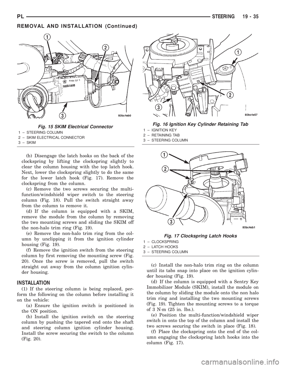
(b) Disengage the latch hooks on the back of the
clockspring by lifting the clockspring slightly to
clear the column housing with the top latch hook.
Next, lower the clockspring slightly to do the same
for the lower latch hook (Fig. 17). Remove the
clockspring from the column.
(c) Remove the two screws securing the multi-
function/windshield wiper switch to the steering
column (Fig. 18). Pull the switch straight away
from the column to remove it.
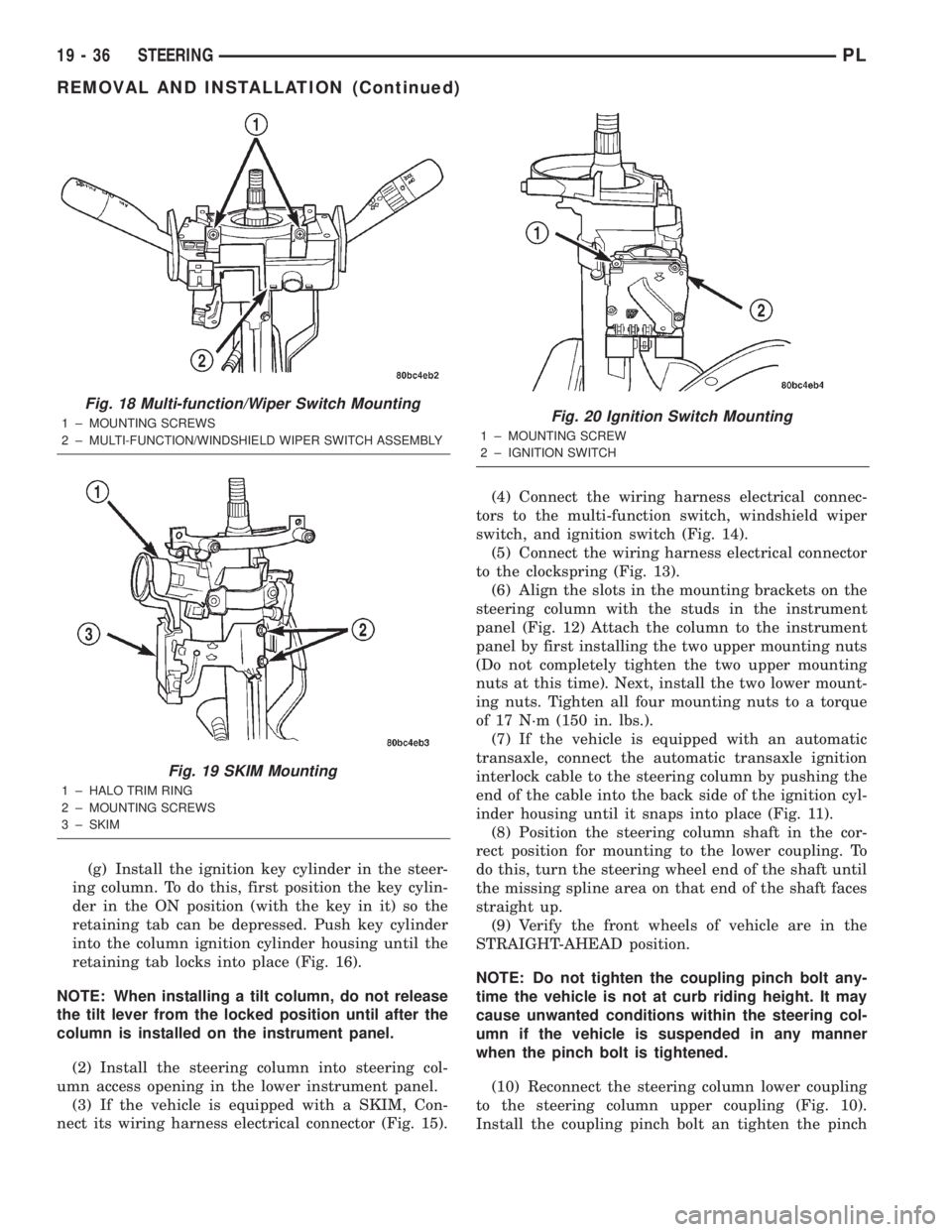
(d) If the column is equipped with a SKIM,
remove the module from the column by removing
the two mounting screws and sliding the SKIM off
the non-halo trim ring (Fig. 19).
(e) Remove the non-halo trim ring from the col-
umn by unclipping it from the ignition cylinder
housing (Fig. 19).
(f) Remove the ignition switch from the steering
column by first removing the mounting screw (Fig.
20). Once the screw is removed, pull the switch
straight out away from the column ignition cylin-
der housing.
INSTALLATION
(1) If the steering column is being replaced, per-
form the following on the column before installing it
on the vehicle:
(a) Ensure the ignition switch is positioned in
the ON position.
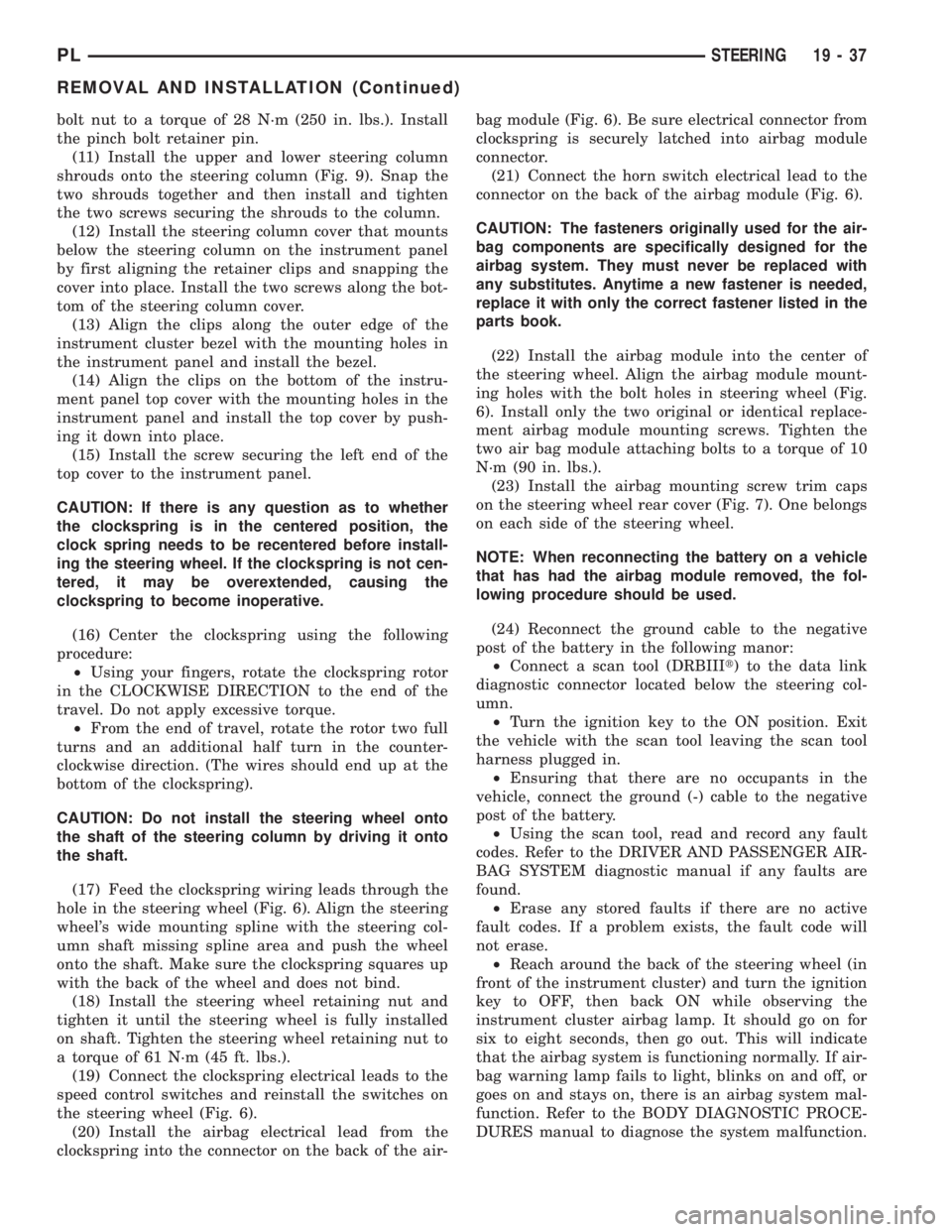
(b) Install the ignition switch on the steering
column by pushing the tapered end onto the shaft
and steering column ignition cylinder housing.
Install the screw securing the switch to the column
(Fig. 20).(c) Install the non-halo trim ring on the column
until its tabs snap into place on the ignition cylin-
der housing (Fig. 19).
(d) If the column is equipped with a Sentry Key
Immobilizer Module (SKIM), install the module on
the column by sliding the module onto the non halo
trim ring and installing the two mounting screws
(Fig. 19). Tighten the mounting screws to a torque
of 3 N´m (25 in. lbs.).
(e) Position the multi-function/windshield wiper
switch in onto the top of the column and install the
two screws securing the switch in place (Fig. 18).
(f) Place the clockspring onto the end of the col-
umn engaging the clockspring latch hooks into the
column (Fig. 17).
Fig. 15 SKIM Electrical Connector
1 ± STEERING COLUMN
2 ± SKIM ELECTRICAL CONNECTOR
3 ± SKIM
Fig. 16 Ignition Key Cylinder Retaining Tab
1 ± IGNITION KEY
2 ± RETAINING TAB
3 ± STEERING COLUMN
Fig. 17 Clockspring Latch Hooks
1 ± CLOCKSPRING
2 ± LATCH HOOKS
3 ± STEERING COLUMN
PLSTEERING 19 - 35
REMOVAL AND INSTALLATION (Continued)
Page 907 of 1285
(g) Install the ignition key cylinder in the steer-
ing column. To do this, first position the key cylin-
der in the ON position (with the key in it) so the
retaining tab can be depressed. Push key cylinder
into the column ignition cylinder housing until the
retaining tab locks into place (Fig. 16).
NOTE: When installing a tilt column, do not release
the tilt lever from the locked position until after the
column is installed on the instrument panel.
(2) Install the steering column into steering col-
umn access opening in the lower instrument panel.
(3) If the vehicle is equipped with a SKIM, Con-
nect its wiring harness electrical connector (Fig. 15).(4) Connect the wiring harness electrical connec-
tors to the multi-function switch, windshield wiper
switch, and ignition switch (Fig. 14).
(5) Connect the wiring harness electrical connector
to the clockspring (Fig. 13).
(6) Align the slots in the mounting brackets on the
steering column with the studs in the instrument
panel (Fig. 12) Attach the column to the instrument
panel by first installing the two upper mounting nuts
(Do not completely tighten the two upper mounting
nuts at this time). Next, install the two lower mount-
ing nuts. Tighten all four mounting nuts to a torque
of 17 N´m (150 in. lbs.).
(7) If the vehicle is equipped with an automatic
transaxle, connect the automatic transaxle ignition
interlock cable to the steering column by pushing the
end of the cable into the back side of the ignition cyl-
inder housing until it snaps into place (Fig. 11).
(8) Position the steering column shaft in the cor-
rect position for mounting to the lower coupling. To
do this, turn the steering wheel end of the shaft until
the missing spline area on that end of the shaft faces
straight up.
(9) Verify the front wheels of vehicle are in the
STRAIGHT-AHEAD position.
NOTE: Do not tighten the coupling pinch bolt any-
time the vehicle is not at curb riding height. It may
cause unwanted conditions within the steering col-
umn if the vehicle is suspended in any manner
when the pinch bolt is tightened.
(10) Reconnect the steering column lower coupling
to the steering column upper coupling (Fig. 10).
Install the coupling pinch bolt an tighten the pinch
Fig. 18 Multi-function/Wiper Switch Mounting
1 ± MOUNTING SCREWS
2 ± MULTI-FUNCTION/WINDSHIELD WIPER SWITCH ASSEMBLY
Fig. 19 SKIM Mounting
1 ± HALO TRIM RING
2 ± MOUNTING SCREWS
3 ± SKIM
Fig. 20 Ignition Switch Mounting
1 ± MOUNTING SCREW
2 ± IGNITION SWITCH
19 - 36 STEERINGPL
REMOVAL AND INSTALLATION (Continued)
Page 908 of 1285
bolt nut to a torque of 28 N´m (250 in. lbs.). Install
the pinch bolt retainer pin.
(11) Install the upper and lower steering column
shrouds onto the steering column (Fig. 9). Snap the
two shrouds together and then install and tighten
the two screws securing the shrouds to the column.
(12) Install the steering column cover that mounts
below the steering column on the instrument panel
by first aligning the retainer clips and snapping the
cover into place. Install the two screws along the bot-
tom of the steering column cover.
(13) Align the clips along the outer edge of the
instrument cluster bezel with the mounting holes in
the instrument panel and install the bezel.
(14) Align the clips on the bottom of the instru-
ment panel top cover with the mounting holes in the
instrument panel and install the top cover by push-
ing it down into place.
(15) Install the screw securing the left end of the
top cover to the instrument panel.
CAUTION: If there is any question as to whether
the clockspring is in the centered position, the
clock spring needs to be recentered before install-
ing the steering wheel. If the clockspring is not cen-
tered, it may be overextended, causing the
clockspring to become inoperative.
(16) Center the clockspring using the following
procedure:
²Using your fingers, rotate the clockspring rotor
in the CLOCKWISE DIRECTION to the end of the
travel. Do not apply excessive torque.
²From the end of travel, rotate the rotor two full
turns and an additional half turn in the counter-
clockwise direction. (The wires should end up at the
bottom of the clockspring).
CAUTION: Do not install the steering wheel onto
the shaft of the steering column by driving it onto
the shaft.
(17) Feed the clockspring wiring leads through the
hole in the steering wheel (Fig. 6). Align the steering
wheel's wide mounting spline with the steering col-
umn shaft missing spline area and push the wheel
onto the shaft. Make sure the clockspring squares up
with the back of the wheel and does not bind.
(18) Install the steering wheel retaining nut and
tighten it until the steering wheel is fully installed
on shaft. Tighten the steering wheel retaining nut to
a torque of 61 N´m (45 ft. lbs.).
(19) Connect the clockspring electrical leads to the
speed control switches and reinstall the switches on
the steering wheel (Fig. 6).
(20) Install the airbag electrical lead from the
clockspring into the connector on the back of the air-bag module (Fig. 6). Be sure electrical connector from
clockspring is securely latched into airbag module
connector.
(21) Connect the horn switch electrical lead to the
connector on the back of the airbag module (Fig. 6).
CAUTION: The fasteners originally used for the air-
bag components are specifically designed for the
airbag system. They must never be replaced with
any substitutes. Anytime a new fastener is needed,
replace it with only the correct fastener listed in the
parts book.
(22) Install the airbag module into the center of
the steering wheel. Align the airbag module mount-
ing holes with the bolt holes in steering wheel (Fig.
6). Install only the two original or identical replace-
ment airbag module mounting screws. Tighten the
two air bag module attaching bolts to a torque of 10
N´m (90 in. lbs.).
(23) Install the airbag mounting screw trim caps
on the steering wheel rear cover (Fig. 7). One belongs
on each side of the steering wheel.
NOTE: When reconnecting the battery on a vehicle
that has had the airbag module removed, the fol-
lowing procedure should be used.
(24) Reconnect the ground cable to the negative
post of the battery in the following manor:
²Connect a scan tool (DRBIIIt) to the data link
diagnostic connector located below the steering col-
umn.
²Turn the ignition key to the ON position. Exit
the vehicle with the scan tool leaving the scan tool
harness plugged in.
²Ensuring that there are no occupants in the
vehicle, connect the ground (-) cable to the negative
post of the battery.
²Using the scan tool, read and record any fault
codes. Refer to the DRIVER AND PASSENGER AIR-
BAG SYSTEM diagnostic manual if any faults are
found.
²Erase any stored faults if there are no active
fault codes. If a problem exists, the fault code will
not erase.
²Reach around the back of the steering wheel (in
front of the instrument cluster) and turn the ignition
key to OFF, then back ON while observing the
instrument cluster airbag lamp. It should go on for
six to eight seconds, then go out. This will indicate
that the airbag system is functioning normally. If air-
bag warning lamp fails to light, blinks on and off, or
goes on and stays on, there is an airbag system mal-
function. Refer to the BODY DIAGNOSTIC PROCE-
DURES manual to diagnose the system malfunction.
PLSTEERING 19 - 37
REMOVAL AND INSTALLATION (Continued)
Page 909 of 1285
(25) Turn the key to OFF and remove the scan tool
from the vehicle.
(26) Test the operation of the horn, wipers and any
other functions that are steering column operated. If
applicable, reset the radio and the clock.
(27) If the steering column is a tilt column, verify
the tilt mechanism operates properly.
(28) Road test the vehicle to ensure proper opera-
tion of the steering system and the speed control sys-
tem.
STEERING COLUMN LOWER COUPLING
NOTE: Before proceeding with this removal and
installation procedure, review SERVICE WARNINGS
AND CAUTIONS at the beginning of REMOVAL AND
INSTALLATION in this section and in STEERING
GEAR.
REMOVAL
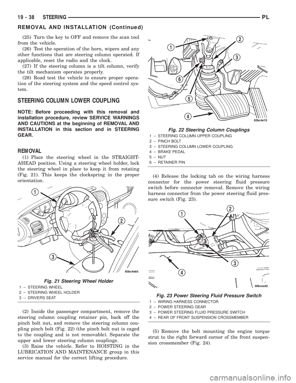
(1) Place the steering wheel in the STRAIGHT-
AHEAD position. Using a steering wheel holder, lock
the steering wheel in place to keep it from rotating
(Fig. 21). This keeps the clockspring in the proper
orientation.
(2) Inside the passenger compartment, remove the
steering column coupling retainer pin, back off the
pinch bolt nut, and remove the steering column cou-
pling pinch bolt (Fig. 22) (the pinch bolt nut is caged
to the coupling and is not removable). Separate the
upper and lower steering column couplings.
(3) Raise the vehicle. Refer to HOISTING in the
LUBRICATION AND MAINTENANCE group in this
service manual for the correct lifting procedure.(4) Release the locking tab on the wiring harness
connector for the power steering fluid pressure
switch before connector removal. Remove the wiring
harness connector from the power steering fluid pres-
sure switch (Fig. 23).
(5) Remove the bolt mounting the engine torque
strut to the right forward corner of the front suspen-
sion crossmember (Fig. 24).
Fig. 21 Steering Wheel Holder
1 ± STEERING WHEEL
2 ± STEERING WHEEL HOLDER
3 ± DRIVERS SEAT
Fig. 22 Steering Column Couplings
1 ± STEERING COLUMN UPPER COUPLING
2 ± PINCH BOLT
3 ± STEERING COLUMN LOWER COUPLING
4 ± BRAKE PEDAL
5 ± NUT
6 ± RETAINER PIN
Fig. 23 Power Steering Fluid Pressure Switch
1 ± WIRING HARNESS CONNECTOR
2 ± POWER STEERING GEAR
3 ± POWER STEERING FLUID PRESSURE SWITCH
4 ± REAR OF FRONT SUSPENSION CROSSMEMBER
19 - 38 STEERINGPL
REMOVAL AND INSTALLATION (Continued)
Page 954 of 1285
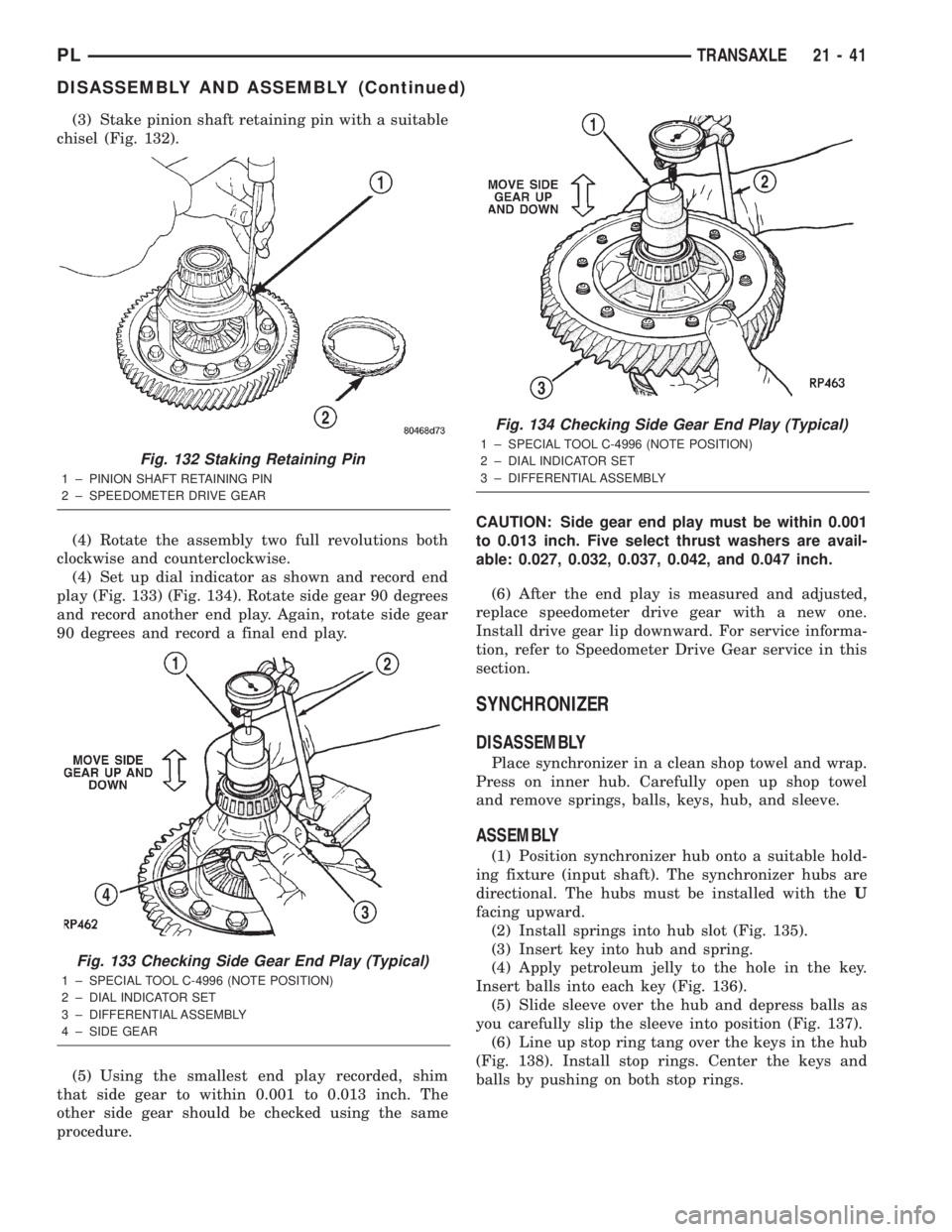
(3) Stake pinion shaft retaining pin with a suitable
chisel (Fig. 132).
(4) Rotate the assembly two full revolutions both
clockwise and counterclockwise.
(4) Set up dial indicator as shown and record end
play (Fig. 133) (Fig. 134). Rotate side gear 90 degrees
and record another end play. Again, rotate side gear
90 degrees and record a final end play.
(5) Using the smallest end play recorded, shim
that side gear to within 0.001 to 0.013 inch. The
other side gear should be checked using the same
procedure.CAUTION: Side gear end play must be within 0.001
to 0.013 inch. Five select thrust washers are avail-
able: 0.027, 0.032, 0.037, 0.042, and 0.047 inch.
(6) After the end play is measured and adjusted,
replace speedometer drive gear with a new one.
Install drive gear lip downward. For service informa-
tion, refer to Speedometer Drive Gear service in this
section.
SYNCHRONIZER
DISASSEMBLY
Place synchronizer in a clean shop towel and wrap.
Press on inner hub. Carefully open up shop towel
and remove springs, balls, keys, hub, and sleeve.
ASSEMBLY
(1) Position synchronizer hub onto a suitable hold-
ing fixture (input shaft). The synchronizer hubs are
directional. The hubs must be installed with theU
facing upward.
(2) Install springs into hub slot (Fig. 135).
(3) Insert key into hub and spring.
(4) Apply petroleum jelly to the hole in the key.
Insert balls into each key (Fig. 136).
(5) Slide sleeve over the hub and depress balls as
you carefully slip the sleeve into position (Fig. 137).
(6) Line up stop ring tang over the keys in the hub
(Fig. 138). Install stop rings. Center the keys and
balls by pushing on both stop rings.
Fig. 132 Staking Retaining Pin
1 ± PINION SHAFT RETAINING PIN
2 ± SPEEDOMETER DRIVE GEAR
Fig. 133 Checking Side Gear End Play (Typical)
1 ± SPECIAL TOOL C-4996 (NOTE POSITION)
2 ± DIAL INDICATOR SET
3 ± DIFFERENTIAL ASSEMBLY
4 ± SIDE GEAR
Fig. 134 Checking Side Gear End Play (Typical)
1 ± SPECIAL TOOL C-4996 (NOTE POSITION)
2 ± DIAL INDICATOR SET
3 ± DIFFERENTIAL ASSEMBLY
PLTRANSAXLE 21 - 41
DISASSEMBLY AND ASSEMBLY (Continued)