2000 DODGE NEON key
[x] Cancel search: keyPage 955 of 1285
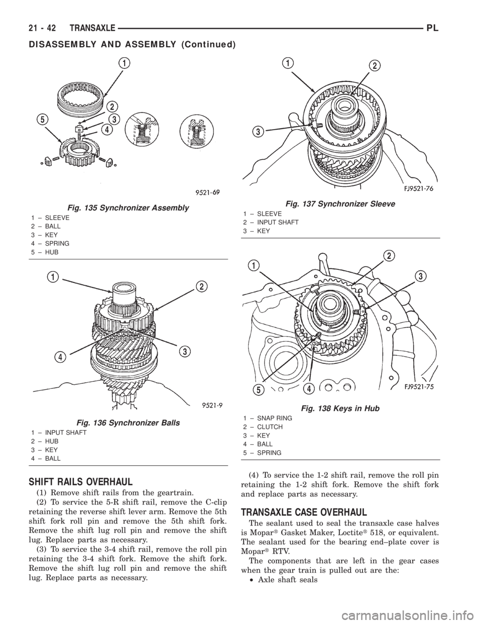
SHIFT RAILS OVERHAUL
(1) Remove shift rails from the geartrain.
(2) To service the 5-R shift rail, remove the C-clip
retaining the reverse shift lever arm. Remove the 5th
shift fork roll pin and remove the 5th shift fork.
Remove the shift lug roll pin and remove the shift
lug. Replace parts as necessary.
(3) To service the 3-4 shift rail, remove the roll pin
retaining the 3-4 shift fork. Remove the shift fork.
Remove the shift lug roll pin and remove the shift
lug. Replace parts as necessary.(4) To service the 1-2 shift rail, remove the roll pin
retaining the 1-2 shift fork. Remove the shift fork
and replace parts as necessary.
TRANSAXLE CASE OVERHAUL
The sealant used to seal the transaxle case halves
is MopartGasket Maker, Loctitet518, or equivalent.
The sealant used for the bearing end±plate cover is
MopartRTV.
The components that are left in the gear cases
when the gear train is pulled out are the:
²Axle shaft seals
Fig. 135 Synchronizer Assembly
1 ± SLEEVE
2 ± BALL
3 ± KEY
4 ± SPRING
5 ± HUB
Fig. 136 Synchronizer Balls
1 ± INPUT SHAFT
2 ± HUB
3 ± KEY
4 ± BALL
Fig. 137 Synchronizer Sleeve
1 ± SLEEVE
2 ± INPUT SHAFT
3 ± KEY
Fig. 138 Keys in Hub
1 ± SNAP RING
2 ± CLUTCH
3 ± KEY
4 ± BALL
5 ± SPRING
21 - 42 TRANSAXLEPL
DISASSEMBLY AND ASSEMBLY (Continued)
Page 961 of 1285
SHIFT CROSSOVER SHAFT BUSHING
REMOVAL
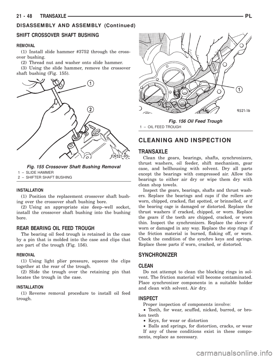
(1) Install slide hammer #3752 through the cross-
over bushing.
(2) Thread nut and washer onto slide hammer.
(3) Using the slide hammer, remove the crossover
shaft bushing (Fig. 155).
INSTALLATION
(1) Position the replacement crossover shaft bush-
ing over the crossover shaft bushing bore.
(2) Using an appropriate size deep±well socket,
install the crossover shaft bushing into the bushing
bore.
REAR BEARING OIL FEED TROUGH
The bearing oil feed trough is retained in the case
by a pin that is molded into the case and clips that
are part of the trough (Fig. 156).
REMOVAL
(1) Using light plier pressure, squeeze the clips
together at the rear of the trough.
(2) Slide the trough over the retaining pin that
locates the trough in the case.
INSTALLATION
(1) Reverse removal procedure to install oil feed
trough.
CLEANING AND INSPECTION
TRANSAXLE
Clean the gears, bearings, shafts, synchronizers,
thrust washers, oil feeder, shift mechanism, gear
case, and bellhousing with solvent. Dry all parts
except the bearings with compressed air. Allow the
bearings to either air dry or wipe them dry with
clean shop towels.
Inspect the gears, bearings, shafts and thrust wash-
ers. Replace the bearings and cups if the rollers are
worn, chipped, cracked, flat spotted, or brinnelled, or if
the bearing cage is damaged or distorted. Replace the
thrust washers if cracked, chipped, or worn. Replace
the gears if the teeth are chipped, cracked, or worn
thin. Inspect the synchronizers. Replace the sleeve if
worn or damaged in any way. Replace the stop rings if
the friction material is burned, flaking off, or worn.
Check the condition of the synchro keys and springs.
Replace these parts if worn, cracked, or distorted.
SYNCHRONIZER
CLEAN
Do not attempt to clean the blocking rings in sol-
vent. The friction material will become contaminated.
Place synchronizer components in a suitable holder
and clean with solvent. Air dry.
INSPECT
Proper inspection of components involve:
²Teeth, for wear, scuffed, nicked, burred, or bro-
ken teeth
²Keys, for wear or distortion
²Balls and springs, for distortion, cracks, or wear
If any of these conditions exist in these compo-
nents, replace as necessary.
Fig. 155 Crossover Shaft Bushing Removal
1 ± SLIDE HAMMER
2 ± SHIFTER SHAFT BUSHING
Fig. 156 Oil Feed Trough
1 ± OIL FEED TROUGH
21 - 48 TRANSAXLEPL
DISASSEMBLY AND ASSEMBLY (Continued)
Page 970 of 1285
The kickdown valve makes possible a forced down-
shift from third to second, second to first, or third to
first (depending on vehicle speed). This can be done
by depressing the accelerator pedal past the detent
feel near wide open throttle.
The shuttle valve has two separate functions and
performs each independently of the other. The first is
providing fast release of the kickdown band, and
smooth front clutch engagement when a lift-foot
upshift from second to third is made. The second
function is to regulate the application of the kick-
down servo and band when making third±to±second
kickdown.
The bypass valve provides for smooth application
of the kickdown band on 1-2 upshifts.
The torque converter clutch solenoid allows for the
electronic control of the torque converter clutch. It
also disengages the torque converter at closed throt-
tle. This is done during engine warm-up and part-
throttle acceleration.
The switch valve directs oil to apply the torque
converter clutch in one position. The switch valve
releases the torque converter clutch in the other posi-
tion.
CLUTCHES, BAND SERVOS, AND
ACCUMULATOR
The front and rear clutch pistons, and both servo
pistons, are moved hydraulically to engage the
clutches and apply the bands. The pistons are
released by spring tension when hydraulic pressure
is released. On the 2-3 upshift, the kickdown servo
piston is released by spring tension and hydraulic
pressure.
The accumulator controls the hydraulic pressure
on the apply±side of the kickdown servo during the
1-2 upshift; thereby cushioning the kickdown band
application at any throttle position.
BRAKE TRANSMISSION SHIFT INTERLOCK
SYSTEM
The Brake Transmission Shifter/Ignition Interlock
(BTSI) is a cable and solenoid operated system. It
interconnects the automatic transmission floor
mounted shifter to the steering column ignition
switch. The system locks the shifter into the PARK
position. The interlock system is engaged whenever
the ignition switch is in the LOCK or ACCESSORY
position. An additional electrically activated feature
will prevent shifting out of the PARK position unless
the brake pedal is depressed at least one-half inch. A
magnetic holding device integral to the interlock
cable is energized when the ignition is in the RUN
position. When the key is in the RUN position and
the brake pedal is depressed, the shifter is unlocked
and will move into any position. The interlock systemalso prevents the ignition switch from being turned
to the LOCK or ACCESSORY position, unless the
shifter is in the gated PARK position.
The following chart describes the normal operation
of the Brake Transmission Shift Interlock (BTSI) sys-
tem. If the ªexpected responseº differs from the vehi-
cle's response, then system repair and/or adjustment
is necessary.
GEARSHIFT AND PARKING LOCK CONTROLS
The transaxle is controlled by alever typegear-
shift incorporated within the console. The control has
six selector lever positions: P (Park), R (Reverse), N
(Neutral), and D (Drive), 2 (Second), and 1 (First).
The parking lock is applied by moving the selector
lever past a gate to the (P) position.Do not apply
the parking lock until the vehicle has stopped;
otherwise, a severe banging noise will occur.
COOLER BYPASS VALVE
Some 31TH transaxles are equipped with a cooler
bypass valve (Fig. 2). The valve is designed to bypass
the transaxle oil cooler circuit in cold weather condi-
tions, or when circuit restriction exceeds 25±30 p.s.i.
The valve consists of an integrated check ball and
spring, and a return tube to carry bypassed oil back
to the pump. The bypass valve is mounted to the
valve body transfer plate and is sealed with a rubber
o-ring seal (Fig. 3).
ACTION EXPECTED RESPONSE
1. Turn key to the ªOFFº
position.1. Shifter CAN be shifted
out of park.
2. Turn key to the
9ON/RUNº position.2. Shifter CANNOT be
shifted out of park.
3. Turn key to the
ªON/RUNº position and
depress the brake pedal.3. Shifter CAN be shifted
out of park.
4. Leave shifter in any
gear and try to return key
to the ªLOCKº or9ACCº
position.4. Key cannot be
returned to the ªLOCKº or
ªACCº position.
5. Return shifter to
ªPARKº and try to remove
the key.5. Key can be removed
(after returning to ªLOCKº
position).
6. With the key removed,
try to shift out of ªPARKº.6. Shifter cannot be
shifted out of ªPARKº.
NOTE: Any failure to meet these expected
responses requires system adjustment or repair.
PLTRANSAXLE 21 - 57
DESCRIPTION AND OPERATION (Continued)
Page 983 of 1285
LOW AND REVERSE SERVO (REAR)
Direct air pressure into LOW/REVERSE SERVO
APPLY passage. Operation of servo is indicated by a
tightening of rear band. Spring tension on servo pis-
ton should release the band.
If clutches and servos operate properly, no upshift
indicates that a malfunction exists in the valve body.
FLUID LEAKAGE-TRANSAXLE TORQUE
CONVERTER HOUSING AREA
(1) Check for source of leakage.
(2) Since fluid leakage near the torque converter
area may be from an engine oil leak, the area should
be checked closely. Factory fill fluid is dyed red and,
therefore, can be distinguished from engine oil.
(3) Prior to removing the transaxle, perform the
following checks:
(4) When leakage is determined to originate from
the transaxle, check fluid level prior to removal of
the transaxle and torque converter.
(5) High oil level can result in oil leakage out the
vent in the dipstick. If the fluid level is high, adjust
to proper level.
(6) After performing this operation, inspect for
leakage. If a leak persists, perform the following
operation on the vehicle. This will determine if the
torque converter or transaxle is leaking.
TORQUE CONVERTER LEAKAGE
Possible sources of torque converter leakage are:
²Torque converter weld leaks at the outside diam-
eter (peripheral) weld
²Torque converter hub weld
²Torque converter impeller shell cracked adjacent
to hub
²At drive lug welds
NOTE: Hub weld is inside and not visible. Do not
attempt to repair. Replace torque converter.
BRAKE TRANSMISSION SHIFT INTERLOCK
The following chart describes the normal operation
of the Brake Transmission Shift Interlock (BTSI) sys-
tem. If the ªexpected responseº differs from the vehi-
cle's response, then system repair and/or adjustment
is necessary. Refer to Brake Transmission Interlock
Removal and Installation or Adjustment in this
Group.
SERVICE PROCEDURES
TRANSAXLE FLUID AND FILTER SERVICE
NOTE: Refer to Group 0, Lubrication and Mainte-
nance, or the vehicle owner's manual, for the rec-
ommended maintenance (fluid/filter change)
intervals for this transaxle.
NOTE: Only fluids of the type labeled MoparT
ATF+4 (Automatic Transmission Fluid) Type 9602
should be used. A filter change should be made at
the time of the transmission oil change. The magnet
(on the inside of the oil pan) should also be cleaned
with a clean, dry cloth.
NOTE: If the transaxle is disassembled for any rea-
son, the fluid and filter should be changed.
FLUID/FILTER SERVICE (RECOMMENDED)
(1) Raise vehicle on a hoist (See Lubrication,
Group 0). Place a drain container with a large open-
ing, under transaxle oil pan.
(2) Loosen pan bolts and tap the pan at one corner
to break it loose allowing fluid to drain, then remove
the oil pan.
(3) Install a new filter and o-ring on bottom of the
valve body and tighten retaining screws to 5 N´m (40
in. lbs.).
ACTION EXPECTED RESPONSE
1. Turn key to the ªOFFº
position.1. Shifter CAN be shifted
out of park.
2. Turn key to the
9ON/RUNº position.2. Shifter CANNOT be
shifted out of park.
3. Turn key to the
ªON/RUNº position and
depress the brake pedal.3. Shifter CAN be shifted
out of park.
4. Leave shifter in any
gear and try to return key
to the ªLOCKº or9ACCº
position.4. Key cannot be
returned to the ªLOCKº or
ªACCº position.
5. Return shifter to
ªPARKº and try to remove
the key.5. Key can be removed
(after returning to ªLOCKº
position).
6. With the key removed,
try to shift out of ªPARKº.6. Shifter cannot be
shifted out of ªPARKº.
NOTE: Any failure to meet these expected
responses requires system adjustment or repair.
21 - 70 TRANSAXLEPL
DIAGNOSIS AND TESTING (Continued)
Page 993 of 1285
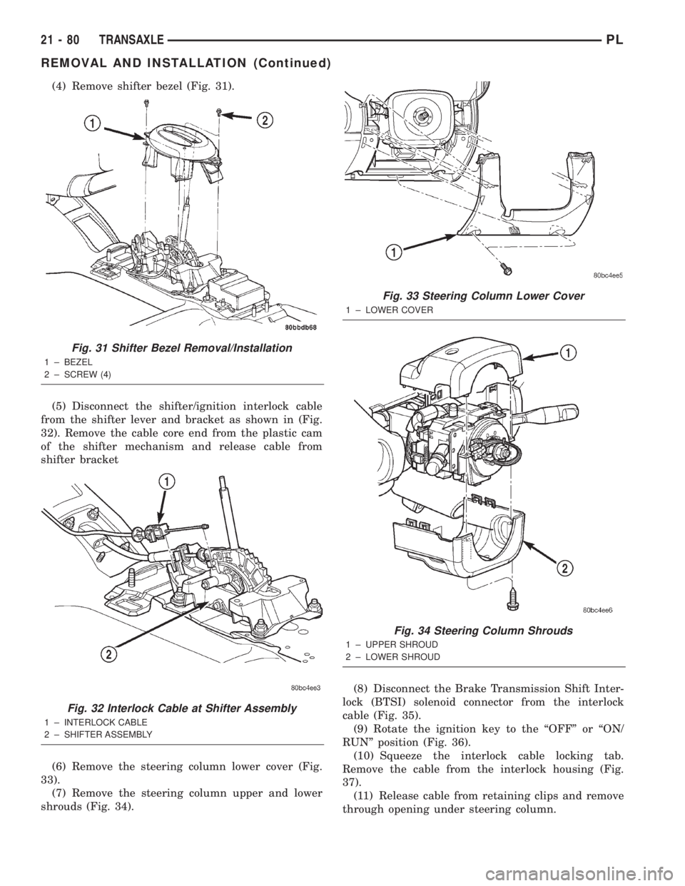
(4) Remove shifter bezel (Fig. 31).
(5) Disconnect the shifter/ignition interlock cable
from the shifter lever and bracket as shown in (Fig.
32). Remove the cable core end from the plastic cam
of the shifter mechanism and release cable from
shifter bracket
(6) Remove the steering column lower cover (Fig.
33).
(7) Remove the steering column upper and lower
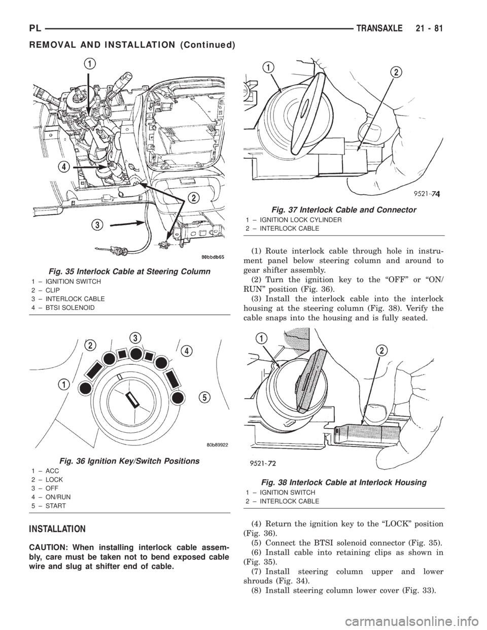
shrouds (Fig. 34).(8) Disconnect the Brake Transmission Shift Inter-
lock (BTSI) solenoid connector from the interlock
cable (Fig. 35).
(9) Rotate the ignition key to the ªOFFº or ªON/
RUNº position (Fig. 36).
(10) Squeeze the interlock cable locking tab.
Remove the cable from the interlock housing (Fig.
37).
(11) Release cable from retaining clips and remove
through opening under steering column.
Fig. 31 Shifter Bezel Removal/Installation
1 ± BEZEL
2 ± SCREW (4)
Fig. 32 Interlock Cable at Shifter Assembly
1 ± INTERLOCK CABLE
2 ± SHIFTER ASSEMBLY
Fig. 33 Steering Column Lower Cover
1 ± LOWER COVER
Fig. 34 Steering Column Shrouds
1 ± UPPER SHROUD
2 ± LOWER SHROUD
21 - 80 TRANSAXLEPL
REMOVAL AND INSTALLATION (Continued)
Page 994 of 1285
INSTALLATION
CAUTION: When installing interlock cable assem-
bly, care must be taken not to bend exposed cable
wire and slug at shifter end of cable.(1) Route interlock cable through hole in instru-
ment panel below steering column and around to
gear shifter assembly.
(2) Turn the ignition key to the ªOFFº or ªON/
RUNº position (Fig. 36).
(3) Install the interlock cable into the interlock
housing at the steering column (Fig. 38). Verify the
cable snaps into the housing and is fully seated.
(4) Return the ignition key to the ªLOCKº position
(Fig. 36).
(5) Connect the BTSI solenoid connector (Fig. 35).
(6) Install cable into retaining clips as shown in
(Fig. 35).
(7) Install steering column upper and lower
shrouds (Fig. 34).
(8) Install steering column lower cover (Fig. 33).
Fig. 35 Interlock Cable at Steering Column
1 ± IGNITION SWITCH
2 ± CLIP
3 ± INTERLOCK CABLE
4 ± BTSI SOLENOID
Fig. 36 Ignition Key/Switch Positions
1 ± ACC
2 ± LOCK
3 ± OFF
4 ± ON/RUN
5±START
Fig. 37 Interlock Cable and Connector
1 ± IGNITION LOCK CYLINDER
2 ± INTERLOCK CABLE
Fig. 38 Interlock Cable at Interlock Housing
1 ± IGNITION SWITCH
2 ± INTERLOCK CABLE
PLTRANSAXLE 21 - 81
REMOVAL AND INSTALLATION (Continued)
Page 995 of 1285
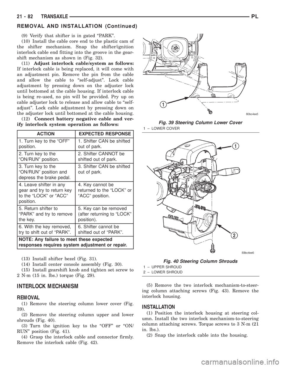
(9) Verify that shifter is in gated ªPARKº.
(10) Install the cable core end to the plastic cam of
the shifter mechanism. Snap the shifter/ignition
interlock cable end fitting into the groove in the gear-
shift mechanism as shown in (Fig. 32).
(11)Adjust interlock cable/system as follows:
If interlock cable is being replaced, it will come with
an adjustment pin. Remove the pin from the cable
and allow the cable to ªself-adjustº. Lock cable
adjustment by pressing down on the adjuster lock
until bottomed at the cable housing. If interlock cable
is being re-used, no pin will be provided. Pry up on
cable adjuster lock to release and allow cable to ªself-
adjustº. Lock cable adjustment by pressing down on
the adjuster lock until bottomed at the cable housing.
(12)Connect battery negative cable and ver-
ify interlock system operation as follows:
(13) Install shifter bezel (Fig. 31).
(14) Install center console assembly (Fig. 30).
(15) Install gearshift knob and tighten set screw to
2 N´m (15 in. lbs.) torque (Fig. 29).
INTERLOCK MECHANISM
REMOVAL
(1) Remove the steering column lower cover (Fig.
39).
(2) Remove the steering column upper and lower
shrouds (Fig. 40).
(3) Turn the ignition key to the ªOFFº or ªON/
RUNº position (Fig. 41).
(4) Grasp the interlock cable and connector firmly.
Remove the interlock cable (Fig. 42).(5) Remove the two interlock mechanism-to-steer-
ing column attaching screws (Fig. 43). Remove the
interlock housing.INSTALLATION
(1) Position the interlock housing at steering col-
umn. Install the two interlock mechanism-to-steering
column attaching screws. Torque screws to 3 N´m (21
in. lbs.).
(2) Snap the interlock cable into the housing.
ACTION EXPECTED RESPONSE
1. Turn key to the ªOFFº
position.1. Shifter CAN be shifted
out of park.
2. Turn key to the
9ON/RUNº position.2. Shifter CANNOT be
shifted out of park.
3. Turn key to the
ªON/RUNº position and
depress the brake pedal.3. Shifter CAN be shifted
out of park.
4. Leave shifter in any
gear and try to return key
to the ªLOCKº or9ACCº
position.4. Key cannot be
returned to the ªLOCKº or
ªACCº position.
5. Return shifter to
ªPARKº and try to remove
the key.5. Key can be removed
(after returning to ªLOCKº
position).
6. With the key removed,
try to shift out of ªPARKº.6. Shifter cannot be
shifted out of ªPARKº.
NOTE: Any failure to meet these expected
responses requires system adjustment or repair.
Fig. 39 Steering Column Lower Cover
1 ± LOWER COVER
Fig. 40 Steering Column Shrouds
1 ± UPPER SHROUD
2 ± LOWER SHROUD
21 - 82 TRANSAXLEPL
REMOVAL AND INSTALLATION (Continued)
Page 996 of 1285
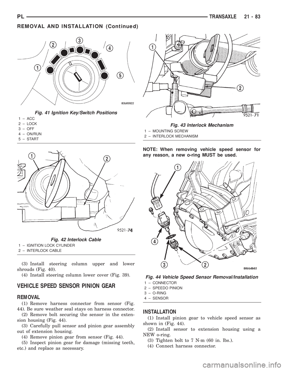
(3) Install steering column upper and lower
shrouds (Fig. 40).
(4) Install steering column lower cover (Fig. 39).
VEHICLE SPEED SENSOR PINION GEAR
REMOVAL
(1) Remove harness connector from sensor (Fig.
44). Be sure weather seal stays on harness connector.
(2) Remove bolt securing the sensor in the exten-
sion housing (Fig. 44).
(3) Carefully pull sensor and pinion gear assembly
out of extension housing.
(4) Remove pinion gear from sensor (Fig. 44).
(5) Inspect pinion gear for damage (missing teeth,
etc.) and replace as necessary.NOTE: When removing vehicle speed sensor for
any reason, a new o-ring MUST be used.
INSTALLATION
(1) Install pinion gear to vehicle speed sensor as
shown in (Fig. 44).
(2) Install sensor to extension housing using a
NEW o-ring.
(3) Tighten bolt to 7 N´m (60 in. lbs.).
(4) Connect harness connector.
Fig. 41 Ignition Key/Switch Positions
1 ± ACC
2 ± LOCK
3 ± OFF
4 ± ON/RUN
5±START
Fig. 42 Interlock Cable
1 ± IGNITION LOCK CYLINDER
2 ± INTERLOCK CABLE
Fig. 43 Interlock Mechanism
1 ± MOUNTING SCREW
2 ± INTERLOCK MECHANISM
Fig. 44 Vehicle Speed Sensor Removal/Installation
1 ± CONNECTOR
2 ± SPEEDO PINION
3 ± O-RING
4 ± SENSOR
PLTRANSAXLE 21 - 83
REMOVAL AND INSTALLATION (Continued)