2000 DODGE NEON key
[x] Cancel search: keyPage 771 of 1285
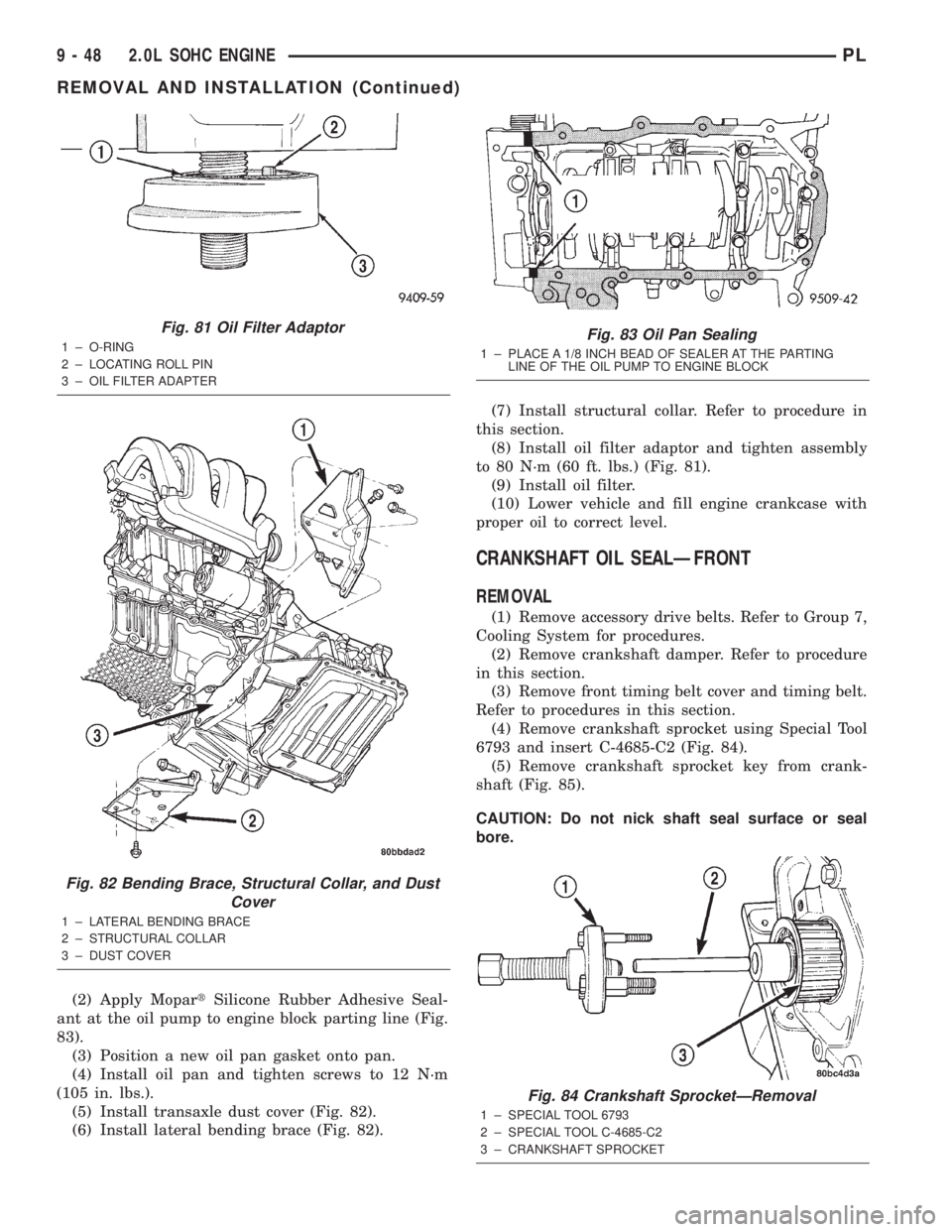
(2) Apply MopartSilicone Rubber Adhesive Seal-
ant at the oil pump to engine block parting line (Fig.
83).
(3) Position a new oil pan gasket onto pan.
(4) Install oil pan and tighten screws to 12 N´m
(105 in. lbs.).
(5) Install transaxle dust cover (Fig. 82).
(6) Install lateral bending brace (Fig. 82).(7) Install structural collar. Refer to procedure in
this section.
(8) Install oil filter adaptor and tighten assembly
to 80 N´m (60 ft. lbs.) (Fig. 81).
(9) Install oil filter.
(10) Lower vehicle and fill engine crankcase with
proper oil to correct level.
CRANKSHAFT OIL SEALÐFRONT
REMOVAL
(1) Remove accessory drive belts. Refer to Group 7,
Cooling System for procedures.
(2) Remove crankshaft damper. Refer to procedure
in this section.
(3) Remove front timing belt cover and timing belt.
Refer to procedures in this section.
(4) Remove crankshaft sprocket using Special Tool
6793 and insert C-4685-C2 (Fig. 84).
(5) Remove crankshaft sprocket key from crank-
shaft (Fig. 85).
CAUTION: Do not nick shaft seal surface or seal
bore.
Fig. 81 Oil Filter Adaptor
1 ± O-RING
2 ± LOCATING ROLL PIN
3 ± OIL FILTER ADAPTER
Fig. 82 Bending Brace, Structural Collar, and Dust
Cover
1 ± LATERAL BENDING BRACE
2 ± STRUCTURAL COLLAR
3 ± DUST COVER
Fig. 83 Oil Pan Sealing
1 ± PLACE A 1/8 INCH BEAD OF SEALER AT THE PARTING
LINE OF THE OIL PUMP TO ENGINE BLOCK
Fig. 84 Crankshaft SprocketÐRemoval
1 ± SPECIAL TOOL 6793
2 ± SPECIAL TOOL C-4685-C2
3 ± CRANKSHAFT SPROCKET
9 - 48 2.0L SOHC ENGINEPL
REMOVAL AND INSTALLATION (Continued)
Page 772 of 1285
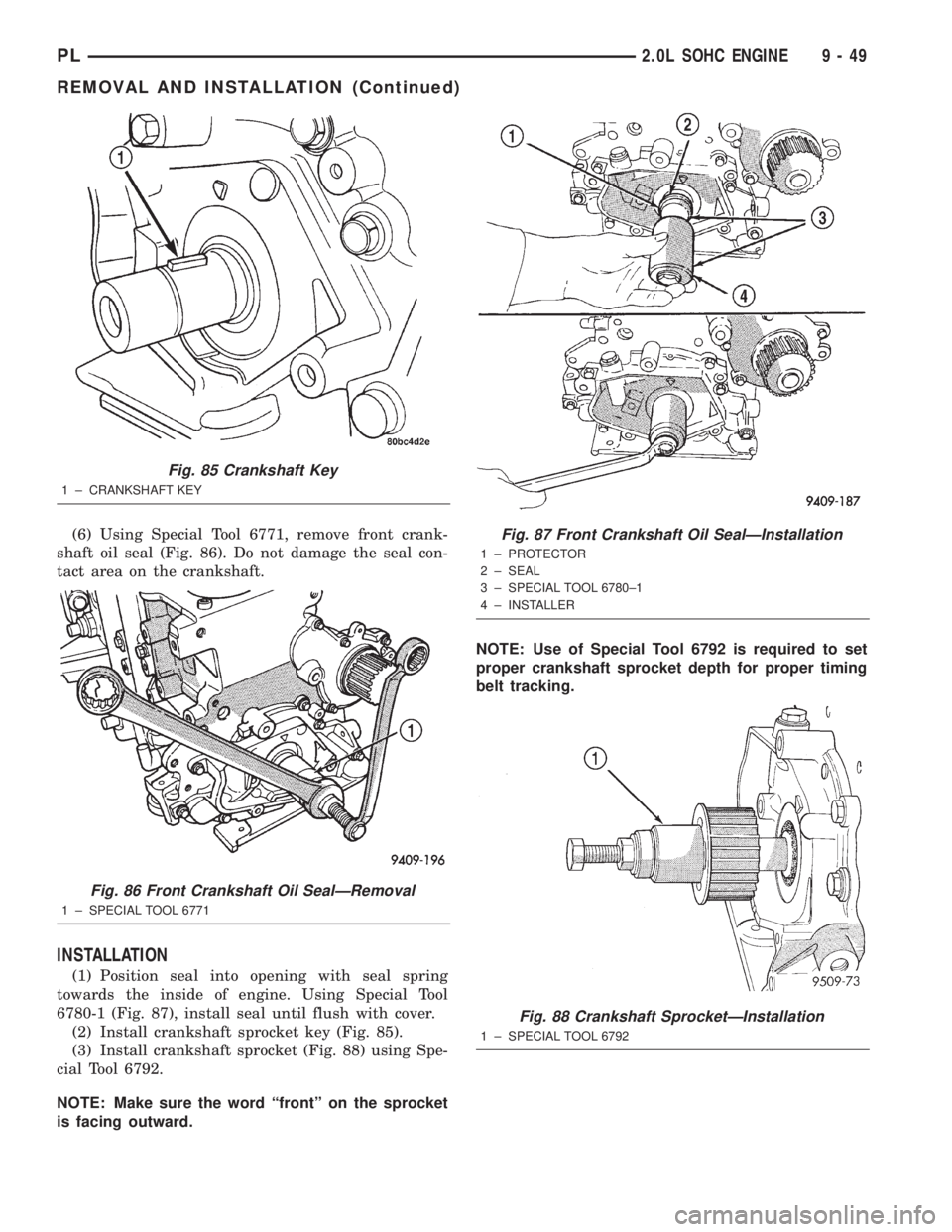
(6) Using Special Tool 6771, remove front crank-
shaft oil seal (Fig. 86). Do not damage the seal con-
tact area on the crankshaft.
INSTALLATION
(1) Position seal into opening with seal spring
towards the inside of engine. Using Special Tool
6780-1 (Fig. 87), install seal until flush with cover.
(2) Install crankshaft sprocket key (Fig. 85).
(3) Install crankshaft sprocket (Fig. 88) using Spe-
cial Tool 6792.
NOTE: Make sure the word ªfrontº on the sprocket
is facing outward.NOTE: Use of Special Tool 6792 is required to set
proper crankshaft sprocket depth for proper timing
belt tracking.
Fig. 85 Crankshaft Key
1 ± CRANKSHAFT KEY
Fig. 86 Front Crankshaft Oil SealÐRemoval
1 ± SPECIAL TOOL 6771
Fig. 87 Front Crankshaft Oil SealÐInstallation
1 ± PROTECTOR
2 ± SEAL
3 ± SPECIAL TOOL 6780±1
4 ± INSTALLER
Fig. 88 Crankshaft SprocketÐInstallation
1 ± SPECIAL TOOL 6792
PL2.0L SOHC ENGINE 9 - 49
REMOVAL AND INSTALLATION (Continued)
Page 829 of 1285
FUEL TUBES/LINES/HOSES AND CLAMPS
OPERATION
Also refer to Quick-Connect Fittings.
WARNING: THE FUEL SYSTEM IS UNDER A CON-
STANT PRESSURE (EVEN WITH THE ENGINE OFF).
BEFORE SERVICING ANY FUEL SYSTEM HOSES,
FITTINGS OR LINES, THE FUEL SYSTEM PRES-
SURE MUST BE RELEASED. REFER TO THE FUEL
SYSTEM PRESSURE RELEASE PROCEDURE IN
THIS GROUP.
Inspect all hose connections such as clamps, cou-
plings and fittings to make sure they are secure and
leaks are not present. The component should be
replaced immediately if there is any evidence of deg-
radation that could result in failure.
Never attempt to repair a plastic fuel line/tube.
Replace as necessary.
Avoid contact of any fuel tubes/hoses with other
vehicle components that could cause abrasions or
scuffing. Be sure that the plastic fuel lines/tubes areproperly routed to prevent pinching and to avoid heat
sources.
The lines/tubes/hoses used on fuel injected vehicles
are of a special construction. This is due to the
higher fuel pressures and the possibility of contami-
nated fuel in this system. If it is necessary to replace
these lines/tubes/hoses, only those marked EFM/EFI
may be used.
If equipped:The hose clamps used to secure rub-
ber hoses on fuel injected vehicles are of a special
rolled edge construction. This construction is used to
prevent the edge of the clamp from cutting into the
hose. Only these rolled edge type clamps may be
used in this system. All other types of clamps may
cut into the hoses and cause high-pressure fuel leaks.
Use new original equipment type hose clamps.
Tighten hose clamps to 3 N´m (25 in. lbs.) torque.
SERVICE PROCEDURES
FUEL SYSTEM PRESSURE RELEASE
PROCEDURE
(1) Remove Fuel Pump relay from Power Distribu-
tion Center (PDC). For location of relay, refer to label
on underside of PDC cover.
(2) Start and run engine until it stalls.
(3) Attempt restarting engine until it will no
longer run.
(4) Turn ignition key to OFF position.
CAUTION: Steps 1, 2, 3 and 4 must be performed to
relieve high pressure fuel from within fuel rail. Do
not attempt to use following steps to relieve this
pressure as excessive fuel will be forced into a cyl-
inder chamber.
(5) Place a rag or towel below fuel line quick-con-
nect fitting at fuel rail.
(6) Return fuel pump relay to PDC.
(7) One or more Diagnostic Trouble Codes (DTC's)
may have been stored in PCM memory due to fuel
pump relay removal. The DRB IIItscan tool must be
used to erase a DTC.
INJECTOR CONNECTOR
REMOVAL
(1) Disconnect electrical connectors at the fuel
injectors. To remove connector refer to (Fig. 8). Pull
the red colored slider away from injector (1). While
pulling the slider, depress tab (2) and remove connec-
tor (3) from injector. The factory fuel injection wiring
harness is numerically tagged (INJ 1, INJ 2, etc.) for
injector position identification. If harness is not
tagged, make note of wiring location before removal.
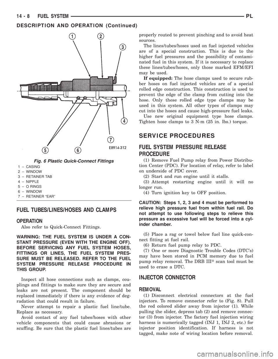
Fig. 6 Plastic Quick-Connect Fittings
1 ± CASING
2 ± WINDOW
3 ± RETAINER TAB
4 ± NIPPLE
5 ± O RINGS
6 ± WINDOW
7 ± RETAINER ªEARº
14 - 8 FUEL SYSTEMPL
DESCRIPTION AND OPERATION (Continued)
Page 843 of 1285
DESCRIPTION AND OPERATION
INJECTION SYSTEM
All engines used in this section have a sequential
Multi-Port Electronic Fuel Injection system. The MPI
system is computer regulated and provides precise
air/fuel ratios for all driving conditions. The Power-
train Control Module (PCM) operates the fuel injec-
tion system.
The PCM regulates:
²Ignition timing
²Air/fuel ratio
²Emission control devices
²Cooling fan
²Charging system
²Idle speed
²Vehicle speed control
Various sensors provide the inputs necessary for
the PCM to correctly operate these systems. In addi-
tion to the sensors, various switches also provide
inputs to the PCM.
All inputs to the PCM are converted into signals.
The PCM can adapt its programming to meet chang-
ing operating conditions.
Fuel is injected into the intake port above the
intake valve in precise metered amounts through
electrically operated injectors. The PCM fires the
injectors in a specific sequence. Under most operat-
ing conditions, the PCM maintains an air fuel ratio
of 14.7 parts air to 1 part fuel by constantly adjust-
ing injector pulse width. Injector pulse width is the
length of time the injector is open.
The PCM adjusts injector pulse width by opening
and closing the ground path to the injector. Engine
RPM (speed) and manifold absolute pressure (air
density) are the primary inputs that determine injec-
tor pulse width.
MODES OF OPERATION
OPERATION
As input signals to the PCM change, the PCM
adjusts its response to output devices. For example,
the PCM must calculate a different injector pulse
width and ignition timing for idle than it does for
Wide Open Throttle (WOT). There are several differ-
ent modes of operation that determine how the PCM
responds to the various input signals.
There are two different areas of operation, OPEN
LOOP and CLOSED LOOP.
During OPEN LOOP modes the PCM receives
input signals and responds according to preset PCM
programming. Inputs from the upstream and down-
stream heated oxygen sensors are not monitored dur-
ing OPEN LOOP modes, except for heated oxygensensor diagnostics (they are checked for shorted con-
ditions at all times).
During CLOSED LOOP modes the PCM monitors
the inputs from the upstream and downstream
heated oxygen sensors. The upstream heated oxygen
sensor input tells the PCM if the calculated injector
pulse width resulted in the ideal air-fuel ratio of 14.7
to one. By monitoring the exhaust oxygen content
through the upstream heated oxygen sensor, the
PCM can fine tune injector pulse width. Fine tuning
injector pulse width allows the PCM to achieve opti-
mum fuel economy combined with low emissions.
For the PCM to enter CLOSED LOOP operation,
the following must occur:
(1) Engine coolant temperature must be over 35ÉF.
²If the coolant is over 35É the PCM will wait 44
seconds.
²If the coolant is over 50ÉF the PCM will wait 38
seconds.
²If the coolant is over 167ÉF the PCM will wait
11 seconds.
(2) For other temperatures the PCM will interpo-
late the correct waiting time.
(3) O2 sensor must read either greater than 0.745
volts or less than 0.1 volt.
(4) The multi-port fuel injection systems has the
following modes of operation:
²Ignition switch ON (Zero RPM)
²Engine start-up
²Engine warm-up
²Cruise
²Idle
²Acceleration
²Deceleration
²Wide Open Throttle
²Ignition switch OFF
(5) The engine start-up (crank), engine warm-up,
deceleration with fuel shutoff and wide open throttle
modes are OPEN LOOP modes. Under most operat-
ing conditions, the acceleration, deceleration (with
A/C on), idle and cruise modes,with the engine at
operating temperatureare CLOSED LOOP modes.
IGNITION SWITCH ON (ZERO RPM) MODE
When the ignition switch activates the fuel injec-
tion system, the following actions occur:
²The PCM monitors the engine coolant tempera-
ture sensor and throttle position sensor input. The
PCM determines basic fuel injector pulse width from
this input.
²The PCM determines atmospheric air pressure
from the MAP sensor input to modify injector pulse
width.
When the key is in the ON position and the engine
is not running (zero rpm), the Auto Shutdown (ASD)
and fuel pump relays de-energize after approximately
14 - 22 FUEL SYSTEMPL
Page 849 of 1285
BATTERY VOLTAGEÐPCM INPUT
OPERATION
In order for the PCM to operate, it must be sup-
plied with battery voltage and ground. The PCM
monitors the direct battery feed input to determine
battery charging rate and to control the injector ini-
tial opening point. It also has back-up RAM memory
used to store Diagnostic Trouble Codes (supply work-
ing DTCs). Direct battery feed is also used to perform
key-OFF diagnostics and to supply working voltage
to the controller for OBDII.
The five and eight volt regulators are protected
from shorts to ground. This protection allows diag-
nostics to be performed should the five volt power
supply become shorted to ground at any of the sen-
sors. A short to ground in the five volt power supply
will cause a ªno-startº situation. There is a Diagnos-
tic Trouble Code (DTC) if the five-volt power supply
becomes shorted to ground. Refer to the Diagnostic
Procedures Manual for more details on any on-board
diagnostic information.
If battery voltage is low the PCM will increase
injector pulse width (period of time that the injector
is energized).
The direct battery feed to the PCM is used as a
reference point to sense battery voltage.
Effect on Fuel Injectors
Fuel injectors are rated for operation at a specific
voltage. If the voltage increases, the plunger will
open faster and further (more efficient) and con-
versely, if voltage is low the injector will be slow to
open and will not open as far. Therefore, if sensed
battery voltage drops, the PCM increases injector
pulse-width to maintain the same volume of fuel
through the injector.
Charging
The PCM uses sensed battery voltage to verify that
target charging voltage (determined by Battery Tem-
perature Sensor) is being reached. To maintain the
target charging voltage, the PCM will full field the
generator to 0.5 volt above target then turn OFF to
0.5 volt below target. This will continue to occur up
to a 100 Hz frequency, 100 times per second.
BRAKE SWITCHÐPCM INPUT
OPERATION
When the brake switch is activated, the PCM
receives an input indicating that the brakes are
being applied. The brake switch is mounted on the
brake pedal support bracket.
CAMSHAFT POSITION SENSORÐPCM INPUT
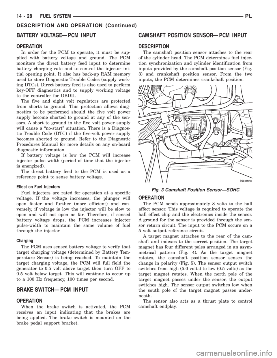
DESCRIPTION
The camshaft position sensor attaches to the rear
of the cylinder head. The PCM determines fuel injec-
tion synchronization and cylinder identification from
inputs provided by the camshaft position sensor (Fig.
3) and crankshaft position sensor. From the two
inputs, the PCM determines crankshaft position.
OPERATION
The PCM sends approximately 8 volts to the hall
affect sensor. This voltage is required to operate the
hall effect chip and the electronics inside the sensor.
A ground for the sensor is provided through the sen-
sor return circuit. The input to the PCM occurs on a
5 volt output reference circuit.
A target magnet attaches to the rear of the cam-
shaft and indexes to the correct position. The target
magnet has four different poles arranged in an asym-
metrical pattern (Fig. 4). As the target magnet
rotates, the camshaft position sensor senses the
change in polarity (Fig. 5). The sensor output switch
switches from high (5.0 volts) to low (0.5 volts) as the
target magnet rotates. When the north pole of the
target magnet passes under the sensor, the output
switches high. The sensor output switches low when
the south pole of the target magnet passes under-
neath.
The sensor also acts as a thrust plate to control
camshaft endplay.
Fig. 3 Camshaft Position SensorÐSOHC
14 - 28 FUEL SYSTEMPL
DESCRIPTION AND OPERATION (Continued)
Page 852 of 1285
OPERATION
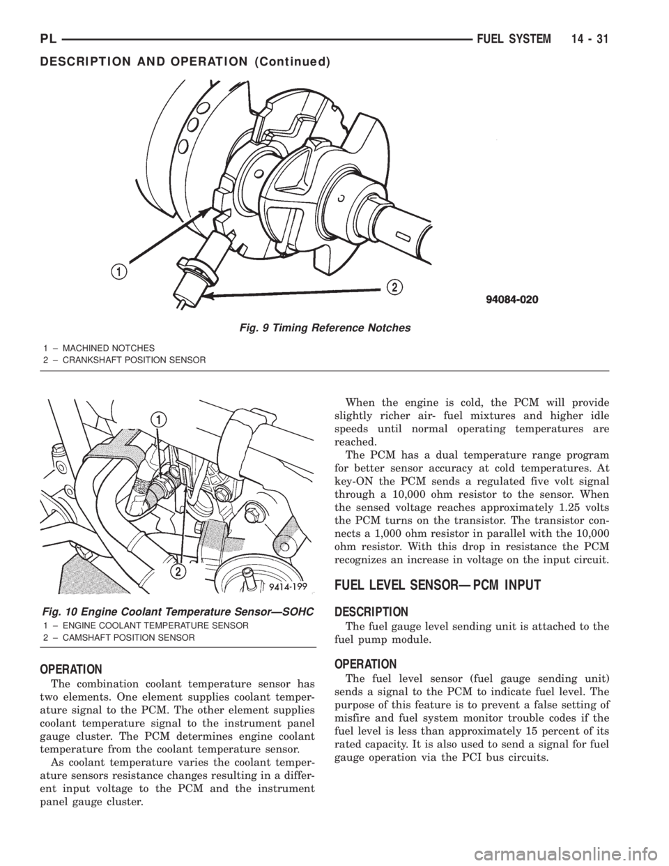
The combination coolant temperature sensor has
two elements. One element supplies coolant temper-
ature signal to the PCM. The other element supplies
coolant temperature signal to the instrument panel
gauge cluster. The PCM determines engine coolant
temperature from the coolant temperature sensor.
As coolant temperature varies the coolant temper-
ature sensors resistance changes resulting in a differ-
ent input voltage to the PCM and the instrument
panel gauge cluster.When the engine is cold, the PCM will provide
slightly richer air- fuel mixtures and higher idle
speeds until normal operating temperatures are
reached.
The PCM has a dual temperature range program
for better sensor accuracy at cold temperatures. At
key-ON the PCM sends a regulated five volt signal
through a 10,000 ohm resistor to the sensor. When
the sensed voltage reaches approximately 1.25 volts
the PCM turns on the transistor. The transistor con-
nects a 1,000 ohm resistor in parallel with the 10,000
ohm resistor. With this drop in resistance the PCM
recognizes an increase in voltage on the input circuit.
FUEL LEVEL SENSORÐPCM INPUT
DESCRIPTION
The fuel gauge level sending unit is attached to the
fuel pump module.
OPERATION
The fuel level sensor (fuel gauge sending unit)
sends a signal to the PCM to indicate fuel level. The
purpose of this feature is to prevent a false setting of
misfire and fuel system monitor trouble codes if the
fuel level is less than approximately 15 percent of its
rated capacity. It is also used to send a signal for fuel
gauge operation via the PCI bus circuits.
Fig. 9 Timing Reference Notches
1 ± MACHINED NOTCHES
2 ± CRANKSHAFT POSITION SENSOR
Fig. 10 Engine Coolant Temperature SensorÐSOHC
1 ± ENGINE COOLANT TEMPERATURE SENSOR
2 ± CAMSHAFT POSITION SENSOR
PLFUEL SYSTEM 14 - 31
DESCRIPTION AND OPERATION (Continued)
Page 856 of 1285
OPERATION
When the knock sensor detects a knock in one of
the cylinders, it sends an input signal to the PCM. In
response, the PCM retards ignition timing for all cyl-
inders by a scheduled amount.
Knock sensors contain a piezoelectric material
which sends an input voltage (signal) to the PCM. As
the intensity of the engine knock vibration increases,
the knock sensor output voltage also increases.
The voltage signal produced by the knock sensor
increases with the amplitude of vibration. The PCM
receives as an input the knock sensor voltage signal.
If the signal rises above a predetermined level, the
PCM will store that value in memory and retard
ignition timing to reduce engine knock. If the knock
sensor voltage exceeds a preset value, the PCM
retards ignition timing for all cylinders. It is not a
selective cylinder retard.
The PCM ignores knock sensor input during engine
idle conditions. Once the engine speed exceeds a
specified value, knock retard is allowed.
Knock retard uses its own short term and long
term memory program.
Long term memory stores previous detonation
information in its battery-backed RAM. The maxi-
mum authority that long term memory has over tim-
ing retard can be calibrated.
Short term memory is allowed to retard timing up
to a preset amount under all operating conditions (as
long as rpm is above the minimum rpm) except WOT.
The PCM, using short term memory, can respond
quickly to retard timing when engine knock is
detected. Short term memory is lost any time the
ignition key is turned off.
MANIFOLD ABSOLUTE PRESSURE (MAP)
SENSORÐPCM INPUT
DESCRIPTION
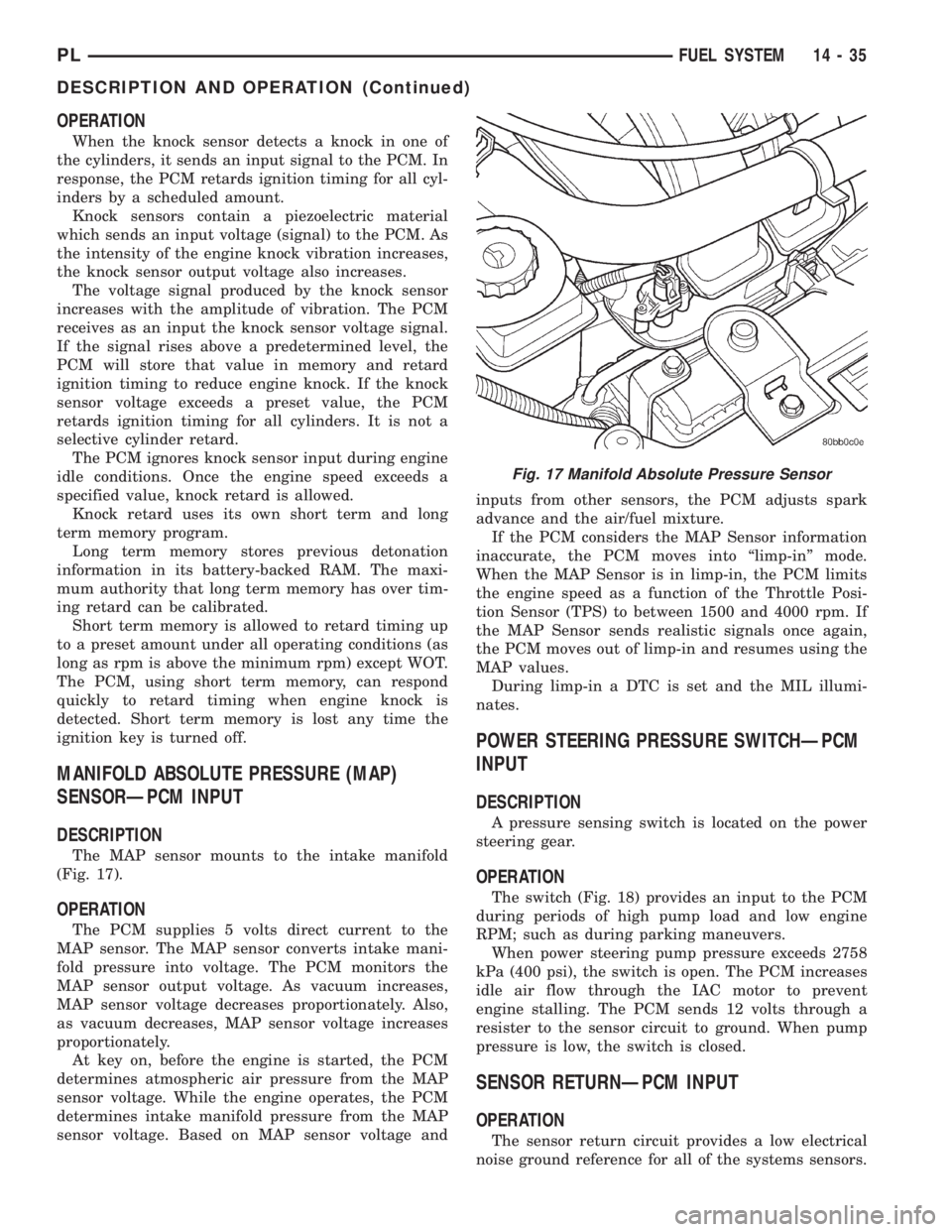
The MAP sensor mounts to the intake manifold
(Fig. 17).
OPERATION
The PCM supplies 5 volts direct current to the
MAP sensor. The MAP sensor converts intake mani-
fold pressure into voltage. The PCM monitors the
MAP sensor output voltage. As vacuum increases,
MAP sensor voltage decreases proportionately. Also,
as vacuum decreases, MAP sensor voltage increases
proportionately.
At key on, before the engine is started, the PCM
determines atmospheric air pressure from the MAP
sensor voltage. While the engine operates, the PCM
determines intake manifold pressure from the MAP
sensor voltage. Based on MAP sensor voltage andinputs from other sensors, the PCM adjusts spark
advance and the air/fuel mixture.
If the PCM considers the MAP Sensor information
inaccurate, the PCM moves into ªlimp-inº mode.
When the MAP Sensor is in limp-in, the PCM limits
the engine speed as a function of the Throttle Posi-
tion Sensor (TPS) to between 1500 and 4000 rpm. If
the MAP Sensor sends realistic signals once again,
the PCM moves out of limp-in and resumes using the
MAP values.
During limp-in a DTC is set and the MIL illumi-
nates.
POWER STEERING PRESSURE SWITCHÐPCM
INPUT
DESCRIPTION
A pressure sensing switch is located on the power
steering gear.
OPERATION
The switch (Fig. 18) provides an input to the PCM
during periods of high pump load and low engine
RPM; such as during parking maneuvers.
When power steering pump pressure exceeds 2758
kPa (400 psi), the switch is open. The PCM increases
idle air flow through the IAC motor to prevent
engine stalling. The PCM sends 12 volts through a
resister to the sensor circuit to ground. When pump
pressure is low, the switch is closed.
SENSOR RETURNÐPCM INPUT
OPERATION
The sensor return circuit provides a low electrical
noise ground reference for all of the systems sensors.
Fig. 17 Manifold Absolute Pressure Sensor
PLFUEL SYSTEM 14 - 35
DESCRIPTION AND OPERATION (Continued)
Page 862 of 1285
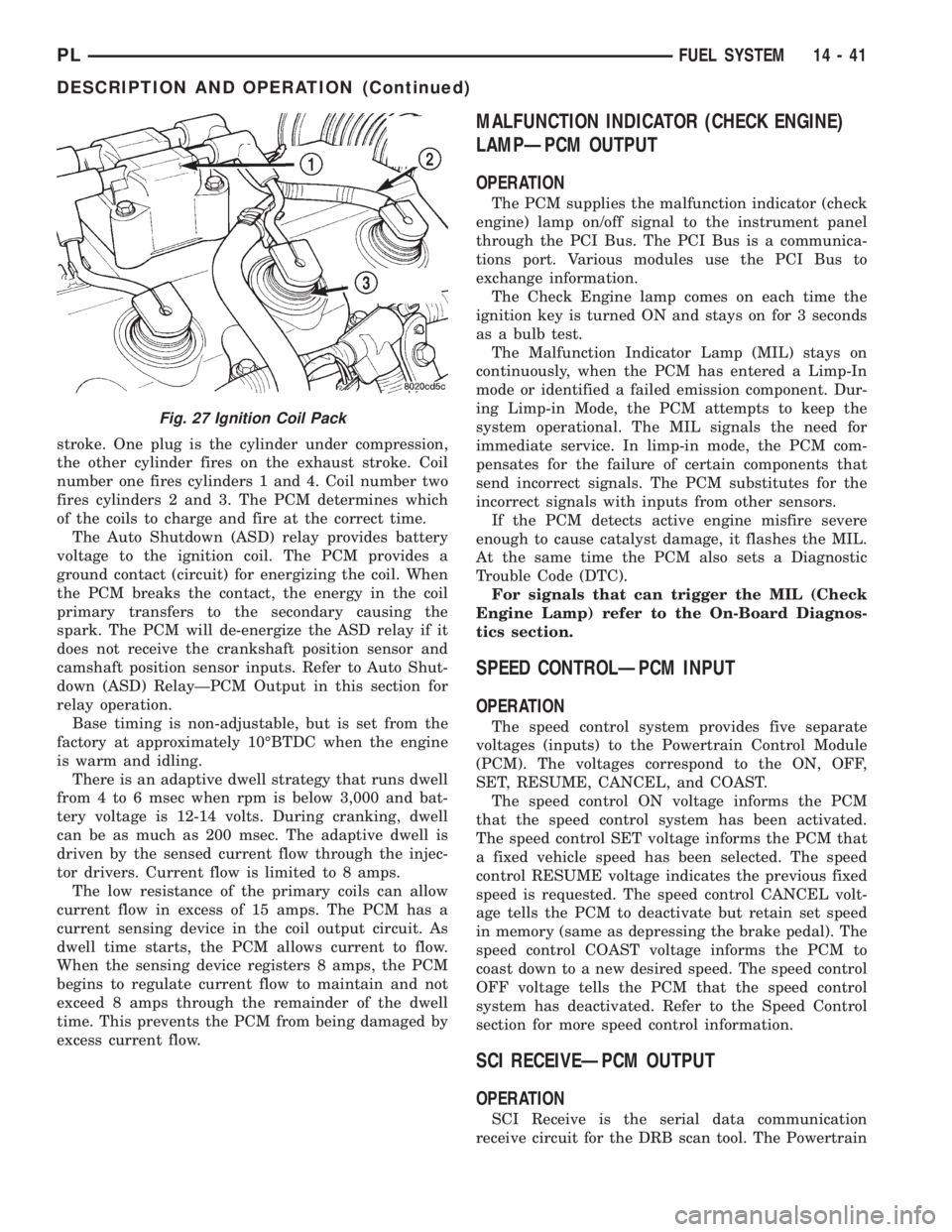
stroke. One plug is the cylinder under compression,
the other cylinder fires on the exhaust stroke. Coil
number one fires cylinders 1 and 4. Coil number two
fires cylinders 2 and 3. The PCM determines which
of the coils to charge and fire at the correct time.
The Auto Shutdown (ASD) relay provides battery
voltage to the ignition coil. The PCM provides a
ground contact (circuit) for energizing the coil. When
the PCM breaks the contact, the energy in the coil
primary transfers to the secondary causing the
spark. The PCM will de-energize the ASD relay if it
does not receive the crankshaft position sensor and
camshaft position sensor inputs. Refer to Auto Shut-
down (ASD) RelayÐPCM Output in this section for
relay operation.
Base timing is non-adjustable, but is set from the
factory at approximately 10ÉBTDC when the engine
is warm and idling.
There is an adaptive dwell strategy that runs dwell
from 4 to 6 msec when rpm is below 3,000 and bat-
tery voltage is 12-14 volts. During cranking, dwell
can be as much as 200 msec. The adaptive dwell is
driven by the sensed current flow through the injec-
tor drivers. Current flow is limited to 8 amps.
The low resistance of the primary coils can allow
current flow in excess of 15 amps. The PCM has a
current sensing device in the coil output circuit. As
dwell time starts, the PCM allows current to flow.
When the sensing device registers 8 amps, the PCM
begins to regulate current flow to maintain and not
exceed 8 amps through the remainder of the dwell
time. This prevents the PCM from being damaged by
excess current flow.
MALFUNCTION INDICATOR (CHECK ENGINE)
LAMPÐPCM OUTPUT
OPERATION
The PCM supplies the malfunction indicator (check
engine) lamp on/off signal to the instrument panel
through the PCI Bus. The PCI Bus is a communica-
tions port. Various modules use the PCI Bus to
exchange information.
The Check Engine lamp comes on each time the
ignition key is turned ON and stays on for 3 seconds
as a bulb test.
The Malfunction Indicator Lamp (MIL) stays on
continuously, when the PCM has entered a Limp-In
mode or identified a failed emission component. Dur-
ing Limp-in Mode, the PCM attempts to keep the
system operational. The MIL signals the need for
immediate service. In limp-in mode, the PCM com-
pensates for the failure of certain components that
send incorrect signals. The PCM substitutes for the
incorrect signals with inputs from other sensors.
If the PCM detects active engine misfire severe
enough to cause catalyst damage, it flashes the MIL.
At the same time the PCM also sets a Diagnostic
Trouble Code (DTC).
For signals that can trigger the MIL (Check
Engine Lamp) refer to the On-Board Diagnos-
tics section.
SPEED CONTROLÐPCM INPUT
OPERATION
The speed control system provides five separate
voltages (inputs) to the Powertrain Control Module
(PCM). The voltages correspond to the ON, OFF,
SET, RESUME, CANCEL, and COAST.
The speed control ON voltage informs the PCM
that the speed control system has been activated.
The speed control SET voltage informs the PCM that
a fixed vehicle speed has been selected. The speed
control RESUME voltage indicates the previous fixed
speed is requested. The speed control CANCEL volt-
age tells the PCM to deactivate but retain set speed
in memory (same as depressing the brake pedal). The
speed control COAST voltage informs the PCM to
coast down to a new desired speed. The speed control
OFF voltage tells the PCM that the speed control
system has deactivated. Refer to the Speed Control
section for more speed control information.
SCI RECEIVEÐPCM OUTPUT
OPERATION
SCI Receive is the serial data communication
receive circuit for the DRB scan tool. The Powertrain
Fig. 27 Ignition Coil Pack
PLFUEL SYSTEM 14 - 41
DESCRIPTION AND OPERATION (Continued)