2000 DODGE NEON headlamp
[x] Cancel search: headlampPage 662 of 1285
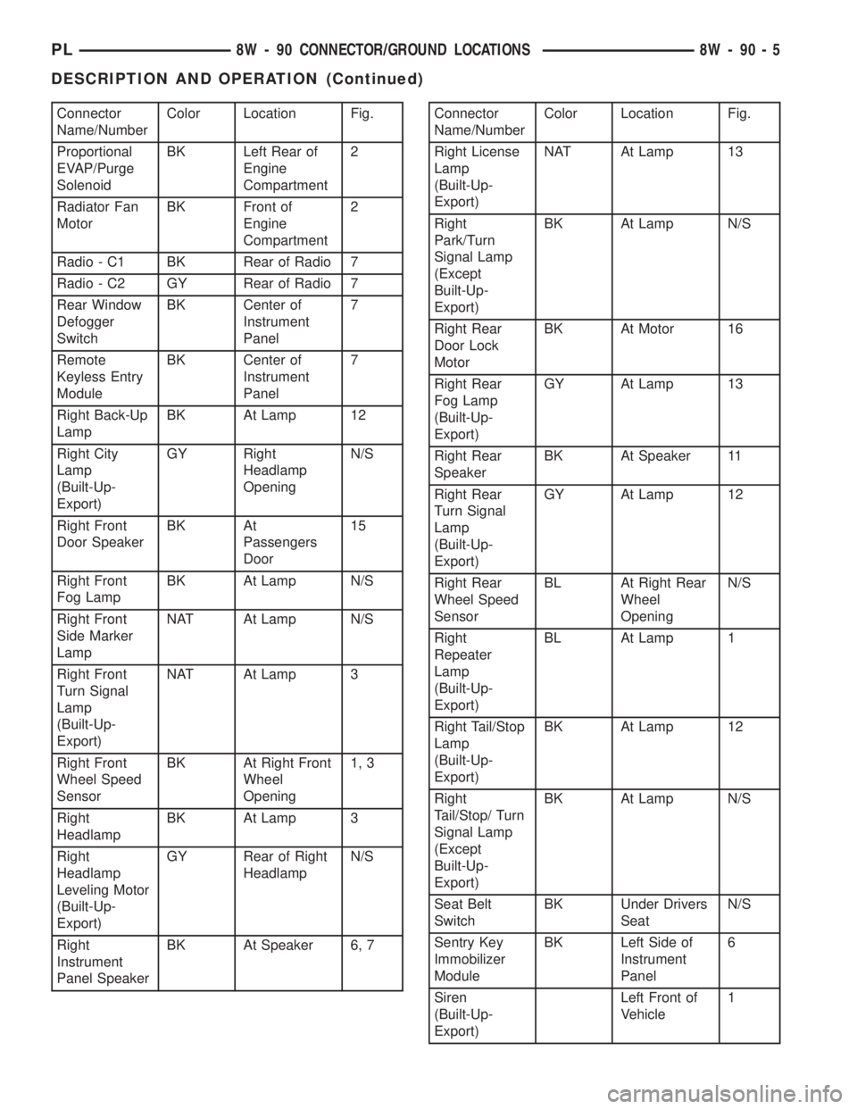
Connector
Name/NumberColor Location Fig.
Proportional
EVAP/Purge
SolenoidBK Left Rear of
Engine
Compartment2
Radiator Fan
MotorBK Front of
Engine
Compartment2
Radio - C1 BK Rear of Radio 7
Radio - C2 GY Rear of Radio 7
Rear Window
Defogger
SwitchBK Center of
Instrument
Panel7
Remote
Keyless Entry
ModuleBK Center of
Instrument
Panel7
Right Back-Up
LampBK At Lamp 12
Right City
Lamp
(Built-Up-
Export)GY Right
Headlamp
OpeningN/S
Right Front
Door SpeakerBK At
Passengers
Door15
Right Front
Fog LampBK At Lamp N/S
Right Front
Side Marker
LampNAT At Lamp N/S
Right Front
Turn Signal
Lamp
(Built-Up-
Export)NAT At Lamp 3
Right Front
Wheel Speed
SensorBK At Right Front
Wheel
Opening1, 3
Right
HeadlampBK At Lamp 3
Right
Headlamp
Leveling Motor
(Built-Up-
Export)GY Rear of Right
HeadlampN/S
Right
Instrument
Panel SpeakerBK At Speaker 6, 7Connector
Name/NumberColor Location Fig.
Right License
Lamp
(Built-Up-
Export)NAT At Lamp 13
Right
Park/Turn
Signal Lamp
(Except
Built-Up-
Export)BK At Lamp N/S
Right Rear
Door Lock
MotorBK At Motor 16
Right Rear
Fog Lamp
(Built-Up-
Export)GY At Lamp 13
Right Rear
SpeakerBK At Speaker 11
Right Rear
Turn Signal
Lamp
(Built-Up-
Export)GY At Lamp 12
Right Rear
Wheel Speed
SensorBL At Right Rear
Wheel
OpeningN/S
Right
Repeater
Lamp
(Built-Up-
Export)BL At Lamp 1
Right Tail/Stop
Lamp
(Built-Up-
Export)BK At Lamp 12
Right
Tail/Stop/ Turn
Signal Lamp
(Except
Built-Up-
Export)BK At Lamp N/S
Seat Belt
SwitchBK Under Drivers
SeatN/S
Sentry Key
Immobilizer
ModuleBK Left Side of
Instrument
Panel6
Siren
(Built-Up-
Export)Left Front of
Vehicle1
PL8W - 90 CONNECTOR/GROUND LOCATIONS 8W - 90 - 5
DESCRIPTION AND OPERATION (Continued)
Page 678 of 1285
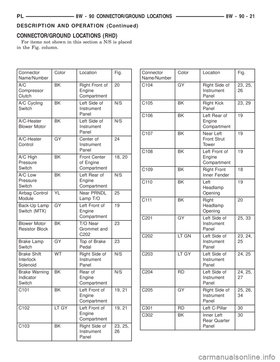
CONNECTOR/GROUND LOCATIONS (RHD)
For items not shown in this section a N/S is placed
in the Fig. column.
Connector
Name/NumberColor Location Fig.
A/C
Compressor
ClutchBK Right Front of
Engine
Compartment20
A/C Cycling
SwitchBK Left Side of
Instrument
PanelN/S
A/C-Heater
Blower MotorBK Left Side of
Instrument
PanelN/S
A/C-Heater
ControlGY Center of
Instrument
Panel24
A/C High
Pressure
SwitchBK Front Center
of Engine
Compartment18, 20
A/C Low
Pressure
SwitchBK Left Rear of
Engine
CompartmentN/S
Airbag Control
ModuleYL Near PRNDL
Lamp T/O25
Back-Up Lamp
Switch (MTX)GY Left Front of
Engine
Compartment19
Blower Motor
Resistor BlockBK T/O Near
Grommet and
C20223
Brake Lamp
SwitchGY Top of Brake
Pedal23
Brake Shift
Interlock
SolenoidWT Right Side of
Instrument
PanelN/S
Brake Warning
Indicator
SwitchBK Rear of
Engine
CompartmentN/S
C101 BK Left Front of
Engine
Compartment19, 21
C102 LT GY Left Front of
Engine
Compartment19, 21
C103 BK Right Side of
Instrument
Panel23, 25,
26Connector
Name/NumberColor Location Fig.
C104 GY Right Side of
Instrument
Panel23, 25,
26
C105 BK Right Kick
Panel23, 29
C106 BK Left Rear of
Engine
Compartment19
C107 BK Near Left
Front Strut
Tower19
C108 BK Left Front of
Engine
Compartment19
C109 BK Right Front
Inner Fender18
C110 BK Left
Headlamp
Opening19
C111 BK Right
Headlamp
Opening20
C201 GY Left Side of
Instrument
Panel25, 33
C202 LT GN Left Side of
Instrument
Panel23, 24,
25
C203 LT GY Left Side of
Instrument
Panel24, 25
C204 RD Left Side of
Instrument
Panel24, 25,
27
C205 GY Right Side of
Instrument
Panel25, 26,
34
C301 RD Left C-Pillar 30
C302 BK Inner Left
Rear Quarter
Panel30
PL8W - 90 CONNECTOR/GROUND LOCATIONS 8W - 90 - 21
DESCRIPTION AND OPERATION (Continued)
Page 680 of 1285
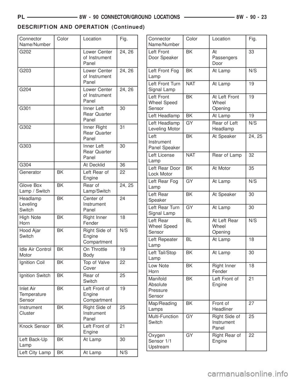
Connector
Name/NumberColor Location Fig.
G202 Lower Center
of Instrument
Panel24, 26
G203 Lower Center
of Instrument
Panel24, 26
G204 Lower Center
of Instrument
Panel24, 26
G301 Inner Left
Rear Quarter
Panel30
G302 Inner Right
Rear Quarter
Panel31
G303 Inner Left
Rear Quarter
Panel30
G304 At Decklid 36
Generator BK Left Rear of
Engine22
Glove Box
Lamp / SwitchBK Rear of
Lamp/Switch24, 25
Headlamp
Leveling
SwitchBK Center of
Instrument
Panel24
High Note
HornBK Right Inner
Fender18
Hood Ajar
SwitchBK Right Side of
Engine
CompartmentN/S
Idle Air Control
MotorBK On Throttle
Body19
Ignition Coil BK Top of Valve
Cover22
Ignition Switch BK Rear of
Switch25
Inlet Air
Temperature
SensorBK Left Front of
Engine
Compartment19
Instrument
ClusterBK Right Side of
Instrument
Panel25
Knock Sensor BK Left Front of
Engine21
Left Back-Up
LampBK At Lamp 30
Left City Lamp BK At Lamp N/SConnector
Name/NumberColor Location Fig.
Left Front
Door SpeakerBK At
Passengers
Door33
Left Front Fog
LampBK At Lamp N/S
Left Front Turn
Signal LampNAT At Lamp 19
Left Front
Wheel Speed
SensorBK At Left Front
Wheel
Opening19
Left Headlamp BK At Lamp 19
Left Headlamp
Leveling MotorGY Rear of Left
HeadlampN/S
Left
Instrument
Panel SpeakerBK At Speaker 24, 25
Left License
LampNAT Rear of Lamp 32
Left Rear Door
Lock MotorBK At Motor 35
Left Rear Fog
LampGY At Lamp N/S
Left Rear
SpeakerBK At Speaker 30
Left Rear Turn
Signal LampGY At Lamp 30
Left Rear
Wheel Speed
SensorBL At Left Rear
Wheel
OpeningN/S
Left Repeater
LampBL At Lamp 18
Left Tail/Stop
LampBK At Lamp 30
Low Note
HornBK Right Inner
Fender18
Manifold
Absolute
Pressure
SensorBK Left Front of
Engine21
Map/Reading
LampsBK Front of
Headliner27
Multi-Function
SwitchGY Right Side of
Instrument
Panel25
Oxygen
Sensor 1/1
UpstreamGY Right Rear of
Engine22
PL8W - 90 CONNECTOR/GROUND LOCATIONS 8W - 90 - 23
DESCRIPTION AND OPERATION (Continued)
Page 681 of 1285
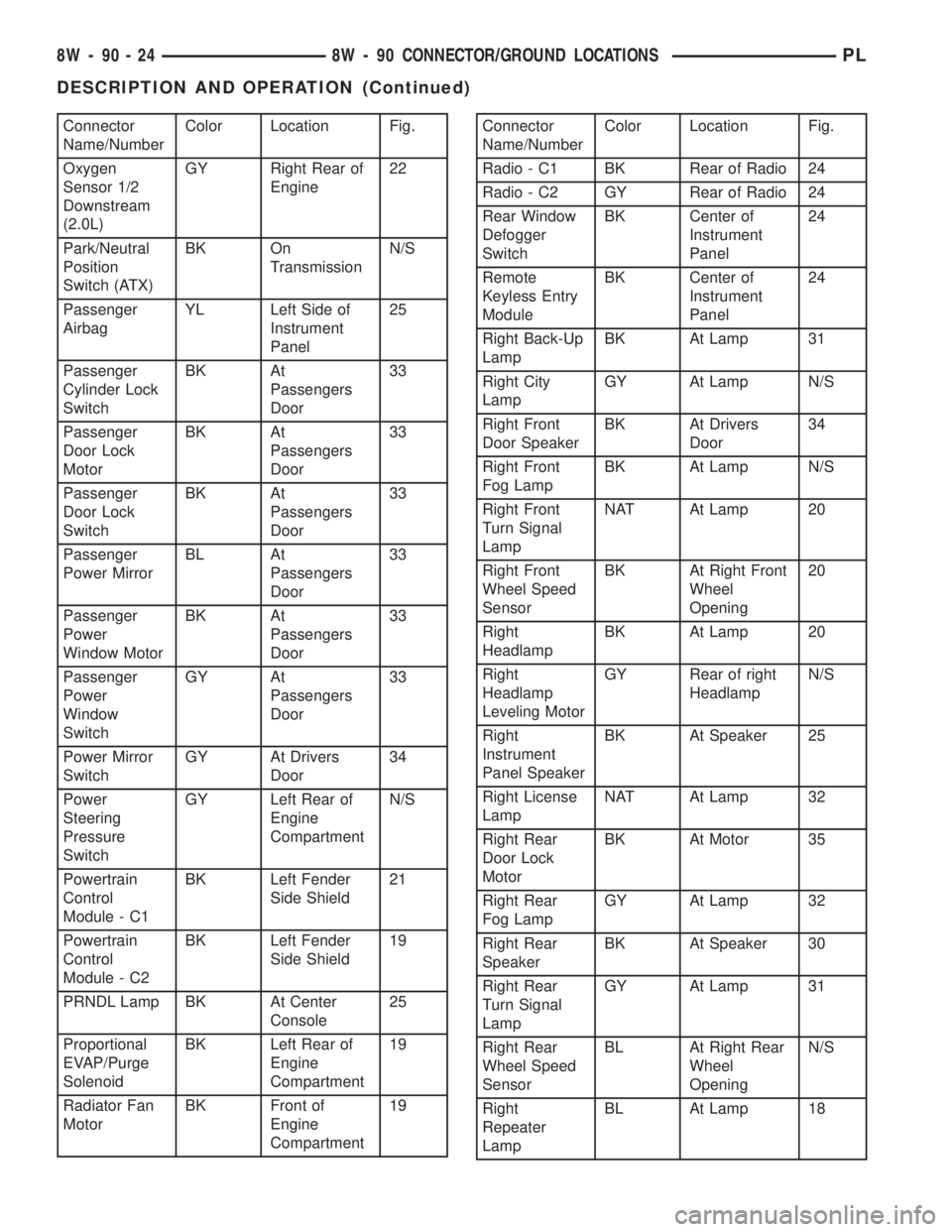
Connector
Name/NumberColor Location Fig.
Oxygen
Sensor 1/2
Downstream
(2.0L)GY Right Rear of
Engine22
Park/Neutral
Position
Switch (ATX)BK On
TransmissionN/S
Passenger
AirbagYL Left Side of
Instrument
Panel25
Passenger
Cylinder Lock
SwitchBK At
Passengers
Door33
Passenger
Door Lock
MotorBK At
Passengers
Door33
Passenger
Door Lock
SwitchBK At
Passengers
Door33
Passenger
Power MirrorBL At
Passengers
Door33
Passenger
Power
Window MotorBK At
Passengers
Door33
Passenger
Power
Window
SwitchGY At
Passengers
Door33
Power Mirror
SwitchGY At Drivers
Door34
Power
Steering
Pressure
SwitchGY Left Rear of
Engine
CompartmentN/S
Powertrain
Control
Module - C1BK Left Fender
Side Shield21
Powertrain
Control
Module - C2BK Left Fender
Side Shield19
PRNDL Lamp BK At Center
Console25
Proportional
EVAP/Purge
SolenoidBK Left Rear of
Engine
Compartment19
Radiator Fan
MotorBK Front of
Engine
Compartment19Connector
Name/NumberColor Location Fig.
Radio - C1 BK Rear of Radio 24
Radio - C2 GY Rear of Radio 24
Rear Window
Defogger
SwitchBK Center of
Instrument
Panel24
Remote
Keyless Entry
ModuleBK Center of
Instrument
Panel24
Right Back-Up
LampBK At Lamp 31
Right City
LampGY At Lamp N/S
Right Front
Door SpeakerBK At Drivers
Door34
Right Front
Fog LampBK At Lamp N/S
Right Front
Turn Signal
LampNAT At Lamp 20
Right Front
Wheel Speed
SensorBK At Right Front
Wheel
Opening20
Right
HeadlampBK At Lamp 20
Right
Headlamp
Leveling MotorGY Rear of right
HeadlampN/S
Right
Instrument
Panel SpeakerBK At Speaker 25
Right License
LampNAT At Lamp 32
Right Rear
Door Lock
MotorBK At Motor 35
Right Rear
Fog LampGY At Lamp 32
Right Rear
SpeakerBK At Speaker 30
Right Rear
Turn Signal
LampGY At Lamp 31
Right Rear
Wheel Speed
SensorBL At Right Rear
Wheel
OpeningN/S
Right
Repeater
LampBL At Lamp 18
8W - 90 - 24 8W - 90 CONNECTOR/GROUND LOCATIONSPL
DESCRIPTION AND OPERATION (Continued)
Page 698 of 1285
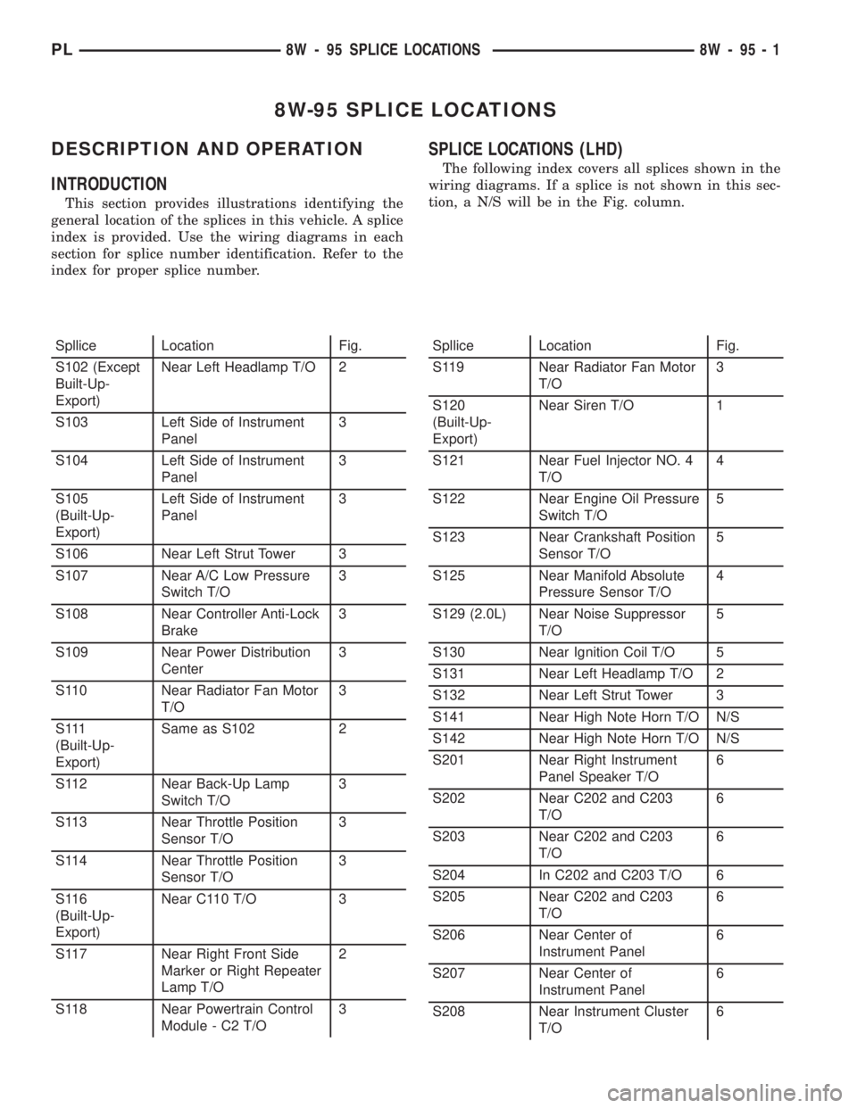
8W-95 SPLICE LOCATIONS
DESCRIPTION AND OPERATION
INTRODUCTION
This section provides illustrations identifying the
general location of the splices in this vehicle. A splice
index is provided. Use the wiring diagrams in each
section for splice number identification. Refer to the
index for proper splice number.
SPLICE LOCATIONS (LHD)
The following index covers all splices shown in the
wiring diagrams. If a splice is not shown in this sec-
tion, a N/S will be in the Fig. column.
Spllice Location Fig.
S102 (Except
Built-Up-
Export)Near Left Headlamp T/O 2
S103 Left Side of Instrument
Panel3
S104 Left Side of Instrument
Panel3
S105
(Built-Up-
Export)Left Side of Instrument
Panel3
S106 Near Left Strut Tower 3
S107 Near A/C Low Pressure
Switch T/O3
S108 Near Controller Anti-Lock
Brake3
S109 Near Power Distribution
Center3
S110 Near Radiator Fan Motor
T/O3
S 111
(Built-Up-
Export)Same as S102 2
S112 Near Back-Up Lamp
Switch T/O3
S113 Near Throttle Position
Sensor T/O3
S114 Near Throttle Position
Sensor T/O3
S116
(Built-Up-
Export)Near C110 T/O 3
S117 Near Right Front Side
Marker or Right Repeater
Lamp T/O2
S118 Near Powertrain Control
Module - C2 T/O3Spllice Location Fig.
S119 Near Radiator Fan Motor
T/O3
S120
(Built-Up-
Export)Near Siren T/O 1
S121 Near Fuel Injector NO. 4
T/O4
S122 Near Engine Oil Pressure
Switch T/O5
S123 Near Crankshaft Position
Sensor T/O5
S125 Near Manifold Absolute
Pressure Sensor T/O4
S129 (2.0L) Near Noise Suppressor
T/O5
S130 Near Ignition Coil T/O 5
S131 Near Left Headlamp T/O 2
S132 Near Left Strut Tower 3
S141 Near High Note Horn T/O N/S
S142 Near High Note Horn T/O N/S
S201 Near Right Instrument
Panel Speaker T/O6
S202 Near C202 and C203
T/O6
S203 Near C202 and C203
T/O6
S204 In C202 and C203 T/O 6
S205 Near C202 and C203
T/O6
S206 Near Center of
Instrument Panel6
S207 Near Center of
Instrument Panel6
S208 Near Instrument Cluster
T/O6
PL8W - 95 SPLICE LOCATIONS 8W - 95 - 1
Page 710 of 1285
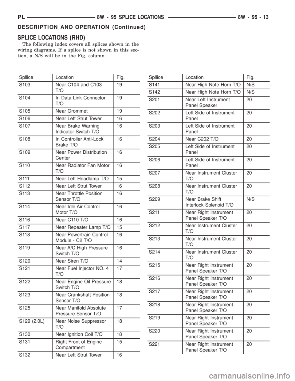
SPLICE LOCATIONS (RHD)
The following index covers all splices shown in the
wiring diagrams. If a splice is not shown in this sec-
tion, a N/S will be in the Fig. column.
Spllice Location Fig.
S103 Near C104 and C103
T/O19
S104 In Data Link Connector
T/O19
S105 Near Grommet 19
S106 Near Left Strut Tower 16
S107 Near Brake Warning
Indicator Switch T/O16
S108 In Controller Anti-Lock
Brake T/O16
S109 Near Power Distribution
Center16
S110 Near Radiator Fan Motor
T/O16
S111 Near Left Headlamp T/O 15
S112 Near Left Strut Tower 16
S113 Near Throttle Position
Sensor T/O16
S114 Near Idle Air Control
Motor T/O16
S116 Near C110 T/O 16
S117 Near Repeater Lamp T/O 15
S118 Near Powertrain Control
Module - C2 T/O16
S119 Near A/C High Pressure
Switch T/O16
S120 Near Siren T/O 14
S121 Near Fuel Injector NO. 4
T/O17
S122 Near Engine Oil Pressure
Switch T/O18
S123 Near Crankshaft Position
Sensor T/O18
S125 Near Manifold Absolute
Pressure Sensor T/O17
S129 (2.0L) Near Noise Suppressor
T/O18
S130 Near Ignition Coil T/O 18
S131 Right Front of Engine
Compartment15
S132 Near Left Strut Tower 16Spllice Location Fig.
S141 Near High Note Horn T/O N/S
S142 Near High Note Horn T/O N/S
S201 Near Left Instrument
Panel Speaker20
S202 Left Side of Instrument
Panel20
S203 Left Side of Instrument
Panel20
S204 Near C202 T/O 20
S205 Left Side of Instrument
Panel20
S206 Left Side of Instrument
Panel20
S207 Near Instrument Cluster
T/O20
S208 Near Instrument Cluster
T/O20
S209 Near Brake Shift
Interlock Solenoid T/ON/S
S211 Near Right Instrument
Panel Speaker T/O20
S212 Near Instrument Cluster
T/O20
S213 Near Instrument Cluster
T/O20
S214 Near Instrument Cluster
T/O20
S215 Near Right Instrument
Panel Speaker T/O20
S216 Near Right Instrument
Panel Speaker T/O20
S217 Near Right Instrument
Panel Speaker T/O20
S218 Near Right Instrument
Panel Speaker T/O20
S219 Near Right Instrument
Panel Speaker T/O20
S220 Near Right Instrument
Panel Speaker T/O20
S221 Near Right Instrument
Panel Speaker T/O20
PL8W - 95 SPLICE LOCATIONS 8W - 95 - 13
DESCRIPTION AND OPERATION (Continued)
Page 1145 of 1285
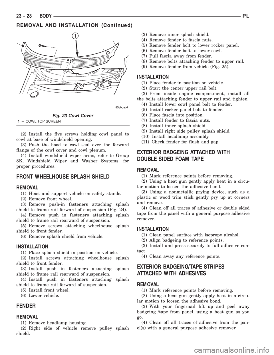
(2) Install the five screws holding cowl panel to
cowl at base of windshield opening.
(3) Push the hood to cowl seal over the forward
flange of the cowl cover and cowl plenum.
(4) Install windshield wiper arms, refer to Group
8K, Windshield Wiper and Washer Systems, for
proper procedures.
FRONT WHEELHOUSE SPLASH SHIELD
REMOVAL
(1) Hoist and support vehicle on safety stands.
(2) Remove front wheel.
(3) Remove push-in fasteners attaching splash
shield to frame rail forward of suspension (Fig. 24).
(4) Remove push in fasteners attaching splash
shield to frame rail rearward of suspension.
(5) Remove screws attaching wheelhouse splash
shield to front fender.
(6) Remove splash shield from vehicle.
INSTALLATION
(1) Place splash shield in position on vehicle.
(2) Install screws attaching wheelhouse splash
shield to front fender.
(3) Install push in fasteners attaching splash
shield to frame rail rearward of suspension.
(4) Install push in fasteners attaching splash
shield to frame rail forward of suspension.
(5) Install front wheel.
(6) Lower vehicle.
FENDER
REMOVAL
(1) Remove headlamp housing.
(2) Right side of vehicle remove pulley splash
shield.(3) Remove inner splash shield.
(4) Remove fender to fascia nuts.
(5) Remove fender bolt to lower rocker panel.
(6) Remove fender bolt to lower cowl.
(7) Pull fascia away from fender.
(8) Remove bolts attaching fender to upper rail.
(9) Remove fender from vehicle (Fig. 25).
INSTALLATION
(1) Place fender in position on vehicle.
(2) Start the center upper rail bolt.
(3) From inside engine compartment, install all
the bolts attaching fender to upper rail and tighten.
(4) Install lower cowl panel bolt to fender.
(5) Install rocker panel bolt to fender.
(6) Place fascia into position.
(7) Install fender to fascia nuts.
(8) Install inner splash shield.
(9) Install right side pulley splash shield.
(10) Install headlamp assembly.
(11) Check fender for flush and gap.
EXTERIOR BADGEING ATTACHED WITH
DOUBLE SIDED FOAM TAPE
REMOVAL
(1) Mark reference points before removing.
(2) Using a heat gun gently apply heat in a circu-
lar motion to loosen the adhesive bond.
(3) Using a nonmetallic prying device, such as a
plastic or wood trim stick gently pry up at corners
and remove.
(4) Clean off all traces of adhesive or double sided
tape from the panel with a general purpose adhesive
remover.
INSTALLATION
(1) Clean panel surface with isopropy alcohol.
(2) Align badgeing to reference points.
(3) Install and press securely to full adhesive con-
tact
(4) Clean away any reference points.
EXTERIOR BADGEING/TAPE STRIPES
ATTACHED WITH ADHESIVES
REMOVAL
(1) Mark reference points before removing.
(2) Using a heat gun gently apply heat in a circu-
lar motion to loosen the adhesive bond.
(3) With your fingernail lift up and peel away
badgeing /tape from panel, using a heat gun as you
go.
(4) Clean off all traces of adhesive from the pan-
el(s) with a general purpose adhesive remover.
Fig. 23 Cowl Cover
1 ± COWL TOP SCREEN
23 - 28 BODYPL
REMOVAL AND INSTALLATION (Continued)