2000 DODGE NEON ignition
[x] Cancel search: ignitionPage 382 of 1285
POWER MIRRORS
TABLE OF CONTENTS
page page
DESCRIPTION AND OPERATION
INTRODUCTION..........................1
DIAGNOSIS AND TESTING
MIRROR SWITCH TEST....................1
POWER MIRROR MOTOR..................2
REMOVAL AND INSTALLATION
INSIDE MIRROR/READING LAMPS
ASSEMBLY.............................2INSIDE MIRROR/READING LAMPS
BULB/LENS............................3
MIRROR SWITCH.........................3
POWER MIRROR ASSEMBLY................3
DESCRIPTION AND OPERATION
INTRODUCTION
Electrically operated power mirrors are available
on all car lines. The mirrors are controlled by a sin-
gle switch assembly located on the driver's door trim
panel. The push button rocker switch uses L (left)
and R (right) for mirror selection and a button to
push for the desired direction of mirror movement.
The motors which operate the mirrors are part of
the mirror assembly and cannot be replaced sepa-
rately.
The Ignition Off Draw fuse is included in the
power mirror circuity and should be checked if the
mirrors are inoperative.
DIAGNOSIS AND TESTING
MIRROR SWITCH TEST
(1) Remove power mirror switch from mounting
position. Refer to Mirror Switch Removal and Instal-
lation in this section.
(2) Using an ohmmeter, test for continuity between
the terminals of the switch as shown in the Mirror
Switch Continuity table.
(3) If test results are not obtained as shown in the
Mirror Switch Continuity table, replace the switch.
Refer to Group 8W-Wiring Diagrams for Connector
Pin-Outs and Circuit Diagrams.
PLPOWER MIRRORS 8T - 1
Page 386 of 1285
POWER MIRRORS
TABLE OF CONTENTS
page page
GENERAL INFORMATION
INTRODUCTION..........................1
DIAGNOSIS AND TESTING
POWER FOLD AWAY MIRROR SWITCH TEST...1POWER FOLD AWAY MIRROR MOTOR........1
REMOVAL AND INSTALLATION
POWER FOLD-AWAY MIRROR SWITCH.......1
POWER FOLD-AWAY MIRROR...............2
GENERAL INFORMATION
INTRODUCTION
These vehicles may be equipped with Power Fold
Away Mirrors. The vehicle has an additional switch
in the switch pod that controls the folding function of
the mirror assembly (Fig. 1).
All vehicles are equipped with a Ignition-Off Draw
Fuse, and they are disconnected when the vehicles
are originally shipped from the factory. Disconnecting
this fuse will help prevent the battery from discharge
during storage. The fuse is located in Power Distri-
bution Center (PDC) refer to the cover for proper
location.
This fuse is included in the power mirror circuity
and should be checked if the mirrors are inoperative.
The vehicle mirror circuitry is powered from the
accessory feed circuit and protected by a 15 amp cir-
cuit breaker and power mirror relay. The relay pro-
vides for the switching of the mirror. The circuit
breaker and mirror relay are located in the inner
door panel wire harness.
DIAGNOSIS AND TESTING
POWER FOLD AWAY MIRROR SWITCH TEST
(1) Remove power mirror switch from the door
trim panel. Refer to the switch removal and installa-
tion procedure in this group.
(2) Using an ohmmeter, test for continuity between
the terminals of the switch as shown in the Power
Fold Away Mirror Switch Test (Fig. 2).
(3) If test results are not obtained as shown in
(Fig. 2), replace the switch.
Refer to Group 8W, Wiring Diagrams for a com-
plete schematic of the power mirror circuitry.
POWER FOLD AWAY MIRROR MOTOR
The power fold away mirror motor is incorporated
into the mirror assembly. If the motor proves to be
inoperative the entire mirror assembly must be
replaced. Refer to the mirror removal and installa-
tion procedure in this group for detailed instructions.
(1) Remove the power mirror switch from the door
trim panel. Refer to the removal and installation pro-
cedure in this group.
(2) Disconnect the mirror switch electrical connec-
tor.
(3) Using two jumper wires, one connected to a 12
volt source, and the other connected to a good body
ground. Refer to the Mirror Switch Circuits (Fig. 3)
and check for the appropriate mirror responses.
(4) If test results are not obtained as shown in
(Fig. 3), check for a open or shorted circuit, or replace
mirror / motor assembly as necessary.
Refer to Group 8W, Wiring Diagrams for a com-
plete wiring schematic of the power mirror circuitry.
REMOVAL AND INSTALLATION
POWER FOLD-AWAY MIRROR SWITCH
REMOVAL
(1) Disconnect the negative battery cable.
Fig. 1 Power Fold Away Mirror Switch
PLPOWER MIRRORS 8T - 1
Page 390 of 1285
CHIME WARNING/REMINDER SYSTEM
TABLE OF CONTENTS
page page
DESCRIPTION AND OPERATION
INTRODUCTION..........................1
DIAGNOSIS AND TESTING
FASTEN SEAT BELTS......................1
HEADLAMPS LEFT ON.....................1
KEY LEFT IN IGNITION SWITCH.............1CHIME SYSTEM CONDITIONS...............1
REMOVAL AND INSTALLATION
CHIME..................................2
SEAT BELT BUCKLE.......................2
HEADLAMP SWITCH......................2
KEY-IN SWITCH..........................2
DESCRIPTION AND OPERATION
INTRODUCTION
WARNING: ON VEHICLES EQUIPPED WITH AN AIR-
BAG, REFER TO THE AIRBAG PORTION OF THIS
SECTION FOR STEERING WHEEL OR SWITCH
REMOVAL AND INSTALLATION PROCEDURES.
The seat belt reminder system uses both visual
and audible signals. A combined seat belt and key
reminder chime with a red light on the instrument
panel.
The system will always illuminate the seat belt
reminder lamp for four to eight seconds when the
ignition switch is turned to the ON position. The
CHIME will sound during the same time interval if
the driver's seat belt is not fastened. Passenger belts
are not connected to the system.
The chime will activate if the drivers door is
opened and:
²The key is in the ignition switch, with the igni-
tion switch in either the OFF or accessory (ACC)
position.
²The head lamps are ON.
The chime is integral to the instrument cluster.
DIAGNOSIS AND TESTING
FASTEN SEAT BELTS
To test the fasten seat belts function, turn the igni-
tion switch to the ON position with the driver's seat
belt unbuckled and fully retracted. The seat belt
warning lamp should light for four to eight seconds
and the tone should sound three to five times.
If the lamp does not light, check the connection at
the seat belt retractor and the LED in the instru-
ment cluster. Replace as necessary.
HEADLAMPS LEFT ON
These are the conditions that have to be met for
the headlamps on, chime function to work:
²Headlamps ON.
²Driver's door open.
²Key removed from the ignition switch.
Chime should sound until headlamps are turned
off or driver's door is closed.
If these conditions are met and there is still a
problem with the system, replace the instrument
cluster. Refer to Group 8E-Instrument Panel and
Systems, Instrument Cluster Removal and Installa-
tion.
KEY LEFT IN IGNITION SWITCH
To test the key left in ignition function, insert key
into the ignition and open the driver's door. Chime
should sound until key is removed from ignition or
driver's door is closed.
If these conditions are met and there is still a
problem with the system, replace the instrument
cluster. Refer to Group 8E-Instrument Panel and
Systems, Instrument Cluster Removal and Installa-
tion.
CHIME SYSTEM CONDITIONS
NO TONE WHEN IGNITION SWITCH IS TURNED ON
AND DRIVERS SEAT BELT IS UNBUCKLED
(1) Using an ohmmeter, with the seat belt fully
retracted, check for continuity to ground at Pin 25 of
the cluster harness connector. If OK, go to step 2. If
not OK, repair as necessary.
(2) Using voltmeter, check for battery feed at Pin
21 of the cluster harness connector. Check for igni-
tion feed at Pin 15 of the cluster harness connector.
If not OK, repair as necessary.
PLCHIME WARNING/REMINDER SYSTEM 8U - 1
Page 391 of 1285
NO FASTEN SEAT BELT LAMP WHEN IGNITION
SWITCH IS ON
(1) Check for battery feed at cluster harness con-
nector Pin 21.
(2) Check for ignition feed at cluster harness con-
nector Pin 15. Repair as necessary.
NO TONE WHEN HEADLAMPS ARE ON AND
DRIVERS DOOR IS OPEN
(1) Check left door jamb switch for good ground
when drivers door is open.
(2) Check for ground at Pin 10.
(3) Check for battery feed at cluster harness con-
nector Pin 21.
(4) Check for NO voltage at Pin 14. Ignition volt-
age must not be present for the chime to work.
(5) Check headlamp switch.
NO TONE WHEN KEY IS LEFT IN IGNITION AND
DRIVERS DOOR IS OPEN
(1) Check for continuity to ground at Pin 23 of the
cluster harness connector. If OK, go to Step 3. If not
OK, repair as necessary.
(2) Using voltmeter, check for battery feed at Pin
21 of the cluster harness connector. Check for NO
ignition feed at Pin 15 of the cluster harness connec-
tor. If OK, go to Step 3. If not OK, repair as neces-
sary.
(3) Open driver's door and ensure the ignition key
is in the OFF or ACC position. Check for continuity
to ground at Pin 10 of the cluster harness connector.
If ground OK, replace cluster printed circuit board. If
no ground, check key-in switch or door switch wiring
and repair as necessary.
CHIMES CONTINUE WHEN HEADLAMPS ARE
TURNED OFF AND/OR KEY IS REMOVED FROM
IGNITION
Check for ground at Pin 10. If grounded the chime
should activate. Make sure the door is closed, key isin ignition and parking lamps are OFF. If ground is
still present check door switch, key in switch, head-
lamp switch and repair as necessary.
REMOVAL AND INSTALLATION
CHIME
The functions previously performed by the chime
module are now part of the smart cluster. There is no
servicable part of the instrument cluster chime func-
tion. Replacement of the instrument cluster is neces-
sary. Refer to Group 8E-Instrument Panel and
Systems, Instrument Cluster Removal and Installa-
tion.
SEAT BELT BUCKLE
Refer to Group 23-Body, Front Seat Belt Buckle
Removal and Installation.
HEADLAMP SWITCH
Refer to Group 8J-Turn Signal and Hazard Warn-
ing Systems, Multi-Function Switch Removal and
Installation.
KEY-IN SWITCH
The Key-in switch is built into the ignition switch
assembly. Should the Key-in switch require service,
the ignition switch assembly must be replaced. Refer
to Group 8D-Ignition System, Ignition Switch
Removal and Installation.
8U - 2 CHIME WARNING/REMINDER SYSTEMPL
DIAGNOSIS AND TESTING (Continued)
Page 392 of 1285
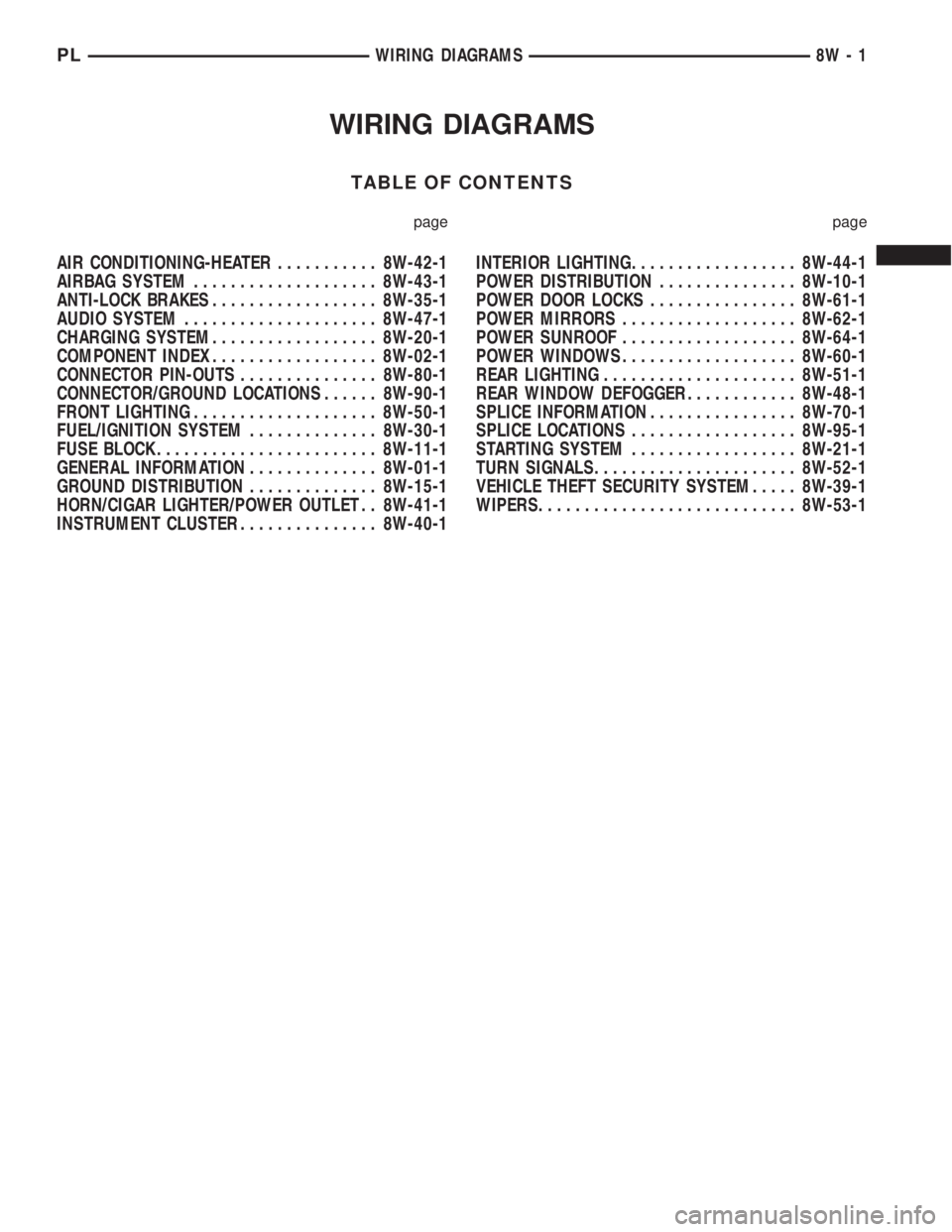
WIRING DIAGRAMS
TABLE OF CONTENTS
page page
AIR CONDITIONING-HEATER........... 8W-42-1
AIRBAG SYSTEM.................... 8W-43-1
ANTI-LOCK BRAKES.................. 8W-35-1
AUDIO SYSTEM..................... 8W-47-1
CHARGING SYSTEM.................. 8W-20-1
COMPONENT INDEX.................. 8W-02-1
CONNECTOR PIN-OUTS............... 8W-80-1
CONNECTOR/GROUND LOCATIONS...... 8W-90-1
FRONT LIGHTING.................... 8W-50-1
FUEL/IGNITION SYSTEM.............. 8W-30-1
FUSE BLOCK........................ 8W-11-1
GENERAL INFORMATION.............. 8W-01-1
GROUND DISTRIBUTION.............. 8W-15-1
HORN/CIGAR LIGHTER/POWER OUTLET . . 8W-41-1
INSTRUMENT CLUSTER............... 8W-40-1INTERIOR LIGHTING.................. 8W-44-1
POWER DISTRIBUTION............... 8W-10-1
POWER DOOR LOCKS................ 8W-61-1
POWER MIRRORS................... 8W-62-1
POWER SUNROOF................... 8W-64-1
POWER WINDOWS................... 8W-60-1
REAR LIGHTING..................... 8W-51-1
REAR WINDOW DEFOGGER............ 8W-48-1
SPLICE INFORMATION................ 8W-70-1
SPLICE LOCATIONS.................. 8W-95-1
STARTING SYSTEM.................. 8W-21-1
TURN SIGNALS...................... 8W-52-1
VEHICLE THEFT SECURITY SYSTEM..... 8W-39-1
WIPERS............................ 8W-53-1
PLWIRING DIAGRAMS 8W - 1
Page 394 of 1285
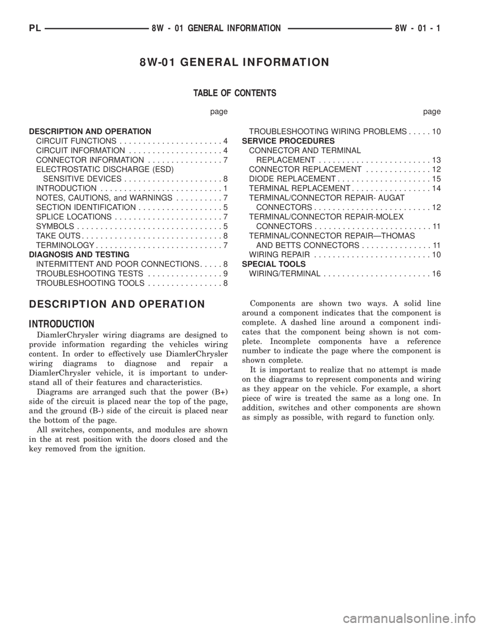
8W-01 GENERAL INFORMATION
TABLE OF CONTENTS
page page
DESCRIPTION AND OPERATION
CIRCUIT FUNCTIONS......................4
CIRCUIT INFORMATION....................4
CONNECTOR INFORMATION................7
ELECTROSTATIC DISCHARGE (ESD)
SENSITIVE DEVICES.....................8
INTRODUCTION..........................1
NOTES, CAUTIONS, and WARNINGS..........7
SECTION IDENTIFICATION..................5
SPLICE LOCATIONS.......................7
SYMBOLS...............................5
TAKE OUTS..............................8
TERMINOLOGY...........................7
DIAGNOSIS AND TESTING
INTERMITTENT AND POOR CONNECTIONS.....8
TROUBLESHOOTING TESTS................9
TROUBLESHOOTING TOOLS................8TROUBLESHOOTING WIRING PROBLEMS.....10
SERVICE PROCEDURES
CONNECTOR AND TERMINAL
REPLACEMENT........................13
CONNECTOR REPLACEMENT..............12
DIODE REPLACEMENT....................15
TERMINAL REPLACEMENT.................14
TERMINAL/CONNECTOR REPAIR- AUGAT
CONNECTORS.........................12
TERMINAL/CONNECTOR REPAIR-MOLEX
CONNECTORS.........................11
TERMINAL/CONNECTOR REPAIRÐTHOMAS
AND BETTS CONNECTORS...............11
WIRING REPAIR.........................10
SPECIAL TOOLS
WIRING/TERMINAL.......................16
DESCRIPTION AND OPERATION
INTRODUCTION
DiamlerChrysler wiring diagrams are designed to
provide information regarding the vehicles wiring
content. In order to effectively use DiamlerChrysler
wiring diagrams to diagnose and repair a
DiamlerChrysler vehicle, it is important to under-
stand all of their features and characteristics.
Diagrams are arranged such that the power (B+)
side of the circuit is placed near the top of the page,
and the ground (B-) side of the circuit is placed near
the bottom of the page.
All switches, components, and modules are shown
in the at rest position with the doors closed and the
key removed from the ignition.Components are shown two ways. A solid line
around a component indicates that the component is
complete. A dashed line around a component indi-
cates that the component being shown is not com-
plete. Incomplete components have a reference
number to indicate the page where the component is
shown complete.
It is important to realize that no attempt is made
on the diagrams to represent components and wiring
as they appear on the vehicle. For example, a short
piece of wire is treated the same as a long one. In
addition, switches and other components are shown
as simply as possible, with regard to function only.
PL8W - 01 GENERAL INFORMATION 8W - 01 - 1
Page 397 of 1285
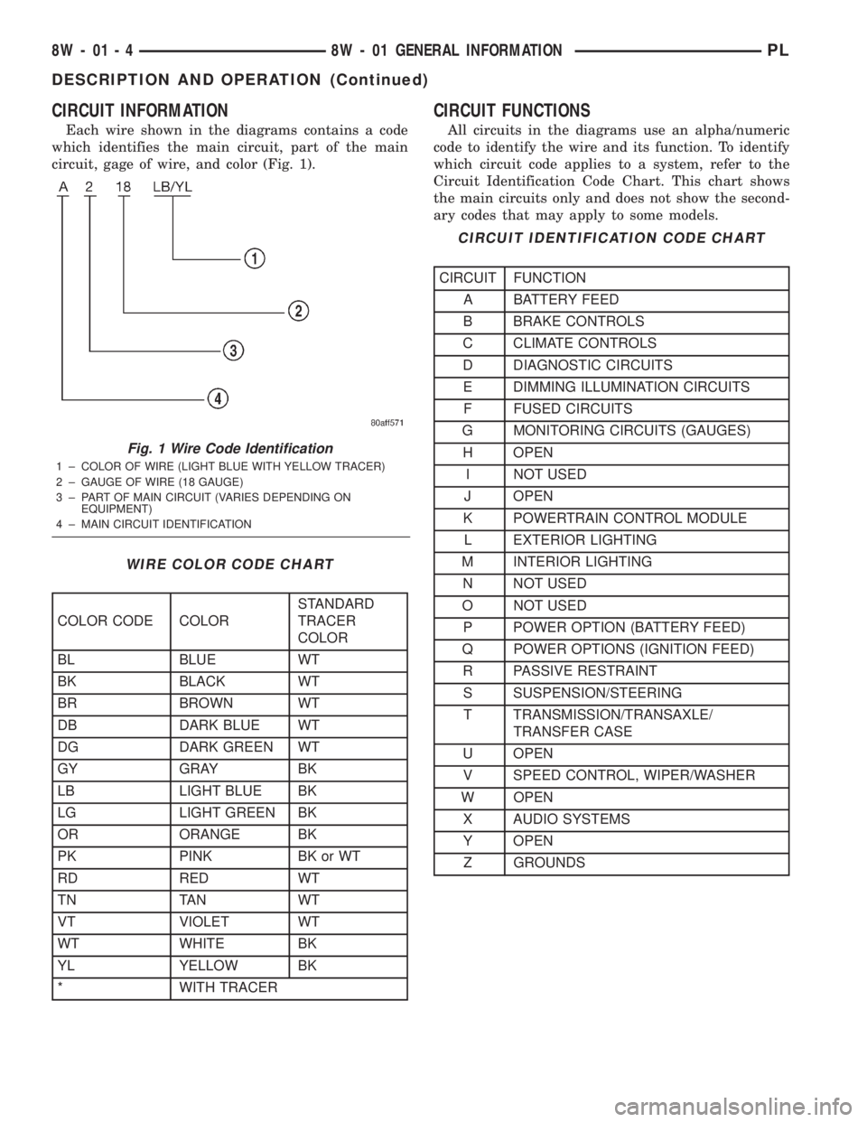
CIRCUIT INFORMATION
Each wire shown in the diagrams contains a code
which identifies the main circuit, part of the main
circuit, gage of wire, and color (Fig. 1).
CIRCUIT FUNCTIONS
All circuits in the diagrams use an alpha/numeric
code to identify the wire and its function. To identify
which circuit code applies to a system, refer to the
Circuit Identification Code Chart. This chart shows
the main circuits only and does not show the second-
ary codes that may apply to some models.
Fig. 1 Wire Code Identification
1 ± COLOR OF WIRE (LIGHT BLUE WITH YELLOW TRACER)
2 ± GAUGE OF WIRE (18 GAUGE)
3 ± PART OF MAIN CIRCUIT (VARIES DEPENDING ON
EQUIPMENT)
4 ± MAIN CIRCUIT IDENTIFICATION
WIRE COLOR CODE CHART
COLOR CODE COLORSTANDARD
TRACER
COLOR
BL BLUE WT
BK BLACK WT
BR BROWN WT
DB DARK BLUE WT
DG DARK GREEN WT
GY GRAY BK
LB LIGHT BLUE BK
LG LIGHT GREEN BK
OR ORANGE BK
PK PINK BK or WT
RD RED WT
TN TAN WT
VT VIOLET WT
WT WHITE BK
YL YELLOW BK
* WITH TRACER
CIRCUIT IDENTIFICATION CODE CHART
CIRCUIT FUNCTION
A BATTERY FEED
B BRAKE CONTROLS
C CLIMATE CONTROLS
D DIAGNOSTIC CIRCUITS
E DIMMING ILLUMINATION CIRCUITS
F FUSED CIRCUITS
G MONITORING CIRCUITS (GAUGES)
H OPEN
I NOT USED
J OPEN
K POWERTRAIN CONTROL MODULE
L EXTERIOR LIGHTING
M INTERIOR LIGHTING
N NOT USED
O NOT USED
P POWER OPTION (BATTERY FEED)
Q POWER OPTIONS (IGNITION FEED)
R PASSIVE RESTRAINT
S SUSPENSION/STEERING
T TRANSMISSION/TRANSAXLE/
TRANSFER CASE
U OPEN
V SPEED CONTROL, WIPER/WASHER
W OPEN
X AUDIO SYSTEMS
Y OPEN
Z GROUNDS
8W - 01 - 4 8W - 01 GENERAL INFORMATIONPL
DESCRIPTION AND OPERATION (Continued)
Page 400 of 1285
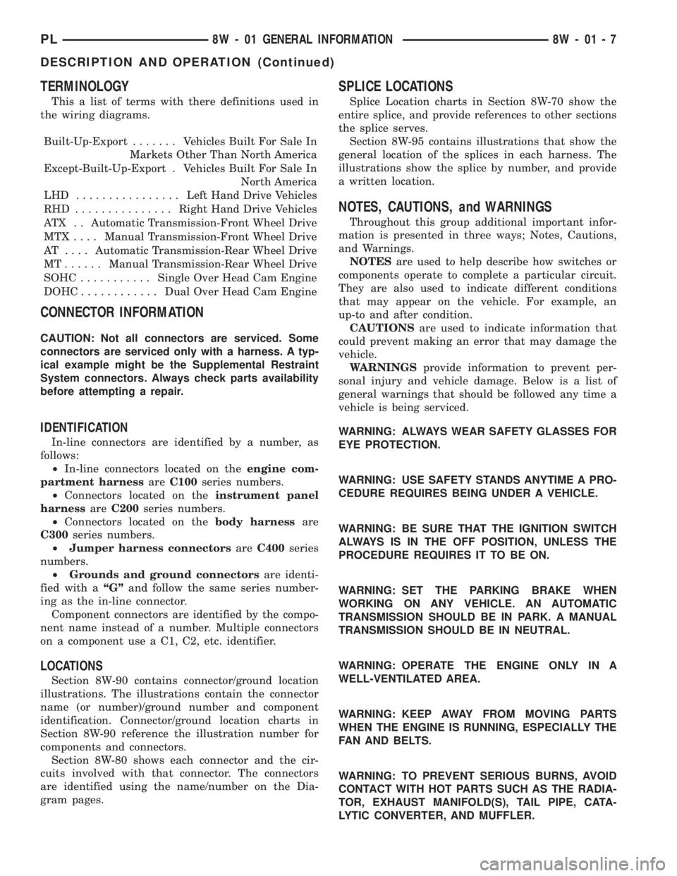
TERMINOLOGY
This a list of terms with there definitions used in
the wiring diagrams.
Built-Up-Export....... Vehicles Built For Sale In
Markets Other Than North America
Except-Built-Up-Export . Vehicles Built For Sale In
North America
LHD ................Left Hand Drive Vehicles
RHD ...............Right Hand Drive Vehicles
ATX . . Automatic Transmission-Front Wheel Drive
MTX ....Manual Transmission-Front Wheel Drive
AT ....Automatic Transmission-Rear Wheel Drive
MT......Manual Transmission-Rear Wheel Drive
SOHC...........Single Over Head Cam Engine
DOHC............Dual Over Head Cam Engine
CONNECTOR INFORMATION
CAUTION: Not all connectors are serviced. Some
connectors are serviced only with a harness. A typ-
ical example might be the Supplemental Restraint
System connectors. Always check parts availability
before attempting a repair.
IDENTIFICATION
In-line connectors are identified by a number, as
follows:
²In-line connectors located on theengine com-
partment harnessareC100series numbers.
²Connectors located on theinstrument panel
harnessareC200series numbers.
²Connectors located on thebody harnessare
C300series numbers.
²Jumper harness connectorsareC400series
numbers.
²Grounds and ground connectorsare identi-
fied with aªGºand follow the same series number-
ing as the in-line connector.
Component connectors are identified by the compo-
nent name instead of a number. Multiple connectors
on a component use a C1, C2, etc. identifier.
LOCATIONS
Section 8W-90 contains connector/ground location
illustrations. The illustrations contain the connector
name (or number)/ground number and component
identification. Connector/ground location charts in
Section 8W-90 reference the illustration number for
components and connectors.
Section 8W-80 shows each connector and the cir-
cuits involved with that connector. The connectors
are identified using the name/number on the Dia-
gram pages.
SPLICE LOCATIONS
Splice Location charts in Section 8W-70 show the
entire splice, and provide references to other sections
the splice serves.
Section 8W-95 contains illustrations that show the
general location of the splices in each harness. The
illustrations show the splice by number, and provide
a written location.
NOTES, CAUTIONS, and WARNINGS
Throughout this group additional important infor-
mation is presented in three ways; Notes, Cautions,
and Warnings.
NOTESare used to help describe how switches or
components operate to complete a particular circuit.
They are also used to indicate different conditions
that may appear on the vehicle. For example, an
up-to and after condition.
CAUTIONSare used to indicate information that
could prevent making an error that may damage the
vehicle.
WARNINGSprovide information to prevent per-
sonal injury and vehicle damage. Below is a list of
general warnings that should be followed any time a
vehicle is being serviced.
WARNING: ALWAYS WEAR SAFETY GLASSES FOR
EYE PROTECTION.
WARNING: USE SAFETY STANDS ANYTIME A PRO-
CEDURE REQUIRES BEING UNDER A VEHICLE.
WARNING: BE SURE THAT THE IGNITION SWITCH
ALWAYS IS IN THE OFF POSITION, UNLESS THE
PROCEDURE REQUIRES IT TO BE ON.
WARNING: SET THE PARKING BRAKE WHEN
WORKING ON ANY VEHICLE. AN AUTOMATIC
TRANSMISSION SHOULD BE IN PARK. A MANUAL
TRANSMISSION SHOULD BE IN NEUTRAL.
WARNING: OPERATE THE ENGINE ONLY IN A
WELL-VENTILATED AREA.
WARNING: KEEP AWAY FROM MOVING PARTS
WHEN THE ENGINE IS RUNNING, ESPECIALLY THE
FAN AND BELTS.
WARNING: TO PREVENT SERIOUS BURNS, AVOID
CONTACT WITH HOT PARTS SUCH AS THE RADIA-
TOR, EXHAUST MANIFOLD(S), TAIL PIPE, CATA-
LYTIC CONVERTER, AND MUFFLER.
PL8W - 01 GENERAL INFORMATION 8W - 01 - 7
DESCRIPTION AND OPERATION (Continued)