2000 DODGE NEON ignition
[x] Cancel search: ignitionPage 263 of 1285
(1) Disconnect the negative battery cable.
(2) Remove the floor console. Refer to Group 23,
Body for the procedure.
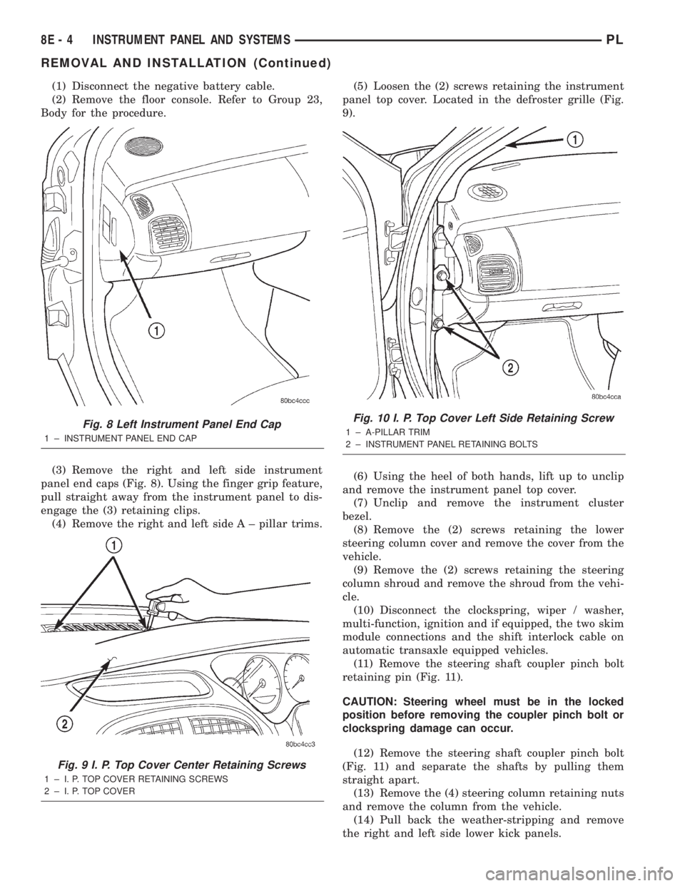
(3) Remove the right and left side instrument
panel end caps (Fig. 8). Using the finger grip feature,
pull straight away from the instrument panel to dis-
engage the (3) retaining clips.
(4) Remove the right and left side A ± pillar trims.(5) Loosen the (2) screws retaining the instrument
panel top cover. Located in the defroster grille (Fig.
9).
(6) Using the heel of both hands, lift up to unclip
and remove the instrument panel top cover.
(7) Unclip and remove the instrument cluster
bezel.
(8) Remove the (2) screws retaining the lower
steering column cover and remove the cover from the
vehicle.
(9) Remove the (2) screws retaining the steering
column shroud and remove the shroud from the vehi-
cle.
(10) Disconnect the clockspring, wiper / washer,
multi-function, ignition and if equipped, the two skim
module connections and the shift interlock cable on
automatic transaxle equipped vehicles.
(11) Remove the steering shaft coupler pinch bolt
retaining pin (Fig. 11).
CAUTION: Steering wheel must be in the locked
position before removing the coupler pinch bolt or
clockspring damage can occur.
(12) Remove the steering shaft coupler pinch bolt
(Fig. 11) and separate the shafts by pulling them
straight apart.
(13) Remove the (4) steering column retaining nuts
and remove the column from the vehicle.
(14) Pull back the weather-stripping and remove
the right and left side lower kick panels.
Fig. 8 Left Instrument Panel End Cap
1 ± INSTRUMENT PANEL END CAP
Fig. 9 I. P. Top Cover Center Retaining Screws
1 ± I. P. TOP COVER RETAINING SCREWS
2 ± I. P. TOP COVER
Fig. 10 I. P. Top Cover Left Side Retaining Screw
1 ± A-PILLAR TRIM
2 ± INSTRUMENT PANEL RETAINING BOLTS
8E - 4 INSTRUMENT PANEL AND SYSTEMSPL
REMOVAL AND INSTALLATION (Continued)
Page 267 of 1285
(17) Install the A/C outlet registers in the center
instrument bezel.
(18) Install the right and left side lower kick pan-
els. Reposition the weather-strip in its original posi-
tion.
(19) Install the steering column. Torque the retain-
ing nuts to 17 N´m (150 in. lbs.).
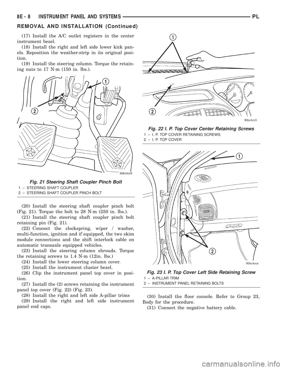
(20) Install the steering shaft coupler pinch bolt
(Fig. 21). Torque the bolt to 28 N´m (250 in. lbs.).
(21) Install the steering shaft coupler pinch bolt
retaining pin (Fig. 21).
(22) Connect the clockspring, wiper / washer,
multi-function, ignition and if equipped, the two skim
module connections and the shift interlock cable on
automatic transaxle equipped vehicles.
(23) Install the steering column shrouds. Torque
the retaining screws to 1.4 N´m (12in. lbs.)
(24) Install the lower steering column cover.
(25) Install the instrument cluster bezel.
(26) Clip the instrument panel top cover in posi-
tion.
(27) Install the (2) screws retaining the instrument
panel top cover (Fig. 22) (Fig. 23).
(28) Install the right and left side A-pillar trims
(29) Install the right and left side instrument
panel end caps.(30) Install the floor console. Refer to Group 23,
Body for the procedure.
(31) Connect the negative battery cable.
Fig. 21 Steering Shaft Coupler Pinch Bolt
1 ± STEERING SHAFT COUPLER
2 ± STEERING SHAFT COUPLER PINCH BOLT
Fig. 22 I. P. Top Cover Center Retaining Screws
1 ± I. P. TOP COVER RETAINING SCREWS
2 ± I. P. TOP COVER
Fig. 23 I. P. Top Cover Left Side Retaining Screw
1 ± A-PILLAR TRIM
2 ± INSTRUMENT PANEL RETAINING BOLTS
8E - 8 INSTRUMENT PANEL AND SYSTEMSPL
REMOVAL AND INSTALLATION (Continued)
Page 270 of 1285
AUDIO SYSTEM
TABLE OF CONTENTS
page page
GENERAL INFORMATION
INTRODUCTION..........................1
DESCRIPTION AND OPERATION
INTERFERENCE ELIMINATION...............1
DIAGNOSIS AND TESTING
AUDIO DIAGNOSTIC TEST PROCEDURES......1
TESTING................................1
BENCH TEST FOR ANTENNA MALFUNCTION...7REMOVAL AND INSTALLATION
CD CHANGER............................7
FRONT DOOR SPEAKER....................8
INSTRUMENT PANEL SPEAKER(S)...........8
MAST and ANTENNA ASSEMBLY.............8
RADIO..................................9
REAR SHELF SPEAKER(S).................10
GENERAL INFORMATION
INTRODUCTION
Operating instructions for the factory installed
audio systems can be found in the Owner's Manual
provided with the vehicle.
The vehicles are equipped with an Interior (Igni-
tion Off Draw) fuse in the Power Distribution Center
located in the engine compartment. After the Interior
(IOD) fuse or battery has been disconnected the clock
will require resetting. The radio station presets have
a nonvolatile memory and will retain the preset sta-
tions after a battery disconnect.
The available radio options are:
²AM/FM Stereo Cassette w/Clock
²AM/FM/CD
²AM/FM Cassette w/CD Changer Controls and
Display
²CD/4 Disc Changer - In-Dash (used w/Radio CD
Changer Controls)
DESCRIPTION AND OPERATION
INTERFERENCE ELIMINATION
The radio utilizes a ground wire plugged on to a
blade terminal and is bolted to the radio chassis.
Both connector and terminal should be securely
attached. The engine has two separate ground straps
to suppress ignition noise which may interfere with
radio reception.
²Left engine mount clip on strap
²Engine to shock tower reinforcement
Inductive type spark plug cables in the high ten-
sion circuit of the ignition system complete the inter-
ference suppression. Faulty or deteriorated spark
plug wires should be replaced.
DIAGNOSIS AND TESTING
AUDIO DIAGNOSTIC TEST PROCEDURES
CAUTION: The CD player will only operate between
approximate temperatures of -23ÉC and +65ÉC (-10ÉF
and +145ÉF).
Whenever a radio malfunction occurs;
(1) First check FUSES:
(a) Power Distribution Center (PDC), Interior
lamp fuse, M1 - Radio Memory Feed
(b) Fuse Block:
(I) Fuse 12, Illumination in the fuse block
(II) Fuse 16, Ignition feed in the fuse block
NOTE: The vehicles are shipped with the INTERIOR
LAMP fuse disconnected.
(2) Verify, the radio wire harness are properly con-
nected before starting normal diagnosis and repair
procedures. Refer to Audio Diagnostic Charts and/or
Group 8W, Wiring Diagrams, Radio Section.
TESTING
The antenna has a short cable which connects into
the instrument panel harness. The connection is
made on the right side of the instrument panel.
Antenna performance may be tested by substitut-
ing a known good antenna. It is also possible to
check short or open circuits with an ohmmeter or
continuity light once the antenna cable is discon-
nected from the radio as follows:
(1) Continuity should be present between the
antenna mast and radio end pin of antenna cable
plug (Fig. 1).
(2) No continuity should be observed or a very
high resistance of several megohms between the
ground shell of the connector and radio end pin.
PLAUDIO SYSTEM 8F - 1
Page 289 of 1285
INSTALLATION
(1) Install retaining clip to cable at servo.
(2) Install 2 nuts at cable to servo and servo
bracket, tighten to 7 N´m (60 ins. lbs.).
(3) Connect electrical connector to servo.
(4) Connect vacuum hose to servo
SPEED CONTROL SWITCH
The speed control switches are mounted in the
steering wheel and wired through the clock spring
device under the airbag module (Fig. 1).
WARNING: IF REMOVAL OF AIRBAG MODULE IS
NECESSARY, REFER TO THE RESTRAINT SYS-
TEMS.
REMOVAL
(1) Turn off ignition.
(2) Remove two screws from side of each switch.
(3) Rock switch away from airbag and steering
wheel.
(4) Disconnect two-way electrical connector.
(5) Repeat for the other switch.
INSTALLATION
(1) Install switches.
(2) Connect two-way electrical connector.
(3) Install two screws to the side of each switch.
(4) Install airbag, refer to the Restraint Systems
SPEED CONTROL SERVO CABLE
REMOVAL
(1) Disconnect the negative battery cable.
(2) Remove the throttle cable cover.
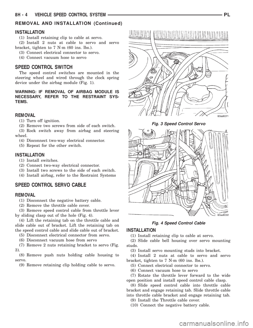
(3) Remove speed control cable from throttle lever
by sliding clasp out of the hole (Fig. 4).
(4) Lift the retaining tab on the throttle cable and
slide cable out of bracket. Lift the retaining tab on
the speed control cable and slide cable out of bracket.
(5) Disconnect electrical connector from servo.
(6) Disconnect vacuum hose from servo
(7) Remove 2 nuts retaining bracket to servo (Fig.
3).
(8) Remove push nuts holding cable housing to
servo.
(9) Remove retaining clip holding cable to servo.
INSTALLATION
(1) Install retaining clip to cable at servo.
(2) Slide cable bell housing over servo mounting
studs.
(3) Install servo mounting studs into bracket.
(4) Install 2 nuts at cable to servo and servo
bracket, tighten to 7 N´m (60 ins. lbs.).
(5) Connect electrical connector to servo.
(6) Connect vacuum hose to servo
(7) Rotate the throttle lever forward to the wide
open position and install speed control cable clasp.
(8) Slide speed control cable into throttle cable
bracket and engage retaining tab. Slide throttle cable
into throttle cable bracket and engage retaining tab.
(9) Install the Throttle cable cover.
(10) Connect the negative battery cable.
Fig. 3 Speed Control Servo
Fig. 4 Speed Control Cable
8H - 4 VEHICLE SPEED CONTROL SYSTEMPL
REMOVAL AND INSTALLATION (Continued)
Page 298 of 1285
WINDSHIELD WIPER and WASHER SYSTEMS
TABLE OF CONTENTS
page page
WINDSHIELD WIPER SYSTEM................ 1WINDSHIELD WASHER SYSTEM.............. 8
WINDSHIELD WIPER SYSTEM
TABLE OF CONTENTS
page page
GENERAL INFORMATION
INTRODUCTION..........................1
DESCRIPTION AND OPERATION
WIPER BLADES...........................1
DIAGNOSIS AND TESTING
WINDSHIELD WIPER CONDITIONS............2
WINDSHIELD WIPER MOTOR................3
WINDSHIELD WIPER/WASHER SWITCH........5
REMOVAL AND INSTALLATION
WINDSHIELD WIPER ARM(S)................5WINDSHIELD WIPER BLADE(S)..............5
WINDSHIELD WIPER BLADE ELEMENT........5
WINDSHIELD WIPER LINKAGE...............5
WINDSHIELD WIPER MODULE...............6
WINDSHIELD WIPER MOTOR................6
WINDSHIELD WIPER/WASHER SWITCH........6
CLEANING AND INSPECTION
WINDSHIELD WIPER BLADE(S)..............6
ADJUSTMENTS
WINDSHIELD WIPER ARM(S)................6
GENERAL INFORMATION
INTRODUCTION
WARNING: ON VEHICLES EQUIPPED WITH AIR-
BAGS, REFER TO GROUP 8M, PASSIVE
RESTRAINT SYSTEMS FOR STEERING WHEEL
REMOVAL AND INSTALLATION.
The windshield wipers will only operate with the
ignition switch in the ACCESSORY or IGNITION
RUN position. The wiper circuit is protected against
over loads by a fuse in the fuse block and a circuit
breaker within the wiper motor. This protects the cir-
cuitry of the wiper system and the vehicle. The wiper
motor has permanent magnet fields.
The intermittent wiper system, in addition to low
and high speed, has a delay mode and a pulse wipe
mode. The delay mode has a range of 1 to 15 seconds.
Pulse wipe is accomplished by momentarily moving
the stalk lever into the WASH position while the
wiper switch is in either OFF or DELAY position.
The wiper blades then sweep once or twice and
return to the previous wiper switch mode, OFF or
DELAY.The intermittent wiper function is integral to the
wiper switch. All electronics and relay are inside the
switch assembly.
The wiper system completes the wipe cycle when
the switch is turned OFF. The blades park in the
lowest portion of the wipe pattern.
The wiper switch also includes the MIST feature
which provides a single wipe when actuated.
DESCRIPTION AND OPERATION
WIPER BLADES
Wiper blades, exposed to the weather for a long
period of time, tend to lose their wiping effectiveness.
Periodic cleaning of the wiper blade is suggested to
remove the accumulation of salt and road film. The
wiper blades, arms, and windshield should be
cleaned with a sponge or cloth and a mild detergent
or nonabrasive cleaner. If the blades continue to
streak or smear, they should be replaced. The right
and left wipers are different blade lengths. The
driver side length is 550 mm and the passenger side
length is 475 mm. The blades should not be inter-
changed.
PLWINDSHIELD WIPER and WASHER SYSTEMS 8K - 1
Page 300 of 1285
(a) If no voltage, repair wiring as necessary. If
OK, go to Step b.
(b) Check wiper switch low speed. Connect volt-
meter positive lead to terminal 6 of the wiper
switch connector. Move wiper stalk to LOW posi-
tion. If no voltage, replace switch.
(c) Check wiper switch high speed, connect volt-
meter positive lead to terminal 5 of the wiper
switch connector. Move wiper stalk to HIGH posi-
tion. If no voltage, replace switch.
(7) Disconnect motor connector and replace fuse 1
in fuse block.
(a) If fuse does not blow, replace motor.
(b) If fuse blows, disconnect wiper switch and
replace fuse.
(c) If fuse does not blow, replace switch.
(d) If fuse blows, repair wiring as necessary.
MOTOR OPERATES SLOWLY AT ALL SPEEDS
(1) Remove wiper arms and cowl screen. Discon-
nect motor linkage from motor. Connect an ammeter
between battery positive terminal and terminal 4 of
the motor connector. Turn wiper motor on and check
ampere reading.
If motor runs and ammeter reading is more than 6
amps, go to Step 2. If less than 6 amps, go to Step 3.
When replacing drive link nut tighten to 11 to 12
N´m (98 to 106 in. lbs.) torque.
(2) Using an ohmmeter, check the high and low
circuits for a short to ground. Refer to Group 8W,
Wiring Diagrams.
(3) Check to see if wiper linkage or pivots are
binding or caught.
WIPERS RUN AT HIGH SPEED WITH SWITCH IN
LOW SPEED POSITION OR WIPERS RUN AT LOW
SPEED WITH SWITCH IN HIGH SPEED POSITION.
(1) Check for crossed wires in the motor pigtail
wire connector. Refer to Group 8W, Wiring Diagrams.
(2) Check for crossed wires in harness connector
from wiper switch to motor.
(3) If OK, replace wiper switch.
WIPERS WILL OPERATE CONTINUOUSLY WITH
THE SWITCH IN THE INTERMITTENT POSITION -
WHEN WIPER SWITCH IS TURNED OFF, WIPERS
STOP WHEREVER THEY ARE WITHOUT
RETURNING TO PARK POSITION.
(1) Check at motor ground strap for a good ground.
(2) Turn ignition switch OFF. Disconnect the wiper
switch harness connector. Using an ohmmeter with
the motor in the park position, check for continuity
between terminal 2 of the wiper switch harness con-
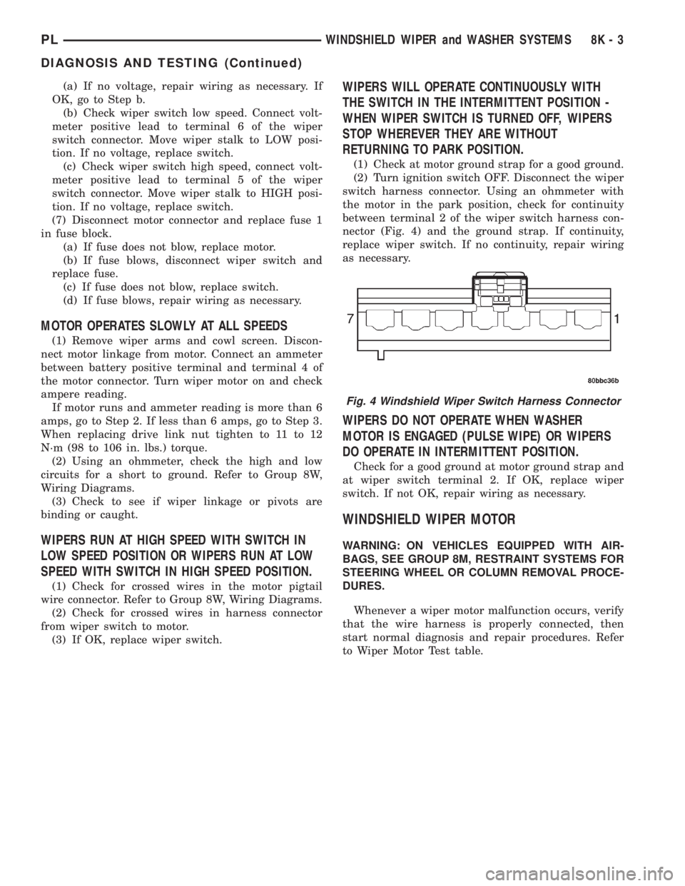
nector (Fig. 4) and the ground strap. If continuity,
replace wiper switch. If no continuity, repair wiring
as necessary.
WIPERS DO NOT OPERATE WHEN WASHER
MOTOR IS ENGAGED (PULSE WIPE) OR WIPERS
DO OPERATE IN INTERMITTENT POSITION.
Check for a good ground at motor ground strap and
at wiper switch terminal 2. If OK, replace wiper
switch. If not OK, repair wiring as necessary.
WINDSHIELD WIPER MOTOR
WARNING: ON VEHICLES EQUIPPED WITH AIR-
BAGS, SEE GROUP 8M, RESTRAINT SYSTEMS FOR
STEERING WHEEL OR COLUMN REMOVAL PROCE-
DURES.
Whenever a wiper motor malfunction occurs, verify
that the wire harness is properly connected, then
start normal diagnosis and repair procedures. Refer
to Wiper Motor Test table.
Fig. 4 Windshield Wiper Switch Harness Connector
PLWINDSHIELD WIPER and WASHER SYSTEMS 8K - 3
DIAGNOSIS AND TESTING (Continued)
Page 302 of 1285
WINDSHIELD WIPER/WASHER SWITCH
To test the switch, first disconnect the switch wires
from the body wiring in the steering column. Using
an ohmmeter test for continuity between the termi-
nals of the wiper switch. Refer to Group 8T Turn Sig-
nal and Hazard Warning Systems, Multi-Function
Switch Diagnosis and Testing.
REMOVAL AND INSTALLATION
WINDSHIELD WIPER ARM(S)
REMOVAL
(1) Place the wiper arm/blades in the PARK posi-
tion and turn ignition OFF.
(2) Using a trim stick (special tool #C-4755), gently
pry up on arm cap and remove.
(3) Remove wiper arm retaining nut.
(4) Remove the arm from the pivot using a rocking
motion while the arm is in an over/centered position.
(5) Clean metal splinters OFF the pivot shafts.
INSTALLATION
For installation reverse above procedures. Before
installation activate wiper system to ensure the
wiper module is in the PARK position. Position wiper
arms so that the heel of the blade(s) is on the park
line on the windshield. Refer to Adjustments in this
section for Wiper Arm Adjustment.
WINDSHIELD WIPER BLADE(S)
REMOVAL
(1) Lift wiper arm to the over center position.
(2) Remove blade assembly from arm by pushing
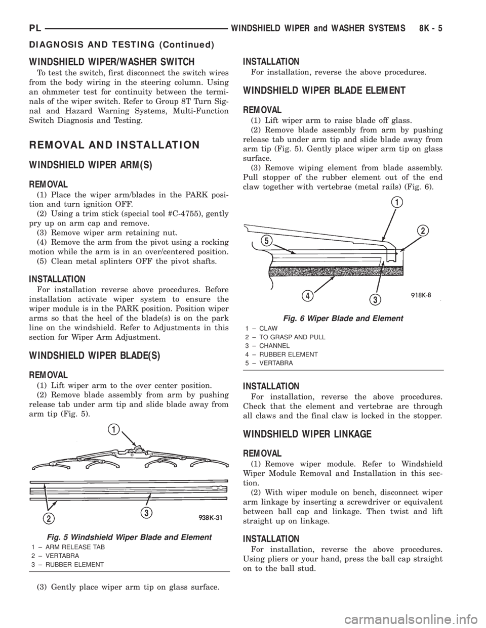
release tab under arm tip and slide blade away from
arm tip (Fig. 5).
(3) Gently place wiper arm tip on glass surface.
INSTALLATION
For installation, reverse the above procedures.
WINDSHIELD WIPER BLADE ELEMENT
REMOVAL
(1) Lift wiper arm to raise blade off glass.
(2) Remove blade assembly from arm by pushing
release tab under arm tip and slide blade away from
arm tip (Fig. 5). Gently place wiper arm tip on glass
surface.
(3) Remove wiping element from blade assembly.
Pull stopper of the rubber element out of the end
claw together with vertebrae (metal rails) (Fig. 6).
INSTALLATION
For installation, reverse the above procedures.
Check that the element and vertebrae are through
all claws and the final claw is locked in the stopper.
WINDSHIELD WIPER LINKAGE
REMOVAL
(1) Remove wiper module. Refer to Windshield
Wiper Module Removal and Installation in this sec-
tion.
(2) With wiper module on bench, disconnect wiper
arm linkage by inserting a screwdriver or equivalent
between ball cap and linkage. Then twist and lift
straight up on linkage.
INSTALLATION
For installation, reverse the above procedures.
Using pliers or your hand, press the ball cap straight
on to the ball stud.
Fig. 5 Windshield Wiper Blade and Element
1 ± ARM RELEASE TAB
2 ± VERTABRA
3 ± RUBBER ELEMENT
Fig. 6 Wiper Blade and Element
1 ± CLAW
2 ± TO GRASP AND PULL
3 ± CHANNEL
4 ± RUBBER ELEMENT
5 ± VERTABRA
PLWINDSHIELD WIPER and WASHER SYSTEMS 8K - 5
DIAGNOSIS AND TESTING (Continued)
Page 308 of 1285
LAMPS
TABLE OF CONTENTS
page page
LAMP DIAGNOSIS......................... 1
HEADLAMP ALIGNMENT.................... 4
LAMP BULB SERVICE...................... 7LAMP SERVICE........................... 12
LAMP SYSTEMS.......................... 16
BULB APPLICATION....................... 17
LAMP DIAGNOSIS
TABLE OF CONTENTS
page page
DESCRIPTION AND OPERATION
DIAGNOSTIC PROCEDURES................1
SAFETY PRECAUTIONS....................1
DAYTIME RUNNING LAMP MODULE...........1DIAGNOSIS AND TESTING
HEADLAMP DIAGNOSIS....................1
FOG LAMP..............................3
DESCRIPTION AND OPERATION
DIAGNOSTIC PROCEDURES
When a vehicle experiences problems with the
headlamp system, verify the condition of the battery
connections, fuses, charging system, headlamp bulbs,
wire connectors, relay, high beam switch, dimmer
switch, and headlamp switch. Refer to Group 8W,
Wiring Diagrams for component locations and circuit
information.
SAFETY PRECAUTIONS
WARNING: EYE PROTECTION SHOULD BE USED
WHEN SERVICING GLASS COMPONENTS. PER-
SONAL INJURY CAN RESULT.
CAUTION: Do not touch the glass of halogen bulbs
with fingers or other possibly oily surface, reduced
bulb life will result.
Do not use bulbs with higher candle power than
indicated in the Bulb Application table at the end of
this group. Damage to lamp and/or Daytime Run-
ning Lamp Module can result.
Do not use fuses, circuit breakers or relays hav-
ing greater amperage value than indicated on the
fuse panel or in the Owners Manual.When it is necessary to remove components to ser-
vice another, it should not be necessary to apply
excessive force or bend a component to remove it.
Before damaging a trim component, verify hidden
fasteners or captured edges are not holding the com-
ponent in place.
DAYTIME RUNNING LAMP MODULE
PL vehicles built for use in Canada are equipped
with a Daytime Running Lamp (DRL) system. Turn
signal lamp circuitry always comes from the multi-
function switch, and goes to the cluster connector,
into the cluster, then back out to the front turn sig-
nal switch lamps. The Canadian cluster provides
steady illumination of the front turn signal when the
ignition switch is in the ON position. The DRL func-
tion may be inhibited by activating the turn signals,
the hazard flashers, the headlamp switch, or park
brake.
DIAGNOSIS AND TESTING
HEADLAMP DIAGNOSIS
Always begin any diagnosis by testing all of the
fuses and circuit breakers in the system. Refer to
Group 8W, Wiring Diagrams.
Conventional and halogen headlamps are inter-
changeable. It is recommended that they not be
intermixed on a given vehicle.
PLLAMPS 8L - 1