Page 2300 of 4592

DI030±05
DI±148
± DIAGNOSTICSAUTOMATIC TRANSAXLE
PROBLEM SYMPTOMS TABLE
If a normal code is displayed during the DTC check but the trouble still occurs, check the circuits for each
symptom in the order given in the charts on the following pages and proceed to the page given for trouble-
shooting.
The Matrix Chart is divided into 3 chapters.
Chapter 1: Electronic Circuit Matrix Chart
Chapter 2: On±vehicle Repair Matrix Chart
Chapter 3: Off±vehicle repair Matrix Chart
�If the instruction ºProceed to next circuit inspection shown on matrix chartº is given in the flow
chart for each circuit, proceed to the circuit with the next highest number in the table to continue
the check.
�If the trouble still occurs even though there are no abnormalities in any of the other circuits, then
check and replace the ECM.
Chapter 1: Electronic Circuit Matrix Chart
SymptomSuspect AreaSee page
No up±shift
(A particular gear, from 1st to 3rd gear, is not up±shifted)3. ECMIN±29
No up±shift (3rd " O/D)
1. O/D main switch & O/D OFF indicator light circuit
2. O/D cancel signal circuit
3. ECMDI±171
DI±169
IN±29
No down±shift (O/D " 3rd)1. ECMIN±29
No down±shift
(A particular gear, from 3rd to 1st gear, is not down±shifted)1. ECMIN±29
No lock±up or No lock±up off1. Stop light switch circuit
2. ECMDI±164
IN±29
Shift point too high or too low1. ECMIN±29
Up±shift to O/D from 3rd while O/D main switch is OFF1. O/D main switch & O/D OFF indicator light circuit
2. ECMDI±171
IN±29
Up±shift to O/D from 3rd while engine is cold1. ECMIN±29
Poor acceleration1. ECMIN±29
No kick±down1. ECMIN±29
Engine stalls when starting off or stopping1. ECMIN±29
Page 2302 of 4592

DI±150
± DIAGNOSTICSAUTOMATIC TRANSAXLE
Chapter 3: Off±Vehicle Repair
(�: A140E AUTOMATIC TRANSAXLE Repair Manual Pub. No. RM385U)
(*: 1999 CAMRY Repair Manual Pub. No. RM654U AUTOMATIC TRANSAXLE (A140E) Section)
SymptomSuspect AreaSee page
Vehicle does not move in any forward positions and reverse posi-
tion
1. Front and rear planetary gear
2. O/D planetary gear
3. O/D one±way clutch (F
0)
4. O/D direct clutch (C
0)
5. O/D brake (B
0)
6. Forward clutch (C
1)
�
�
�
�
�
�
Vehicle does not move in R position
1. Front and rear planetary gear unit
2. Direct clutch (C
2)
3. O/D direct clutch (C
0)
4. 1st & reverse brake (B
3)
�
�
�
�
No up±shift (1st " 2nd)1. No. 1 one±way clutch (F1)
2. 2nd brake (B
2)
�
�
No up±shift (2nd " 3rd)1. Direct clutch (C2)�
No up±shift (3rd " O/D)1. O/D brake (B0)�
No lock±up or No lock±up off1. Torque converter clutch*AX±26
Harsh engagement (N " D)
1. Forward clutch (C1)
2. O/D one±way clutch (F
0)
3. No. 2 one±way clutch (F
2)
�
�
�
Harsh engagement (N " R)1. Direct clutch (C2)
2. 1st & reverse brake (B
3)
�
�
Harsh engagement (Lock±up)1. Torque converter clutch*AX±26
Slip or shudder (Forward position: After warm±up)
1. Torque converter clutch
2. O/D direct clutch (C
0)
3. Forward clutch (C
1)
4. O/D one±way clutch (F
0)
*AX±26
�
�
�
Slip or shudder (R position)
1. Direct clutch (C2)
2. 1st & reverse brake (B
3)
3. O/D direct clutch (C
0)
�
�
�
Slip or shudder (1st)1. No. 2 one±way clutch (F2)�
Slip or shudder (2nd)1. No. 1 one±way clutch (F1)
2. 2nd brake (B
2)
�
�
Slip or shudder (3rd)1. Direct clutch (C2)�
Slip or shudder (O/D)1. O/D brake (B0)�
No engine braking (1st ~ 3rd: D position)1. 2nd brake (B2)�
No engine braking (1st: L position)1. 1st & reverse brake (B3)�
No engine braking (2nd: 2 position)1. 2nd coast brake (B1)�
Poor acceleration (All positions)1. Torque converter clutch
2. O/D planetary gear*AX±26
�
Poor acceleration (O/D)1. O/D direct clutch (C0)
2. O/D planetary gear�
�
Large shift shock or engine stalls when starting off or stopping1. Torque converter clutch*AX±26
Page 2331 of 4592

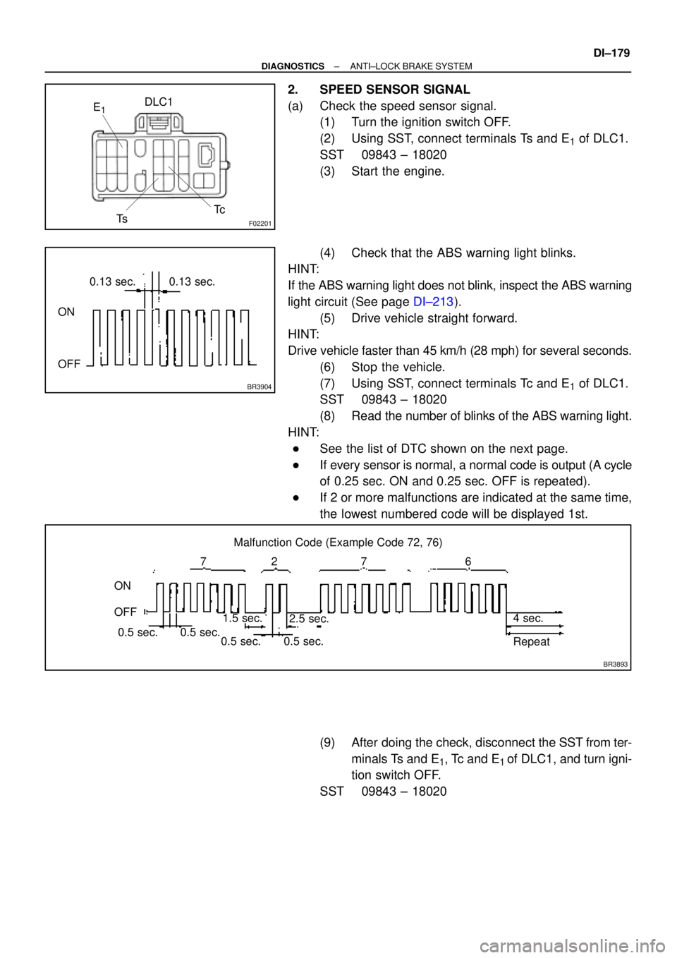
F02201
DLC1
TsTc E1
BR3904
0.13 sec. 0.13 sec.
ON
OFF
BR3893
Malfunction Code (Example Code 72, 76)
72 67
ON
OFF
0.5 sec. 0.5 sec. 0.5 sec. 0.5 sec.1.5 sec.
2.5 sec.4 sec.
Repeat
± DIAGNOSTICSANTI±LOCK BRAKE SYSTEM
DI±179
2. SPEED SENSOR SIGNAL
(a) Check the speed sensor signal.
(1) Turn the ignition switch OFF.
(2) Using SST, connect terminals Ts and E
1 of DLC1.
SST 09843 ± 18020
(3) Start the engine.
(4) Check that the ABS warning light blinks.
HINT:
If the ABS warning light does not blink, inspect the ABS warning
light circuit (See page DI±213).
(5) Drive vehicle straight forward.
HINT:
Drive vehicle faster than 45 km/h (28 mph) for several seconds.
(6) Stop the vehicle.
(7) Using SST, connect terminals Tc and E
1 of DLC1.
SST 09843 ± 18020
(8) Read the number of blinks of the ABS warning light.
HINT:
�See the list of DTC shown on the next page.
�If every sensor is normal, a normal code is output (A cycle
of 0.25 sec. ON and 0.25 sec. OFF is repeated).
�If 2 or more malfunctions are indicated at the same time,
the lowest numbered code will be displayed 1st.
(9) After doing the check, disconnect the SST from ter-
minals Ts and E
1, Tc and E1 of DLC1, and turn igni-
tion switch OFF.
SST 09843 ± 18020
Page 2475 of 4592

N17520
(1)
(2)
(1)
No.Operation MethodCRUISE MAIN Indicator Light
Blinking PatternDiagnosis
1 Turn SET/COAST switch ON
2Turn RES/ACC switch ON
3Turn CANCEL switch ON
Turn stop light switch ON
Depress brake pedal
Turn PNP switch OFF
(Shift to except D position)
4Drive at about 40 km/h
(25 mph)or higher
Drive at about 40 km/h
(25 mph) or below
LightON
OFF
LightON
OFF
LightON
OFFSwitch ON
Switch OFF
LightON
OFFSwitch OFF
Switch ONSET/COAST switch circuit
is normal
RES/ACC switch circuit
is normal
CANCEL switch circuit
is normal
Stop light switch circuit
is normal
PNP switch circuit is
normal
Vehicle Speed Sensor is
normal
LightON
OFF LightON
OFF
1sec.
0.25 sec.0.25 sec.
± DIAGNOSTICSCRUISE CONTROL SYSTEM
DI±323
5. INPUT SIGNAL CHECK
HINT:
(1): For check No.1 ± No.3
�Turn ignition switch ON.
(2): For check No.4
�Jack up the vehicle.
�Start the engine.
�Shift to D position.
(a) Pull the control switch to SET/COAST or RES/ACC posi-
tion and hold it down or up (1).
(b) Push the main switch ON (2).
(c) Check that the CRUISE MAIN indicator light blinks twice
or 3 times repeatedly after 3 seconds.
(d) Turn the SET/COAST or RES/ACC switch OFF.
(e) Operate each switch as listed in the table below.
(f) Read the blinking pattern of the CRUISE MAIN indicator
light.
(g) After performing the check, turn the main switch OFF.
HINT:
When 2 or more signals are input to the ECU, the lowest num-
bered code will be displayed first.
Page 2479 of 4592
± DIAGNOSTICSCRUISE CONTROL SYSTEM
DI±327
Symbols (Terminals No.)Wiring ColorConditionSTD Voltage (V)
CMS e GND WLWB
Ignition switch ON
Main switch OFF10 ± 16 VCMS e GND
(C16±11 e C16±16)W±L e W±BIgnition switch ON
Main switch ONBelow 0.5 V
SPD e GND
(C16 12C16 16)V±W e W±B
Engine start
Car stoppage.Below 1.5 V or
4.7 ± 16 V
(C16±12 e C16±16)VW e WB
During driving (Pulse generated).3 ± 7 V
IDL e GND LRWB
Ignition switch ON
Throttle valve fully opened.10 ± 16 VIDL e GND
(C16±13 e C16±16)L±R e W±BIgnition switch ON
Throttle valve fully closed.Below 1.5 V
OD e GNDYBWB
During cruise control driving
OD switch ON.10 ± 16 VOD e GND
(C16±14 e C16±16)Y±B e W±BDuring cruise control driving
OD switch OFF (3rd driving)Below 1 V
MO e GND RGWB
During cruise control driving
ACC switch hold ON9 ± 15 VMO e GND
(C16±15 e C16±16)R±G e W±BDuring cruise control driving
COAST switch hold ONBelow 1 V
GND e Body Ground
(C16±16 e Body Ground)W±B e Body
GroundConstantBelow 1 V
Page 2522 of 4592

EC03E±05
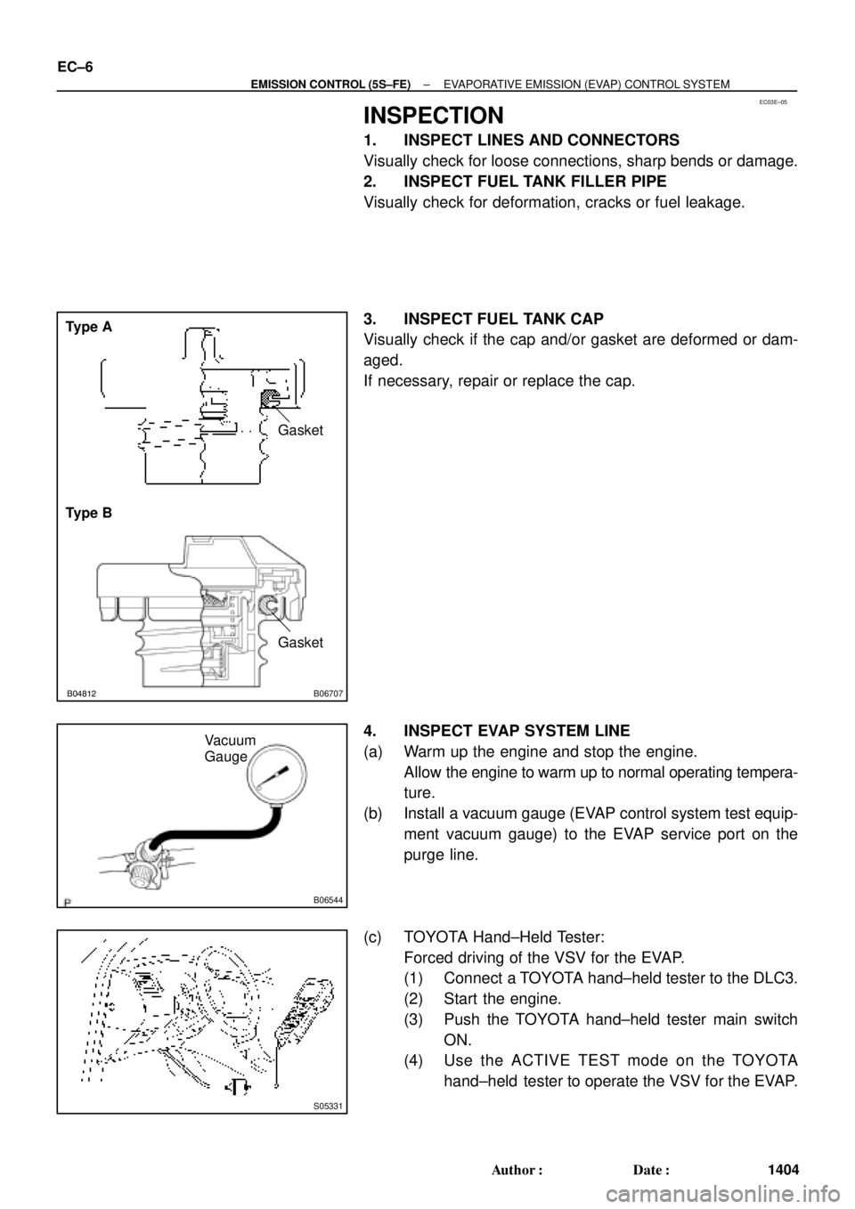
B01082B04812B06707
Type A
Type BGasket
Gasket
B06544
Vacuum
Gauge
S05331
EC±6
± EMISSION CONTROL (5S±FE)EVAPORATIVE EMISSION (EVAP) CONTROL SYSTEM
1404 Author�: Date�:
INSPECTION
1. INSPECT LINES AND CONNECTORS
Visually check for loose connections, sharp bends or damage.
2. INSPECT FUEL TANK FILLER PIPE
Visually check for deformation, cracks or fuel leakage.
3. INSPECT FUEL TANK CAP
Visually check if the cap and/or gasket are deformed or dam-
aged.
If necessary, repair or replace the cap.
4. INSPECT EVAP SYSTEM LINE
(a) Warm up the engine and stop the engine.
Allow the engine to warm up to normal operating tempera-
ture.
(b) Install a vacuum gauge (EVAP control system test equip-
ment vacuum gauge) to the EVAP service port on the
purge line.
(c) TOYOTA Hand±Held Tester:
Forced driving of the VSV for the EVAP.
(1) Connect a TOYOTA hand±held tester to the DLC3.
(2) Start the engine.
(3) Push the TOYOTA hand±held tester main switch
ON.
(4) Use the ACTIVE TEST mode on the TOYOTA
hand±held tester to operate the VSV for the EVAP.
Page 2523 of 4592

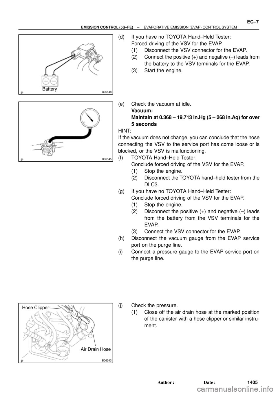
B06548Battery
B06545
B06543
Hose Clipper
Air Drain Hose
± EMISSION CONTROL (5S±FE)EVAPORATIVE EMISSION (EVAP) CONTROL SYSTEM
EC±7
1405 Author�: Date�:
(d) If you have no TOYOTA Hand±Held Tester:
Forced driving of the VSV for the EVAP.
(1) Disconnect the VSV connector for the EVAP.
(2) Connect the positive (+) and negative (±) leads from
the battery to the VSV terminals for the EVAP.
(3) Start the engine.
(e) Check the vacuum at idle.
Vacuum:
Maintain at 0.368 ± 19.713 in.Hg (5 ± 268 in.Aq) for over
5 seconds
HINT:
If the vacuum does not change, you can conclude that the hose
connecting the VSV to the service port has come loose or is
blocked, or the VSV is malfunctioning.
(f) TOYOTA Hand±Held Tester:
Conclude forced driving of the VSV for the EVAP.
(1) Stop the engine.
(2) Disconnect the TOYOTA hand±held tester from the
DLC3.
(g) If you have no TOYOTA Hand±Held Tester:
Conclude forced driving of the VSV for the EVAP.
(1) Stop the engine.
(2) Disconnect the positive (+) and negative (±) leads
from the battery from the VSV terminals for the
EVAP.
(3) Connect the VSV connector for the EVAP.
(h) Disconnect the vacuum gauge from the EVAP service
port on the purge line.
(i) Connect a pressure gauge to the EVAP service port on
the purge line.
(j) Check the pressure.
(1) Close off the air drain hose at the marked position
of the canister with a hose clipper or similar instru-
ment.
Page 2529 of 4592

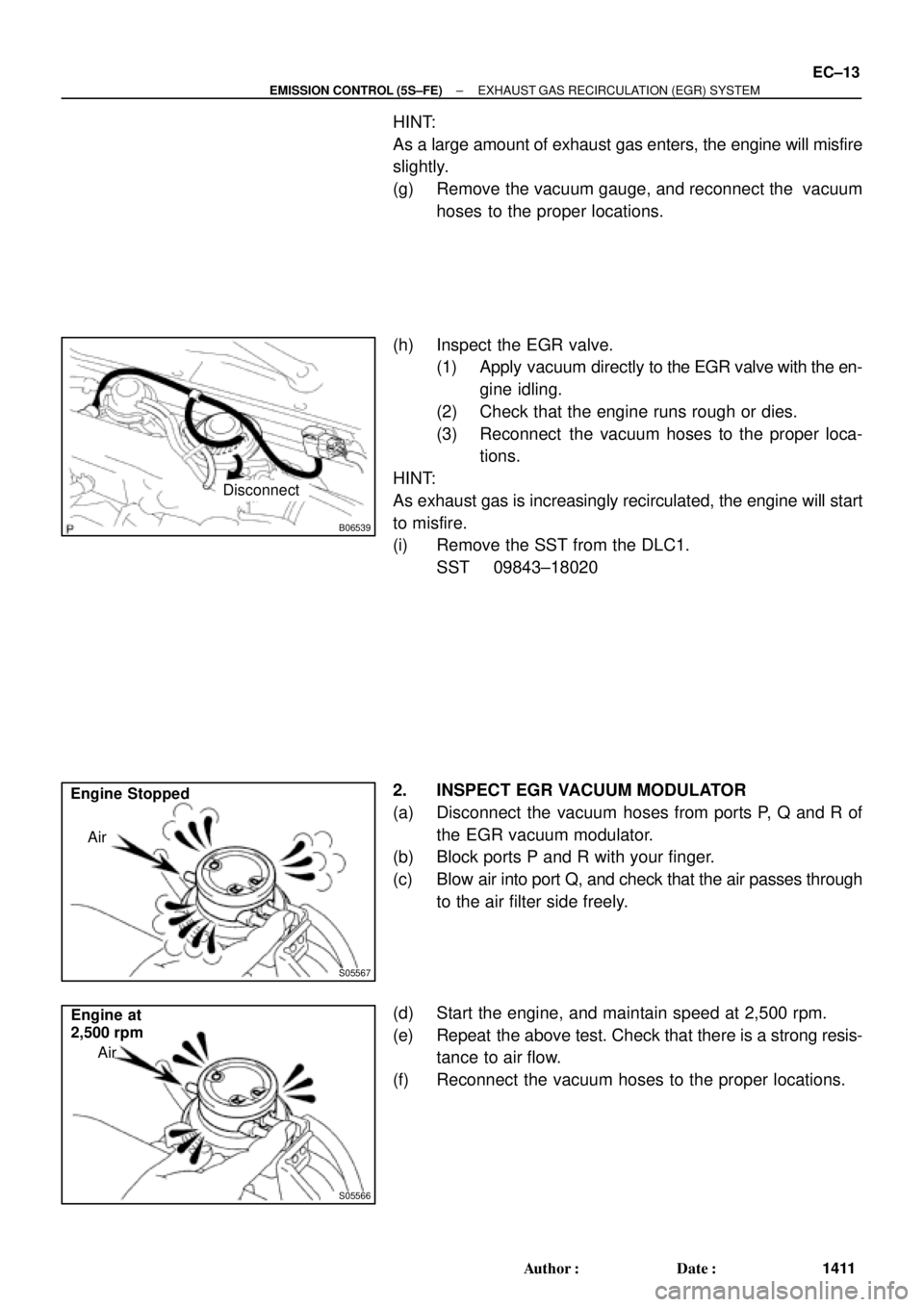
B06539
Disconnect
S05567
Air Engine Stopped
S05566
Engine at
2,500 rpm
Air
± EMISSION CONTROL (5S±FE)EXHAUST GAS RECIRCULATION (EGR) SYSTEM
EC±13
1411 Author�: Date�:
HINT:
As a large amount of exhaust gas enters, the engine will misfire
slightly.
(g) Remove the vacuum gauge, and reconnect the vacuum
hoses to the proper locations.
(h) Inspect the EGR valve.
(1) Apply vacuum directly to the EGR valve with the en-
gine idling.
(2) Check that the engine runs rough or dies.
(3) Reconnect the vacuum hoses to the proper loca-
tions.
HINT:
As exhaust gas is increasingly recirculated, the engine will start
to misfire.
(i) Remove the SST from the DLC1.
SST 09843±18020
2. INSPECT EGR VACUUM MODULATOR
(a) Disconnect the vacuum hoses from ports P, Q and R of
the EGR vacuum modulator.
(b) Block ports P and R with your finger.
(c) Blow air into port Q, and check that the air passes through
to the air filter side freely.
(d) Start the engine, and maintain speed at 2,500 rpm.
(e) Repeat the above test. Check that there is a strong resis-
tance to air flow.
(f) Reconnect the vacuum hoses to the proper locations.