Page 3479 of 4592
B01165
P10595
SST
P10596
SSTUpward
Downward
P10593
SST
P10594
± STARTING (5S±FE)STARTER
ST±13
1720 Author�: Date�:
(8) Remove the starter housing and clutch assembly
from the brass bar.
(9) Using a plastic±faced hammer, tap the clutch shaft
and install the stop collar onto the snap ring.
2. REPLACE FRONT BEARING
(a) Using SST, remove the bearing.
SST 09286±46011
(b) Using SST and a press, press in a new bearing.
NOTICE:
Be careful of the bearing installation direction.
SST 09820±00030
3. REPLACE REAR BEARING
(a) Using SST, remove the bearing.
SST 09286±46011
(b) Using a press, press in a new bearing.
Page 3489 of 4592
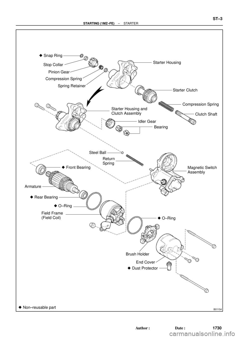
B01154
� Snap Ring
Starter Housing
Starter Clutch
Compression Spring
Clutch Shaft
Starter Housing and
Clutch Assembly
Idler Gear
Bearing Stop Collar
Pinion Gear
Compression Spring
Spring Retainer
Steel Ball
Return
Spring
� Front Bearing
Armature
� O±Ring
Field Frame
(Field Coil)
End Cover Brush Holder � Rear Bearing
� Dust Protector
� Non±reusable part
Magnetic Switch
Assembly
� O±Ring
± STARTING (1MZ±FE)STARTER
ST±3
1730 Author�: Date�:
Page 3497 of 4592
ST01Y±03
B01224
B01225
B01226
B01227
Stop Collar
Pinion Gear
Compression
Spring
B01228
± STARTING (1MZ±FE)STARTER
ST±11
1738 Author�: Date�:
REPLACEMENT
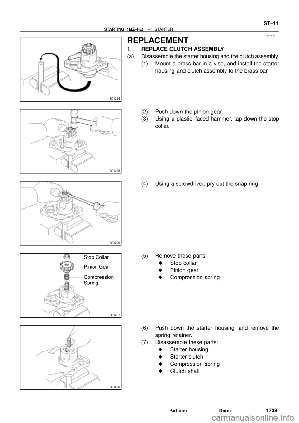
1. REPLACE CLUTCH ASSEMBLY
(a) Disassemble the starter housing and the clutch assembly.
(1) Mount a brass bar in a vise, and install the starter
housing and clutch assembly to the brass bar.
(2) Push down the pinion gear.
(3) Using a plastic±faced hammer, tap down the stop
collar.
(4) Using a screwdriver, pry out the snap ring.
(5) Remove these parts:
�Stop collar
�Pinion gear
�Compression spring
(6) Push down the starter housing, and remove the
spring retainer.
(7) Disassemble these parts:
�Starter housing
�Starter clutch
�Compression spring
�Clutch shaft
Page 3498 of 4592
B01229
Starter Housing
Starter
ClutchCompression
Spring
Clutch
Shaft
B01230
B01231B01670
Spring
Retainer Pinion
GearStop
Collar
Compression
Spring
B01232
B01233
ST±12
± STARTING (1MZ±FE)STARTER
1739 Author�: Date�:
(b) Assemble the starter housing and the clutch assembly
(1) Assemble these parts:
�Starter housing
�Starter clutch
�Compression spring
�Clutch shaft
(2) Mount a brass bar in a vise, install the starter hous-
ing and clutch assembly to the brass bar.
(3) Push down the starter housing, and install these
parts:
�Spring retainer
�Compression spring
�Pinion gear
�Stop collar
(4) Push down the pinion gear.
(5) Using snap ring pliers, install a new snap ring.
(6) Using pliers, compress the snap ring.
(7) Check that the snap ring fits correctly.
Page 3499 of 4592
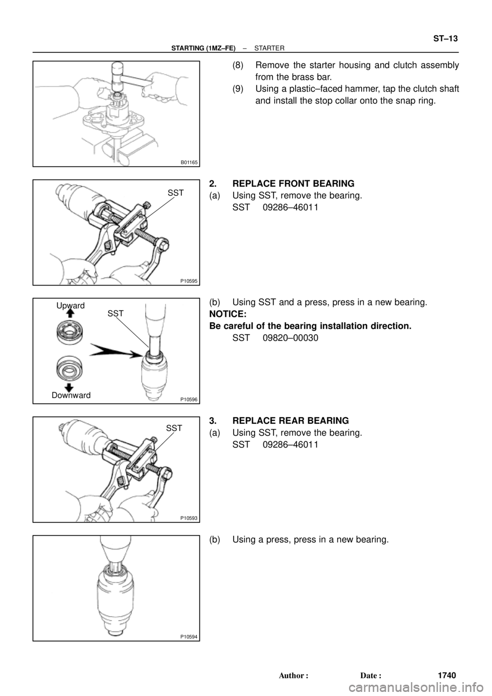
B01165
P10595
SST
P10596
SSTUpward
Downward
P10593
SST
P10594
± STARTING (1MZ±FE)STARTER
ST±13
1740 Author�: Date�:
(8) Remove the starter housing and clutch assembly
from the brass bar.
(9) Using a plastic±faced hammer, tap the clutch shaft
and install the stop collar onto the snap ring.
2. REPLACE FRONT BEARING
(a) Using SST, remove the bearing.
SST 09286±46011
(b) Using SST and a press, press in a new bearing.
NOTICE:
Be careful of the bearing installation direction.
SST 09820±00030
3. REPLACE REAR BEARING
(a) Using SST, remove the bearing.
SST 09286±46011
(b) Using a press, press in a new bearing.
Page 3510 of 4592
SR06E±01
R09599
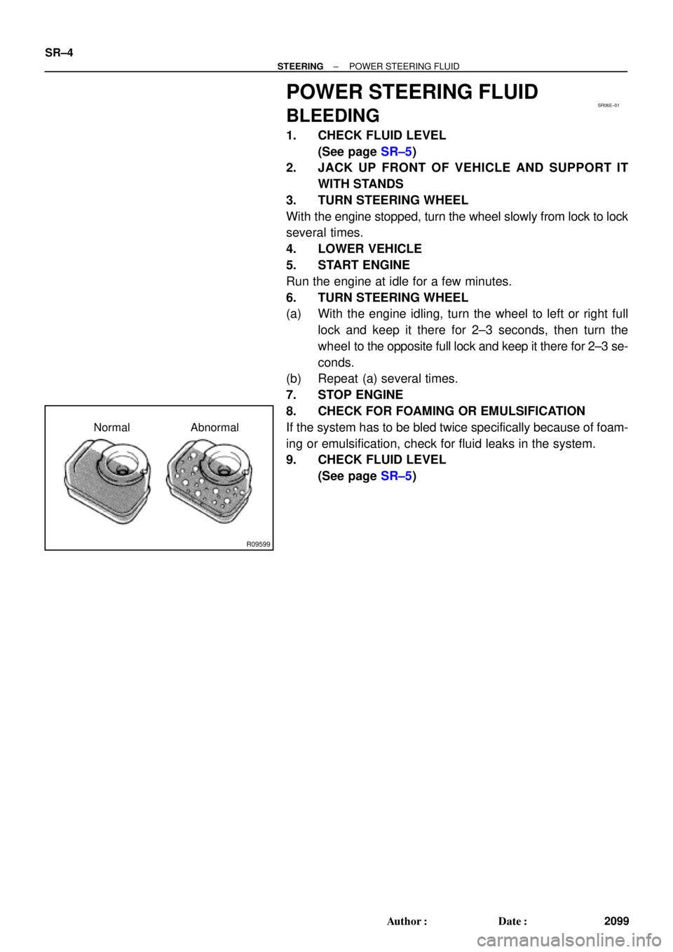
Normal Abnormal SR±4
± STEERINGPOWER STEERING FLUID
2099 Author�: Date�:
POWER STEERING FLUID
BLEEDING
1. CHECK FLUID LEVEL
(See page SR±5)
2. JACK UP FRONT OF VEHICLE AND SUPPORT IT
WITH STANDS
3. TURN STEERING WHEEL
With the engine stopped, turn the wheel slowly from lock to lock
several times.
4. LOWER VEHICLE
5. START ENGINE
Run the engine at idle for a few minutes.
6. TURN STEERING WHEEL
(a) With the engine idling, turn the wheel to left or right full
lock and keep it there for 2±3 seconds, then turn the
wheel to the opposite full lock and keep it there for 2±3 se-
conds.
(b) Repeat (a) several times.
7. STOP ENGINE
8. CHECK FOR FOAMING OR EMULSIFICATION
If the system has to be bled twice specifically because of foam-
ing or emulsification, check for fluid leaks in the system.
9. CHECK FLUID LEVEL
(See page SR±5)
Page 3511 of 4592

or less
Engine Idling Engine Stopped
± STEERINGPOWER STEERING FLUID
SR±5
2100 Author�: Date�:
INSPECTION
1. CHECK FLUID LEVEL
(a) Keep t")
SR06F±01
R00427
R09599
Normal Abnormal
R11562
5 mm (0.2 in.)
or less
Engine Idling Engine Stopped
± STEERINGPOWER STEERING FLUID
SR±5
2100 Author�: Date�:
INSPECTION
1. CHECK FLUID LEVEL
(a) Keep the vehicle level.
(b) With the engine stopped, check the fluid level in the oil
reservoir.
If necessary, add fluid.
Fluid: ATF DEXRON® II or III
HINT:
Check that the fluid level is within the HOT LEVEL range on the
reservoir. If the fluid is cold, check that it is within the COLD
LEVEL range.
(c) Start the engine and run it at idle.
(d) Turn the steering wheel from lock to lock several times to
boost fluid temperature.
Fluid temperature: 80°C (176°F)
(e) Check for foaming or emulsification.
If there is foaming or emulsification, bleed power steering
system.
(See page SR±4)
(f) With the engine idling, measure the fluid level in the oil
reservoir.
(g) Stop the engine.
(h) Wait a few minutes and remeasure the fluid level in the oil
reservoir.
Maximum fluid level rise: 5 mm (0.20 in.)
If a problem is found, bleed power steering system.
(See page SR±4)
(i) Check the fluid level.
Page 3514 of 4592
R07653
SR06G±01
F01477
SR±8
± STEERINGSTEERING WHEEL
2103 Author�: Date�:
STEERING WHEEL
INSPECTION
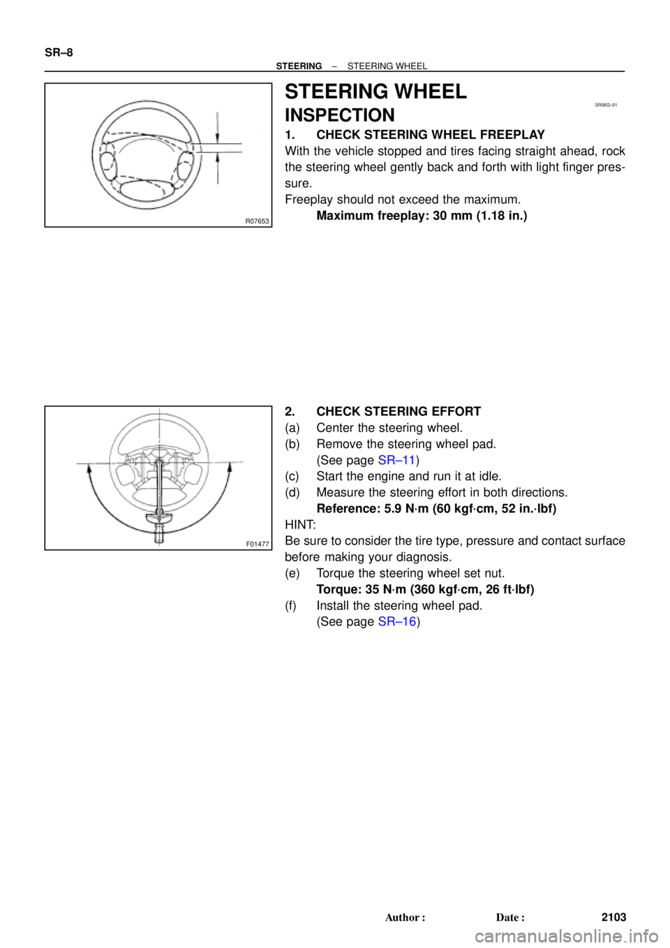
1. CHECK STEERING WHEEL FREEPLAY
With the vehicle stopped and tires facing straight ahead, rock
the steering wheel gently back and forth with light finger pres-
sure.
Freeplay should not exceed the maximum.
Maximum freeplay: 30 mm (1.18 in.)
2. CHECK STEERING EFFORT
(a) Center the steering wheel.
(b) Remove the steering wheel pad.
(See page SR±11)
(c) Start the engine and run it at idle.
(d) Measure the steering effort in both directions.
Reference: 5.9 N´m (60 kgf´cm, 52 in.´lbf)
HINT:
Be sure to consider the tire type, pressure and contact surface
before making your diagnosis.
(e) Torque the steering wheel set nut.
Torque: 35 N´m (360 kgf´cm, 26 ft´lbf)
(f) Install the steering wheel pad.
(See page SR±16)

STARTER
173")