1999 TOYOTA CAMRY stop start
[x] Cancel search: stop startPage 4052 of 4592
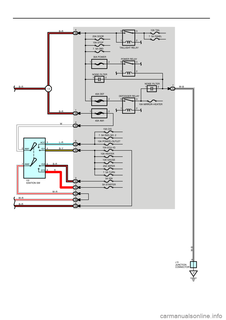
1230A POWER
1240A DEF
12
40A AM1 1B4
1B1
1K2
1K6
1K1
1K3
1K4
1K5
1B51J7
AM1
AM2 7 23
6 ACC
IG1
IG2
ST24
8I 2
IF 25A DOOR
15A STOP
7. 5A OBDTAI LL IGHT REL AY10A TAIL
7. 5A PANEL
POWER RELAY
NOISE FILTER
NOISE FILTER
DEFOGGER RELAY
10A MIRROR±HEATER
15A CIG
7. 5A RAD±NO. 2
15A POWER±OUTLET
15A ECU±IG
10A HEATER
10A GAUGE
25A WIPER
7. 5A TURN
5A IGN
5A STARTER
JUNCTION
CONNECTOR IGNITION SW I10
J 9 B±R
B±R
W B±R
W±B
L±R
B±Y
B±R
R1
1 5
1
5
1
5
13
2
3
2
2
2
3
2
W±R
W±R
A
W±B
1A6
B±R
Page 4169 of 4592

J POWER SOURCE (Current Flow Chart)
Instrument Panel J/B (See Page 22)
FuseSystemPage
5AIGN
Charging
Combination Meter
Electronically Controlled Transmission and A/T Indicator
Engine Control
SRS52
138
102
54
11 7
5ASTARTER
Combination Meter
Electronically Controlled Transmission and A/T Indicator
Engine Control
Starting and Ignition138
102
54
48
7.5AOBDEngine Control54
7.5APANEL
Cigarette Lighter and Clock
Combination Meter
Illumination126
138
80
7.5ARAD±NO.2Radio and Player136
7.5ATURNTurn Signal and Hazard Warning Light72
10AGAUGE
ABS
Back±Up Light
Charging
Combination Meter
Cruise Control
Door Lock Control
Electronically Controlled Transmission and A/T Indicator
Engine Control
Key Reminder and Seat Belt Warning
Light Auto Turn Off
Power Window
Stop Light
Taillight11 2
88
52
138
108
98
102
54
128
68
94
74
84
10AHEATERAir Conditioning
Rear Window Defogger and Mirror Heater148
134
10AMIRROR±HEATEREngine Control
Rear Window Defogger and Mirror Heater54
134
10ATAILEngine Control
Taillight54
84
15ACIG
Cigarette Lighter and Clock
Remote Control Mirror
Shift Lock
SRS126
132
122
11 7
15AECU±IG
ABS
Cruise Control
Radiator Fan and Condenser Fan
Shift Lock11 2
108
144
122
*These are the page numbers of the first page on which the related system is shown.
Page 4170 of 4592

J
FuseSystemPage
15APOWER±OUTLETPower Outlet130
15ASTOP
ABS
Cruise Control
Electronically Controlled Transmission and A/T Indicator
Engine Control
Shift Lock
Stop Light11 2
108
102
54
122
74
25ADOOR
Door Lock Control
Interior Light
Key Reminder and Seat Belt Warning
Light Auto Turn Off
Power Window98
76
128
68
94
25AWIPERWiper and Washer90
30APOWERDoor Lock Control
Power Window98
94
40AAM1Charging
Radiator Fan and Condenser Fan52
144
40ADEFRear Window Defogger and Mirror Heater134
Engine Room J/B No.2 (See Page 24)
FuseSystemPage
5AALT±SCharging52
7.5ADOME
Cigarette Lighter and Clock
Combination Meter
Interior Light
Key Reminder and Seat Belt Warning
Light Auto Turn Off126
138
76
128
68
10AECU±BCombination Meter
SRS66
68
10AHAZARDTurn Signal and Hazard Warning Light48
10AHORNHorn52
15AHEAD (LH)Headlight144
15AHEAD (RH)Headlight144
20AEFIElectronically Controlled Transmission and A/T Indicator
Engine Control102
54
20ARADIO NO.1Radio and Player48
30AAM2
Charging
Electronically Controlled Transmission and A/T Indicator
Engine Control
Starting and Ignition136
102
54
66
30ACDSRadiator Fan and Condenser Fan66
30ARDIRadiator Fan and Condenser Fan138
*These are the page numbers of the first page on which the related system is shown.
Page 4183 of 4592

L PART NUMBER OF CONNECTORS
Code Part Name Part NumberCodePart Name Part Number
Note : Not all of the above part numbers of the connector are established for the supply. In case of ordering
a connector or terminal with wire, please confirm in advance if there is supply for it using ªParts Catalog
Newsº (published by Parts Engineering Administration Dept.).
R 6Rheostat90980±10908
R 7Rear Combination Light LH90980±10795
R 8Rear Combination Light LH90980±11001
R 9Rear Combination Light RH90980±10795
R10Rear Combination Light RH90980±11001
R11Rear Speaker LH90980±10860R12Rear Speaker RH90980±10860
Remote Control Mirror LH (w/ Mirror Heater)90980±10558
R13Remote Control Mirror LH (w/o Mirror
Heater)90980±10395
R14
Remote Control Mirror RH (w/ Mirror
Heater)90980±10558
R14Remote Control Mirror RH (w/o Mirror
Heater)90980±10395
S 1Starter90980±09689
S 2Starter90980±11400
S 3Shift Lock ECU90980±11488
S 4Stop Light SW90980±11118
T 1Throttle Position Sensor90980±11261
T 2Turn Signal Flasher82751±50010
U 1Unlock Warning SW90980±10860
V 1Vehicle Speed Sensor (Combination Meter)90980±11143
V 2VSV (EGR)90980±11156
W 1Washer Level Warning SW90980±11068
W 2Washer Motor90980±10981
W 3Water Temp. Sender90980±11428
W 4Water Temp. SW No.190980±11235
Page 4187 of 4592
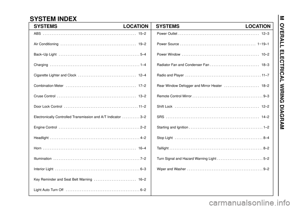
SYSTEM INDEX
M OVERALL ELECTRICAL WIRING DIAGRAM
SYSTEMS LOCATION SYSTEMS LOCATION
ABS 15±2. . . . . . . . . . . . . . . . . . . . . . . . . . . . . . . . . . . . . . . . . . . . . . . . . . . . .
Air Conditioning 19±2. . . . . . . . . . . . . . . . . . . . . . . . . . . . . . . . . . . . . . . . . . .
Back±Up Light 5±4. . . . . . . . . . . . . . . . . . . . . . . . . . . . . . . . . . . . . . . . . . . . . .
Charging 1±4. . . . . . . . . . . . . . . . . . . . . . . . . . . . . . . . . . . . . . . . . . . . . . . . . . .
Cigarette Lighter and Clock 12±4. . . . . . . . . . . . . . . . . . . . . . . . . . . . . . . . .
Combination Meter 17±2. . . . . . . . . . . . . . . . . . . . . . . . . . . . . . . . . . . . . . . .
Cruse Control 13±2. . . . . . . . . . . . . . . . . . . . . . . . . . . . . . . . . . . . . . . . . . . . .
Door Lock Control 11±2. . . . . . . . . . . . . . . . . . . . . . . . . . . . . . . . . . . . . . . . . .
Electronically Controlled Transmission and A/T Indicator 3±2. . . . . . . . . .
Engine Control 2±2. . . . . . . . . . . . . . . . . . . . . . . . . . . . . . . . . . . . . . . . . . . . . .
Headlight 4±2. . . . . . . . . . . . . . . . . . . . . . . . . . . . . . . . . . . . . . . . . . . . . . . . . . .
Horn 16±4. . . . . . . . . . . . . . . . . . . . . . . . . . . . . . . . . . . . . . . . . . . . . . . . . . . . .
Illumination 7±2. . . . . . . . . . . . . . . . . . . . . . . . . . . . . . . . . . . . . . . . . . . . . . . . .
Interior Light 6±3. . . . . . . . . . . . . . . . . . . . . . . . . . . . . . . . . . . . . . . . . . . . . . . .
Key Reminder and Seat Belt Warning 16±2. . . . . . . . . . . . . . . . . . . . . . . .
Light Auto Turn Off 6±2. . . . . . . . . . . . . . . . . . . . . . . . . . . . . . . . . . . . . . . . . . Power Outlet 12±3. . . . . . . . . . . . . . . . . . . . . . . . . . . . . . . . . . . . . . . . . . . . . .
Power Source 1~19±1. . . . . . . . . . . . . . . . . . . . . . . . . . . . . . . . . . . . . . . . . . .
Power Window 10±2. . . . . . . . . . . . . . . . . . . . . . . . . . . . . . . . . . . . . . . . . . . .
Radiator Fan and Condenser Fan 18±3. . . . . . . . . . . . . . . . . . . . . . . . . . . .
Radio and Player 11±7. . . . . . . . . . . . . . . . . . . . . . . . . . . . . . . . . . . . . . . . . . .
Rear Window Defogger and Mirror Heater 18±2. . . . . . . . . . . . . . . . . . . .
Remote Control Mirror 9±3. . . . . . . . . . . . . . . . . . . . . . . . . . . . . . . . . . . . . . . .
Shift Lock 12±2. . . . . . . . . . . . . . . . . . . . . . . . . . . . . . . . . . . . . . . . . . . . . . . .
SRS 14±2. . . . . . . . . . . . . . . . . . . . . . . . . . . . . . . . . . . . . . . . . . . . . . . . . . . . .
Starting and Ignition 1±2. . . . . . . . . . . . . . . . . . . . . . . . . . . . . . . . . . . . . . . . . .
Stop Light 8±4. . . . . . . . . . . . . . . . . . . . . . . . . . . . . . . . . . . . . . . . . . . . . . . . . .
Taillight 8±2. . . . . . . . . . . . . . . . . . . . . . . . . . . . . . . . . . . . . . . . . . . . . . . . . . . . .
Turn Signal and Hazard Warning Light 5±2. . . . . . . . . . . . . . . . . . . . . . . . . .
Wiper and Washer 9±2. . . . . . . . . . . . . . . . . . . . . . . . . . . . . . . . . . . . . . . . . . .
Page 4192 of 4592
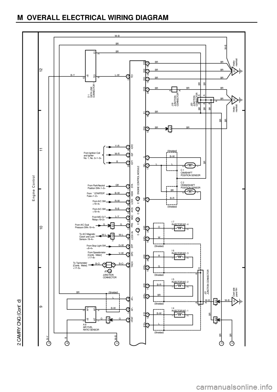
M OVERALL ELECTRICAL WIRING DIAGRAM
9
101112
2 CAMRY CNG (
Cont' d)
ECIntake
manif oldB±YBR BR W± B
BR BR BR
STP 4A
LOCK IN 18 C
PRS 10 D
B±OW± L
MG C 21 AL±Y
A/CS 10 AR±B
LOCK 15 AR± W
NSW 6AB±W
STA 11 AGR
IGT1 20 CB
IGF 3CW±R
IGT2 19 CY±RBR
10 IG3
W± L Fr om Ignit ion Coil
and Igniter
No. 1, No. 2< 1±3>
BRTE1 15 B
NE
1 2
C 2
CRANKSHAFT
POSITION SENSOR
1 2C 1
CA MSHAF T
POSITION SENSORNE ± GE03 E0 2 E01 SPD
E04
Intake
ma n i f o l dECL
B±RBRL B±W
(
Shielded) (
Shielded)BRBR
BR A
AA
A
A J20
JUNCTION
CONNE CTOR
BR BR BR BR
TE1 E1+BL±W
To Tac hometer
[Comb. Met er]
< 17±5>To A/ C Magnetic
Clutch and Loc k
Sens or< 19±4> Fr om A/C Dual
Pressure SW< 19±4>Fr om MG CL T
Relay< 19±2>Fro m A/C SW
< 19±4> Fro m A/C SW
< 19±4> From º STARTERº
Fuse< 1±2>Fr om Park/ Neutral
Posit ion SW< 1±2>12
8 D 1
DA TA LI NK
CONNECTOR 1
3
E1
BR
ENGI NE CONT ROL MODULE
IG3 6
E ngine Control
BR
BR
BR
G L
A 8
AI R FUEL
RA TI O SE NS ORHTA F 2A
AF± 14 B
AF+ 6B 14 23
B±W (
Shielded)
HT AF±+B AF+ A
B
D
EB B±Y
C 16 A 13 C 5 C 17 C 4
BRA16 B 22 C 13 C
JUNCTION
CONNECTORJ23
TACH
A
, E 5 E 4 A B , E 6 C , E 7 D
BRBR CW± B1IG1G G
7IG1
G
9A 8A FA
FA
B±O From Stop Light SW
< 8±4>
V±W Fr om Speedomet er
[Comb. Meter]
< 17±8>G±W
2 1 12 C 2C
I 4
INJECTOR NO. 1
L B±W
(
Shielded)
2 1 11 C 1C
I 5
INJECTOR NO. 2
BR B±R
(
Shielded)
2 1 25 C 15 C
I 6
INJECTOR NO. 3
GR
(
Shielded)
2 1 24 C 14 C
I 7
INJECTOR NO. 4
WO
(
Shielded)
4IG1
IHCowl side
panel RH A AAA
A
W± B W± B
J21
J UNCTI ON CONNECTOR3IG1
BR
26 C
A A
J18
JUNCT I ON
CONNECTOR
BRBR BR
W±B BR
BREO5 #40 #40+ #30 #30+ # 10+ # 10 # 20+ # 20
Page 4236 of 4592
B
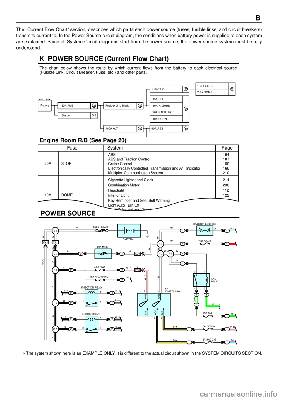
The ºCurrent Flow Chartº section, describes which parts each power source (fuses, fusible links, and circuit breakers)
transmits current to. In the Power Source circuit diagram, the conditions when battery power is supplied to each system
are explained. Since all System Circuit diagrams start from the power source, the power source system must be fully
understood.
Theft Deterrent and Door Lock Control
K POWER SOURCE (Current Flow Chart)
11
1
EA1 1EA2 3
7
EB16
E 6
E 7I 2I 2
I 2
E 7
E 7
E 7
2
1
1
2
2
2
2
2
B
B
W W
B B B B BW±B
B
B
B B±O
B±W
W±B
B±W STARTER RELAY INJECTION RELAY15A HAZ±RADIO7.5A AM250A MAIN 1.25B FL MAIN
BATTERY
WWW
W W W
R W±L
W
W
G±W
G
15A TAIL
20A DEFOG
15A RAD CIGTA I L
RELAY 7.5A DOME 40A DOOR LOCK CB
2 1
1 2
4 8
2 3
3 4
G
W±R
P±L B±Y
B±Y
W±R
AM2 IG2
ACC
IG1AM1W W
W±R
W W
W±B
21
1
1
1
1
2
2
2
2
3
4
3
4 1
2
1
22
1
11
1
IGNITION SW I 8
Battery
30A AM2
2
Starter S 220A RADIO NO.1
10A HORN
15A EFI
7.5A DOMEShort Pin
10A HAZARD
The chart below shows the route by which current flows from the battery to each electrical source
(Fusible Link, Circuit Breaker, Fuse, etc.) and other parts.
Engine Room R/B (See Page 20)
ABS
ABS and Traction Control
Cruise Control
Electronically Controlled Transmission and A/T Indicator
Multiplex Communication System
Cigarette Lighter and Clock
Key Reminder and Seat Belt Warning STOP
Fuse Page
194
214
11 2
System
DOME 20A
10ACombination Meter
Headlight
Interior Light
2
2
6 100A ALT
EB1
POWER SOURCE
Light Auto Turn Off187
180
166
210
230
122
10A ECU±B
5 60A ABS
2
6 Fusible Link Block2
* The system shown here is an EXAMPLE ONLY. It is different to the actual circuit shown in the SYSTEM CIRCUITS SECTION.
Page 4276 of 4592
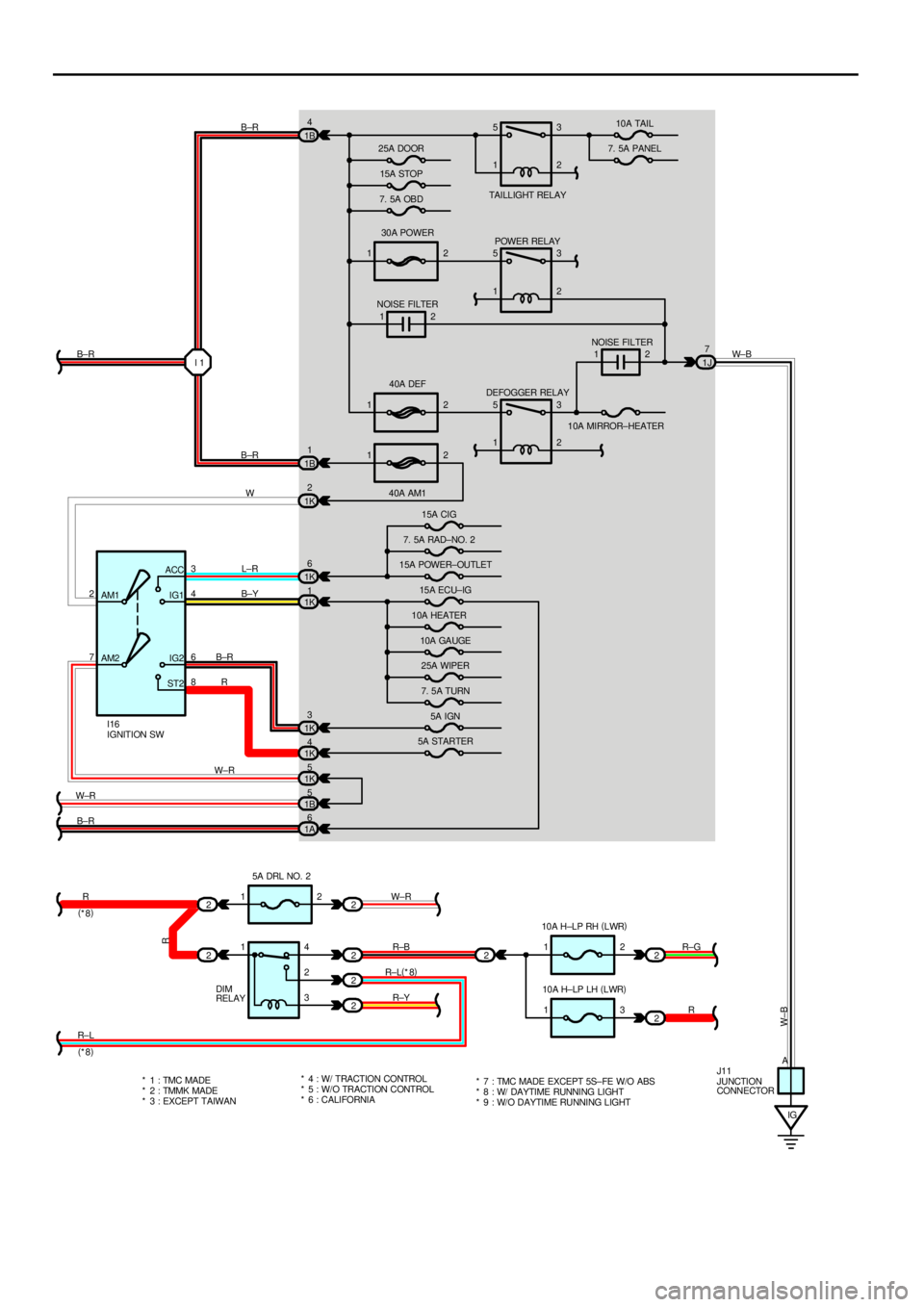
1230A POWER
1240A DEF
12
40A AM1 1B4
1B1
1K2
1K6
1K1
1K3
1K4
1K5
1B5
2
221J7
2
2
2
22
2 AM1
AM2 7 23
6 ACC
IG1
IG2
ST24
8I 1
12
IG 12
13 25A DOOR
15A STOP
7. 5A OBDTAI LL IGHT REL AY10A TAIL
7. 5A PANEL
POWER RELAY
NOISE FILTER
NOISE FILTER
DEFOGGER RELAY
10A MIRROR±HEATER
15A CIG
7. 5A RAD±NO. 2
15A POWER±OUTLET
15A ECU±IG
10A HEATER
10A GAUGE
25A WIPER
7. 5A TURN
5A IGN
5A STARTER
5A DRL NO. 2
DIM
RELAY10A H±LP RH (
LWR)
10A H±LP LH (
LWR)
JUNCTION
CONNECTOR IGNITION SW I16
J11 B±R
B±R
W B±R
W± B
L±R
B±Y
B±R
R1
1 5
1
5
1
5
13
2
3
2
2
2
3
2
* 1 : TMC MADE
* 2 : TMMK MADE
* 3 : EXCEPT TAIWAN* 4 : W/ TRACTION CONTROL
* 5 : W/ O TRACTI ON CONTROL W±R
R
R±L W±R
(
*8)
(
*8)14
2
3W±R
R±B
R±L(
*8)
R±YR±G
R
A
W±B
1A6
B±R
R
* 6 : CALIFORNIA* 7 : TMC MADE EXCEPT 5S±FE W/O ABS
* 8 : W/ DAYTIME RUNNING LIGHT
* 9 : W/O DAYTIME RUNNING LIGHT