Page 3351 of 4592
THROTTLE BODY
SF±29
1462 Author�: Date�:
THROTTLE BODY
ON±VEHICLE INSPECTION
1. INSPECT THROTTLE B")
B01277
Move
SF0DN±03
B00525
P
R
E
B01278
Disconnect
Vacuum
B01282
VTA
E2
VCOhmmeter
± SFI (5S±FE)THROTTLE BODY
SF±29
1462 Author�: Date�:
THROTTLE BODY
ON±VEHICLE INSPECTION
1. INSPECT THROTTLE BODY
(a) Check that the throttle linkage moves smoothly.
(b) Check the vacuum at each port.
�Start the engine.
�Check the vacuum with your finger.
Port nameAt idleOther than idle
Mark EVacuumVacuum
Mark PNo vacuumVacuum
Mark RNo vacuumNo vacuum
2. INSPECT THROTTLE POSITION SENSOR
(a) Disconnect the sensor connector.
(b) Disconnect the vacuum hose from the throttle opener.
(c) Apply vacuum to the throttle opener.
(d) Using an ohmmeter, measure the resistance between
each terminal.
Clearance between
lever and stop screwBetween
terminalsResistance
0 mm (0 in.)VTA ± E20.2 ± 5.7 kW
Throttle valve fully
openVTA ± E22.0 ± 10.2 kW
±VC ± E22.5 ± 5.9 kW
(e) Reconnect the vacuum hose to the throttle opener.
(f) Reconnect the sensor connector.
3. INSPECT THROTTLE OPENER
(a) Allow the engine to warm up to normal operating tempera-
ture.
Page 3390 of 4592
SFI SYSTEM
1501 Author�: Date�:
(b) When installing the battery, be especially careful not to in-
correctly connect the positive")
FI2553
SST
S04600
Fuel
Pump
Connector
S05039
Plug
SF±2
± SFI (1MZ±FE)SFI SYSTEM
1501 Author�: Date�:
(b) When installing the battery, be especially careful not to in-
correctly connect the positive (+) and negative (±) cables.
(c) Do not permit parts to receive a severe impact during re-
moval or installation. Handle all SFI parts carefully, espe-
cially the ECM.
(d) Be careful during troubleshooting as there are numerous
transistor circuit, and even slight terminal contact can
cause further troubles.
(e) Do not open the ECM cover.
(f) When inspecting during rainy weather, take care to pre-
vent entry of water. Also, when washing the engine
compartment, prevent water from getting on the SFI parts
and wiring connectors.
(g) Parts should be replaced as an assembly.
(h) Care should be taken when pulling out and inserting wir-
ing connectors.
(1) Release the lock and pull out the connector, pulling
on the connectors.
(2) Fully insert the connector and check that it is locked.
(i) Use SST for inspection or test of the injector or its wiring
connector.
SST 09842±30070
8. FUEL SYSTEM
(a) When disconnecting the high fuel pressure line, a large
amount of gasoline will spill out, so observe these proce-
dures:
(1) Disconnect the fuel pump connector.
(2) Start the engine. After the engine has stopped on
its own, turn the ignition switch to LOCK.
(3) Put a container under the connection.
(4) Slowly loosen the connection.
(5) Disconnect the connection.
(6) Plug the connection with a rubber plug.
Page 3395 of 4592

Pipe
SST
(Hose)SST
± SFI (1MZ±FE)FUEL PUMP
SF±7
1506 Author�: Date�:
(d) Remove the fuel hose clamp.
(e) D")
S06086
Fuel Hose
Clamp
S05352
S05364
SST
SST
Retainer
No.1 Fuel
Fuel Tube
Connector (Hose)
Pipe
SST
(Hose)SST
± SFI (1MZ±FE)FUEL PUMP
SF±7
1506 Author�: Date�:
(d) Remove the fuel hose clamp.
(e) Disconnect the No.1 fuel pipe (fuel tube connector) from
the fuel filter outlet.
CAUTION:
�Perform disconnecting operations of the fuel tube
connector (quick type) after observing the precau-
tions. (See page SF±1)
�As there is retained pressure in the fuel pipe line, pre-
vent it from splashing inside the engine compart-
ment.
(f) Install SST (pressure gauge) as shown in the illustration
by using SST and fuel tube connector.
SST 09268±41047, 09268±41250, 09268±45012
(g) Wipe off any splattered gasoline.
(h) Reconnect the negative (±) terminal cable to the battery.
(i) Connect the TOYOTA hand held tester to the DLC3.
(See step 1. check fuel pump operation (a) to (e))
(j) Measure the fuel pressure.
Fuel pressure:
301 ± 347 kPa (3.1 ± 3.5 kgf/cm
2, 44 ± 50 psi)
If pressure is high, replace the fuel pressure regulator.
If pressure is low, check these parts:
Fuel hoses and connections
Fuel pump
Fuel filter
Fuel pressure regulator
(k) Disconnect the TOYOTA hand±held tester from the
DLC3.
(l) Start the engine.
(m) Measure the fuel pressure at idle.
Fuel pressure:
301 ± 347 kPa (3.1 ± 3.5 kgf/cm
2, 44 ± 50 psi)
(n) Stop the engine.
(o) Check that the fuel pressure remains as specified for 5
minutes after the engine has stopped.
Fuel pressure:
147 kPa (1.5 kgf/cm
2, 21 psi) or more
If pressure is not as specified, check the fuel pump, pressure
regulator and/or injectors.
Page 3425 of 4592
THROTTLE BODY
SF±37
1536 Author�: Date�:
THROTTLE BODY
ON±VEHICLE INSPECTION
1. INSPECT THROTTLE BODY
Check th")
S04593
SF07T±03
S04536
Vacuum
VTAOhmmeter
E2
VC
S04604
Plug
Disconnect
± SFI (1MZ±FE)THROTTLE BODY
SF±37
1536 Author�: Date�:
THROTTLE BODY
ON±VEHICLE INSPECTION
1. INSPECT THROTTLE BODY
Check that the throttle linkage moves smoothly.
2. INSPECT THROTTLE POSITION SENSOR
(a) Disconnect the sensor connector.
(b) Disconnect the vacuum hose from the throttle body.
(c) Apply vacuum to the throttle opener.
(d) Using an ohmmeter, measure the resistance between
each terminal.
Resistance:
Throttle valve
conditionBetween
terminalsResistance
Fully closedVTA ± E20.2 ± 6.3 kW
Fully openVTA ± E22.0 ± 10.2 kW
±VC ± E22.5 ± 5.9 kW
(e) Reconnect the vacuum hose to the throttle body.
(f) Reconnect the sensor connector.
3. INSPECT THROTTLE OPENER
(a) Allow the engine to warm up to normal operating tempera-
ture.
(b) Check idle speed.
Idle speed: 700 ± 50 rpm
(c) Disconnect the vacuum hose from the throttle opener,
and plug the hose end.
(d) Check the throttle opener setting speed.
Throttle opener setting speed: 900 ± 1,950 rpm
If the throttle opener setting is not as specified, replace the
throttle body.
(e) Stop the engine.
(f) Reconnect the vacuum hose to the throttle opener.
(g) Start the engine and check that the idle speed returns to
the correct speed.
Page 3431 of 4592
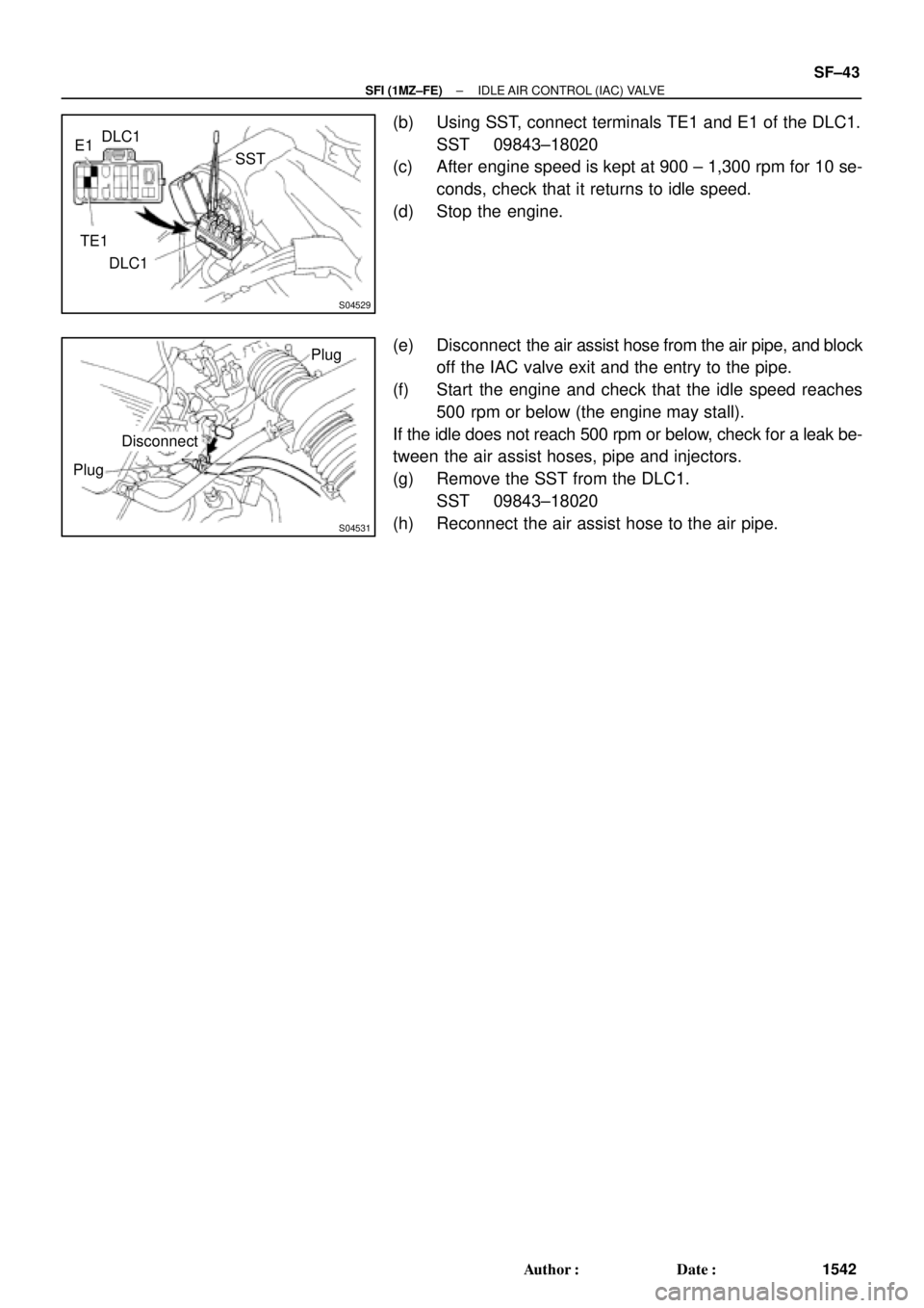
S04529
E1DLC1
SST
TE1
DLC1
S04531
DisconnectPlug
Plug
± SFI (1MZ±FE)IDLE AIR CONTROL (IAC) VALVE
SF±43
1542 Author�: Date�:
(b) Using SST, connect terminals TE1 and E1 of the DLC1.
SST 09843±18020
(c) After engine speed is kept at 900 ± 1,300 rpm for 10 se-
conds, check that it returns to idle speed.
(d) Stop the engine.
(e) Disconnect the air assist hose from the air pipe, and block
off the IAC valve exit and the entry to the pipe.
(f) Start the engine and check that the idle speed reaches
500 rpm or below (the engine may stall).
If the idle does not reach 500 rpm or below, check for a leak be-
tween the air assist hoses, pipe and injectors.
(g) Remove the SST from the DLC1.
SST 09843±18020
(h) Reconnect the air assist hose to the air pipe.
Page 3469 of 4592
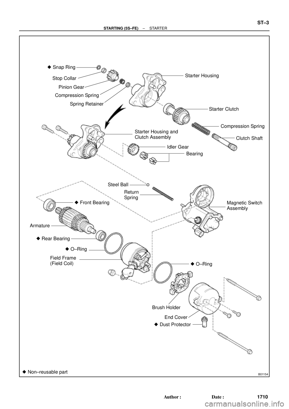
B01154
� Snap Ring
Starter Housing
Starter Clutch
Compression Spring
Clutch Shaft
Starter Housing and
Clutch Assembly
Idler Gear
Bearing Stop Collar
Pinion Gear
Compression Spring
Spring Retainer
Steel Ball
Return
Spring
� Front Bearing
Armature
� O±Ring
Field Frame
(Field Coil)
End Cover Brush Holder � Rear Bearing
� Dust Protector
� Non±reusable part
Magnetic Switch
Assembly
� O±Ring
± STARTING (5S±FE)STARTER
ST±3
1710 Author�: Date�:
Page 3477 of 4592
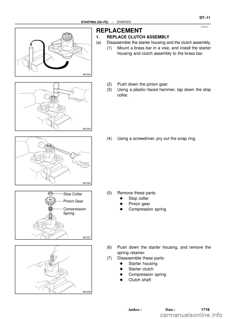
ST03M±03
B01224
B01225
B01226
B01227
Stop Collar
Pinion Gear
Compression
Spring
B01228
± STARTING (5S±FE)STARTER
ST±11
1718 Author�: Date�:
REPLACEMENT
1. REPLACE CLUTCH ASSEMBLY
(a) Disassemble the starter housing and the clutch assembly.
(1) Mount a brass bar in a vise, and install the starter
housing and clutch assembly to the brass bar.
(2) Push down the pinion gear.
(3) Using a plastic±faced hammer, tap down the stop
collar.
(4) Using a screwdriver, pry out the snap ring.
(5) Remove these parts:
�Stop collar
�Pinion gear
�Compression spring
(6) Push down the starter housing, and remove the
spring retainer.
(7) Disassemble these parts:
�Starter housing
�Starter clutch
�Compression spring
�Clutch shaft
Page 3478 of 4592
B01229
Starter Housing
Starter
ClutchCompression
Spring
Clutch
Shaft
B01230
B01231B01670
Spring
Compression PinionStop
Collar
Gear
Spring
Retainer
B01232
B01233
ST±12
± STARTING (5S±FE)STARTER
1719 Author�: Date�:
(b) Assemble the starter housing and the clutch assembly
(1) Assemble these parts:
�Starter housing
�Starter clutch
�Compression spring
�Clutch shaft
(2) Mount a brass bar in a vise, install the starter hous-
ing and clutch assembly to the brass bar.
(3) Push down the starter housing, and install these
parts:
�Spring retainer
�Compression spring
�Pinion gear
�Stop collar
(4) Push down the pinion gear.
(5) Using snap ring pliers, install a new snap ring.
(6) Using pliers, compress the snap ring.
(7) Check that the snap ring fits correctly.
STARTER
1719")