Page 4130 of 4592

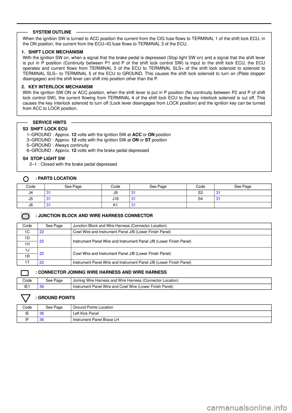
When the ignition SW is turned to ACC position the current from the CIG fuse flows to TERMINAL 1 of the shift lock ECU, in
the ON position, the current from the ECU±IG fuse flows to TERMINAL 3 of the ECU.
1. SHIFT LOCK MECHANISM
With the ignition SW on, when a signal that the brake pedal is depressed (Stop light SW on) and a signal that the shift lever
is put in P position (Continuity between P1 and P of the shift lock control SW) is input to the shift lock ECU, the ECU
operates and current flows from TERMINAL 3 of the ECU to TERMINAL SLS+ of the shift lock solenoid to solenoid to
TERMINAL SLS± to TERMINAL 5 of the ECU to GROUND. This causes the shift lock solenoid to turn on (Plate stopper
disengages) and the shift lever can shift into position other than the P.
2. KEY INTERLOCK MECHANISM
With the ignition SW ON or ACC position, when the shift lever is put in P position (No continuity between P2 and P of shift
lock control SW), the current flowing from TERMINAL 4 of the shift lock ECU to the key interlock solenoid is cut off. This
causes the key interlock solenoid to turn off (Lock lever disengages from LOCK position) and the ignition key can be turned
from ACC to LOCK position.
S3 SHIFT LOCK ECU
1±GROUND : Approx. 12 volts with the ignition SW at ACC or ON position
3±GROUND : Approx. 12 volts with the ignition SW at ON or ST position
5±GROUND : Always continuity
6±GROUND : Approx. 12 volts with the brake pedal depressed
S4 STOP LIGHT SW
2±1 : Closed with the brake pedal depressed
: PARTS LOCATION
CodeSee PageCodeSee PageCodeSee Page
J431J931S331
J531J1631S431
J631K131
������ ���: JUNCTION BLOCK AND WIRE HARNESS CONNECTOR
CodeSee PageJunction Block and Wire Harness (Connector Location)
1C22Cowl Wire and Instrument Panel J/B (Lower Finish Panel)
1D22Instrument Panel Wire and Instrument Panel J/B (Lower Finish Panel)1H22Instrument Panel Wire and Instrument Panel J/B (Lower Finish Panel)
1J22Cowl Wire and Instrument Panel J/B (Lower Finish Panel)1R22Cowl Wire and Instrument Panel J/B (Lower Finish Panel)
1T22Instrument Panel Wire and Instrument Panel J/B (Lower Finish Panel)
: CONNECTOR JOINING WIRE HARNESS AND WIRE HARNESS
CodeSee PageJoining Wire Harness and Wire Harness (Connector Location)
IE136Instrument Panel Wire and Cowl Wire (Lower Finish Panel)
: GROUND POINTS
CodeSee PageGround Points Location
IE36Left Kick Panel
IF36Instrument Panel Brace LH
SYSTEM OUTLINE
SERVICE HINTS
Page 4133 of 4592
CIGARETTE LIGHTER AND CLOCK
15A
CIG
1J 67. 5A
PANEL FROM POWER SOURCE SYSTEM (
SEE PAGE 44)
1D 57. 5A
DOME
2J 12 1T 1
1G 81W 1
IFIE A A
B A
B D
A E
1
A2 4 A
A
A1 3 A
2
W± BP±L
P±L P±L
W±B W± BG
R
RRG
CLOCK CIGARETTE
LIGHTERJUNCTION
CONNECTOR
C 7J 5
C 9
JUNCTION
CONNECTORJUNCTION
CONNECTOR
J 9J 42 1
R±Y
DIODE
(
DOME) D 5 J28
JUNCTION
CONNECTORB A, J29
J16
JUNCTION
CONNECTORB A, J17
Page 4134 of 4592

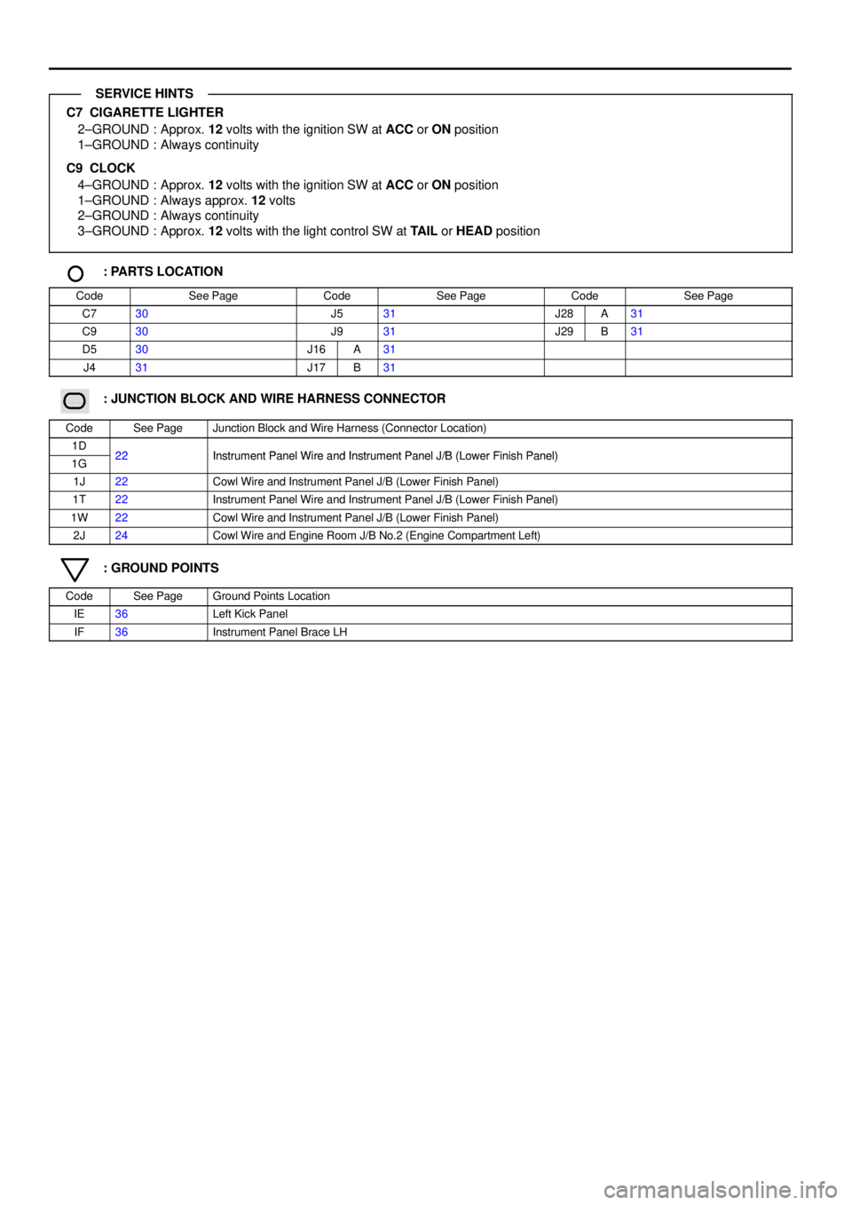
C7 CIGARETTE LIGHTER
2±GROUND : Approx. 12 volts with the ignition SW at ACC or ON position
1±GROUND : Always continuity
C9 CLOCK
4±GROUND : Approx. 12 volts with the ignition SW at ACC or ON position
1±GROUND : Always approx. 12 volts
2±GROUND : Always continuity
3±GROUND : Approx. 12 volts with the light control SW at TAIL or HEAD position
: PARTS LOCATION
CodeSee PageCodeSee PageCodeSee Page
C730J531J28A31
C930J931J29B31
D530J16A31
J431J17B31
������ ���: JUNCTION BLOCK AND WIRE HARNESS CONNECTOR
CodeSee PageJunction Block and Wire Harness (Connector Location)
1D22Instrument Panel Wire and Instrument Panel J/B (Lower Finish Panel)1G22Instrument Panel Wire and Instrument Panel J/B (Lower Finish Panel)
1J22Cowl Wire and Instrument Panel J/B (Lower Finish Panel)
1T22Instrument Panel Wire and Instrument Panel J/B (Lower Finish Panel)
1W22Cowl Wire and Instrument Panel J/B (Lower Finish Panel)
2J24Cowl Wire and Engine Room J/B No.2 (Engine Compartment Left)
: GROUND POINTS
CodeSee PageGround Points Location
IE36Left Kick Panel
IF36Instrument Panel Brace LH
SERVICE HINTS
Page 4135 of 4592
KEY REMINDER AND SEAT BELT WARNING
2 1
12J 12 1D2
1T 3
1M 51S71S4
1J 71M 3DD
1W 1
IFBK
R±W
R L±B W± B
R±G W±B
R±L R±LFROM POWER SOURCE SYSTEM (
SEE PAGE 44)
10A
GAU GE7. 5A
DOME
SEAT BELT
WARNING LIGHT
[COMB. METER]JUNCTION
CONNECTOR
UNLOCK
WARNING SW
DOOR COURTESY
SW FRONT LH J 3
U 1
D 7
A
JUNCTION
CONNECTOR J34 A
JUNCTION
CONNECTOR J 9971
8 6 5 10C 7
A 4
BUZZER C C10 A , C12
2 1
R±Y W±B
BUCKLE
SW LH B 5 25A
DOOR
1D 1
B C
A A
A 13
J31
JUNCTION
CONNECTORB A, J32L±W L±W
I12
INTEGRATION RELAYA
Page 4136 of 4592

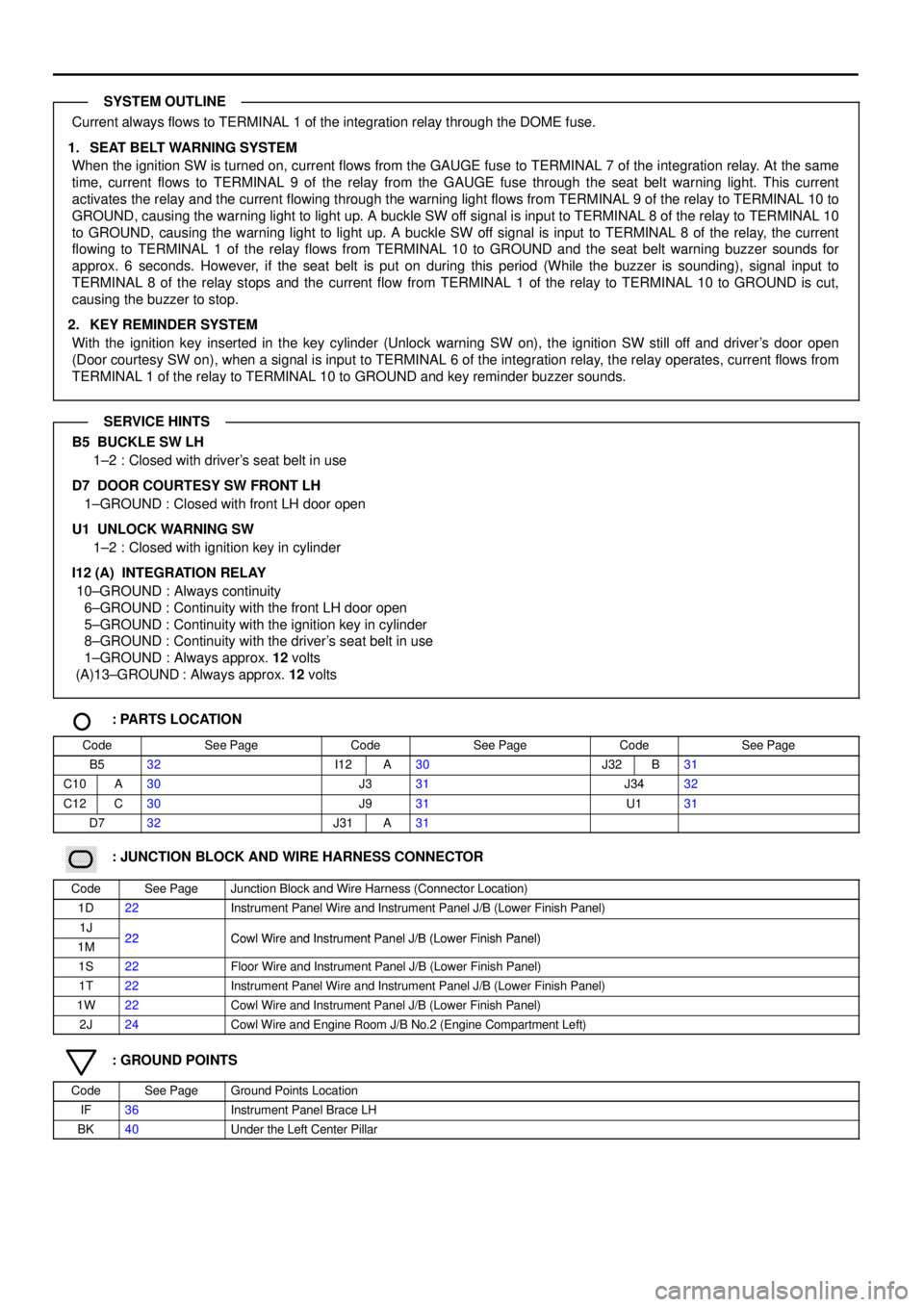
Current always flows to TERMINAL 1 of the integration relay through the DOME fuse.
1. SEAT BELT WARNING SYSTEM
When the ignition SW is turned on, current flows from the GAUGE fuse to TERMINAL 7 of the integration relay. At the same
time, current flows to TERMINAL 9 of the relay from the GAUGE fuse through the seat belt warning light. This current
activates the relay and the current flowing through the warning light flows from TERMINAL 9 of the relay to TERMINAL 10 to
GROUND, causing the warning light to light up. A buckle SW off signal is input to TERMINAL 8 of the relay to TERMINAL 10
to GROUND, causing the warning light to light up. A buckle SW off signal is input to TERMINAL 8 of the relay, the current
flowing to TERMINAL 1 of the relay flows from TERMINAL 10 to GROUND and the seat belt warning buzzer sounds for
approx. 6 seconds. However, if the seat belt is put on during this period (While the buzzer is sounding), signal input to
TERMINAL 8 of the relay stops and the current flow from TERMINAL 1 of the relay to TERMINAL 10 to GROUND is cut,
causing the buzzer to stop.
2. KEY REMINDER SYSTEM
With the ignition key inserted in the key cylinder (Unlock warning SW on), the ignition SW still off and driver's door open
(Door courtesy SW on), when a signal is input to TERMINAL 6 of the integration relay, the relay operates, current flows from
TERMINAL 1 of the relay to TERMINAL 10 to GROUND and key reminder buzzer sounds.
B5 BUCKLE SW LH
1±2 : Closed with driver's seat belt in use
D7 DOOR COURTESY SW FRONT LH
1±GROUND : Closed with front LH door open
U1 UNLOCK WARNING SW
1±2 : Closed with ignition key in cylinder
I12 (A) INTEGRATION RELAY
10±GROUND : Always continuity
6±GROUND : Continuity with the front LH door open
5±GROUND : Continuity with the ignition key in cylinder
8±GROUND : Continuity with the driver's seat belt in use
1±GROUND : Always approx. 12 volts
(A)13±GROUND : Always approx. 12 volts
: PARTS LOCATION
CodeSee PageCodeSee PageCodeSee Page
B532I12A30J32B31
C10A30J331J3432
C12C30J931U131
D732J31A31
������ ���: JUNCTION BLOCK AND WIRE HARNESS CONNECTOR
CodeSee PageJunction Block and Wire Harness (Connector Location)
1D22Instrument Panel Wire and Instrument Panel J/B (Lower Finish Panel)
1J22Cowl Wire and Instrument Panel J/B (Lower Finish Panel)1M22Cowl Wire and Instrument Panel J/B (Lower Finish Panel)
1S22Floor Wire and Instrument Panel J/B (Lower Finish Panel)
1T22Instrument Panel Wire and Instrument Panel J/B (Lower Finish Panel)
1W22Cowl Wire and Instrument Panel J/B (Lower Finish Panel)
2J24Cowl Wire and Engine Room J/B No.2 (Engine Compartment Left)
: GROUND POINTS
CodeSee PageGround Points Location
IF36Instrument Panel Brace LH
BK40Under the Left Center Pillar
SYSTEM OUTLINE
SERVICE HINTS
Page 4146 of 4592
5A
STARTER FROM POWER SOURCE SYSTEM (
SEE PAGE 44)
1J 3
IH1 5IC2 5 IE2 5IF117 IE23
IJ2 3B 2
B 5C10 A4C4C11 A3B7A12
EBB C
A B
IE1 6
11
IE1 7
2 1
IF
B±W Y±B Y±B
O O
R±W
R±L
P±L
Y±G P±L P±L W±B
Y±G
R±W R±W R±W
R±W W±B
B±W
PARK/NEUTRAL
POSITION SW P 1
OIL PRESSURE
SW O 1
WASHER LEVEL
WARNING SW W 1
JUNCTION
CONNECTOR J 1
BRAKE FLUID
LEVEL WARNING SW B 1
JUNCTION
CONNECTOR J 9
G±O
B
5
B 6
2B B
B
OI L
CRUISE
SEAT BELT
ABS
WASHER LEVEL
REAR LIGHTS
BRAKE
BULB
CHECK
RELAY
O/ D OFF
JUNCTION
CONNECTOR J22
P
N
A
TO CRUISE
CONTROL ECU
TO I NTEGRATION
RELAY
TO ABS ECU
TO LI GHT
FAI LURE
SENSOR
B±O
TO O/ D
MAIN SW
J 6
JUNCTION
CONNECTORB A, J 7
C10
COMBINATION METERB A, C11 C, C12
GR
IG211
IG210 B±W
GRGR
1
R±W
PARKING
BRAKE SW P 3
Page 4147 of 4592
COMBINATION METER
5A
IGN
1T 8 FROM POWER SOURCE SYSTEM (
SEE PAGE 44)
B 1C1A13 A9A8A10 A7A6C13
B 4B16C 12
IEW±B
W±BG
W±BG
B
G± B
G± Y
B±R
G± W
R±B
R
B±R
O
Y
G Y
W± B W± B
G
B
A2
A31
A
AETILL FROM HAZARD SW OR
TURN SIGNAL SW
[COMB. SW]FROM A/T INDICATOR LIGHT SW
[PARK/NEUTRAL POSITION SW]
TO GENERATORTURN LH
TURN RH
CHARGE
P
R
N
D
2
L
ILLUMINATION
RHEOSTAT R 6
JUNCTION
CONNECTOR J 4C10
COMBINATION METERB A, C11 C, C12 A 11
D D
JUNCTION
CONNECTOR J16
Page 4161 of 4592
I GROUND POINT
FRONT TURN SIGNAL
LIGHT AND PARKING
LIGHT LH
FRONT TURN SIGNAL
LIGHT AND PARKING
LIGHT RH
RADIATOR FAN
MOTOR
WASHER LEVEL
WARNING SW
WATER TEMP. SW
NO. 1
FAN NO. 2 RELAYABS SOL RELAY
FAN NO. 3 RELAY
HTR RELAY
ENGINE MAIN RELAY
EFI RELAY
FRONT WIPER MOTORABS ACTUATOR
1
1
1EA12
E 2 E 2
E 2
E 2
E 2
E 2
E 2
2J 10
2F4
2C 5
EB3
E 1
EA W±B W±B W±B W±B W±B
W± B
W±B
W±B
W±BW±B
W±B W± B W±B W±B W± B W±B W± B
W±B
W±B
W± B
W±B
W±B
W±B