Page 1148 of 4592
WATER PUMP
1582 Author�: Date�:
INSTALLATION
1. INSTALL WATER PUMP TO WATER PUMP COVER
Install a new gasket and the")
CO06B±03
N00918
S06015
Connect
Z19283
1
3
2
S05924
S05599
CO±8
± COOLING (5S±FE)WATER PUMP
1582 Author�: Date�:
INSTALLATION
1. INSTALL WATER PUMP TO WATER PUMP COVER
Install a new gasket and the water pump with the 3 bolts.
Torque: 8.8 N´m (90 kgf´cm, 78 in.´lbf)
2. INSTALL WATER PUMP AND WATER PUMP COVER
ASSEMBLY
(a) Install new O±ring and gasket to water pump cover.
(b) Install a new O±ring to the water bypass pipe.
(c) Apply soapy water to the O±ring on the water bypass
pipe.
(d) Connect the water pump cover to the water bypass pipe.
Do not install the nuts yet.
(e) Install the water pump with the 3 bolts. Tighten the bolts
in the sequence shown.
Torque: 8.8 N´m (90 kgf´cm, 78 in.´lbf)
(f) Install the 2 nuts holding the water pump cover to the wa-
ter bypass pipe.
Torque: 9.3 N´m (95 kgf´cm, 82 in.´lbf)
3. INSTALL GENERATOR DRIVE BELT ADJUSTING BAR
(a) Install the adjusting bar with the bolt.
Torque: 22 N´m (224 kgf´cm, 16 ft´lbf)
(b) Install the engine wire clamp to the adjusting bar.
(c) Install the crankshaft position sensor connector to the
bracket on the adjusting bar.
4. w/ Oil Cooler:
INSTALL A/C COMPRESSOR (See page EM±75)
5. INSTALL NO.2 IDLER PULLEY (See page EM±23)
Page 1151 of 4592
CO06D±03
S05322
± COOLING (5S±FE)THERMOSTAT
CO±11
1585 Author�: Date�:
REMOVAL
HINT:
Removal of the thermostat would have an adverse effect, caus-
ing a lowering of cooling efficiency. Do not remove the thermo-
stat, even if the engine tends to overheat.
1. DRAIN ENGINE COOLANT
2. w/ Oil Cooler:
REMOVE OIL FILTER (See page LU±2)
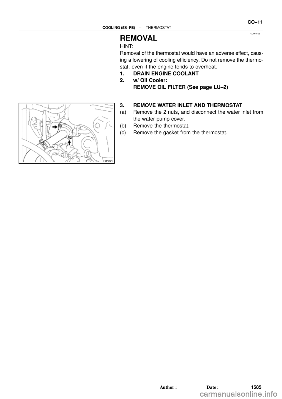
3. REMOVE WATER INLET AND THERMOSTAT
(a) Remove the 2 nuts, and disconnect the water inlet from
the water pump cover.
(b) Remove the thermostat.
(c) Remove the gasket from the thermostat.
Page 1153 of 4592
CO0SN±01
P13611
Protrusion
Jiggle
Valve5°5°
S05322
± COOLING (5S±FE)THERMOSTAT
CO±13
1587 Author�: Date�:
INSTALLATION
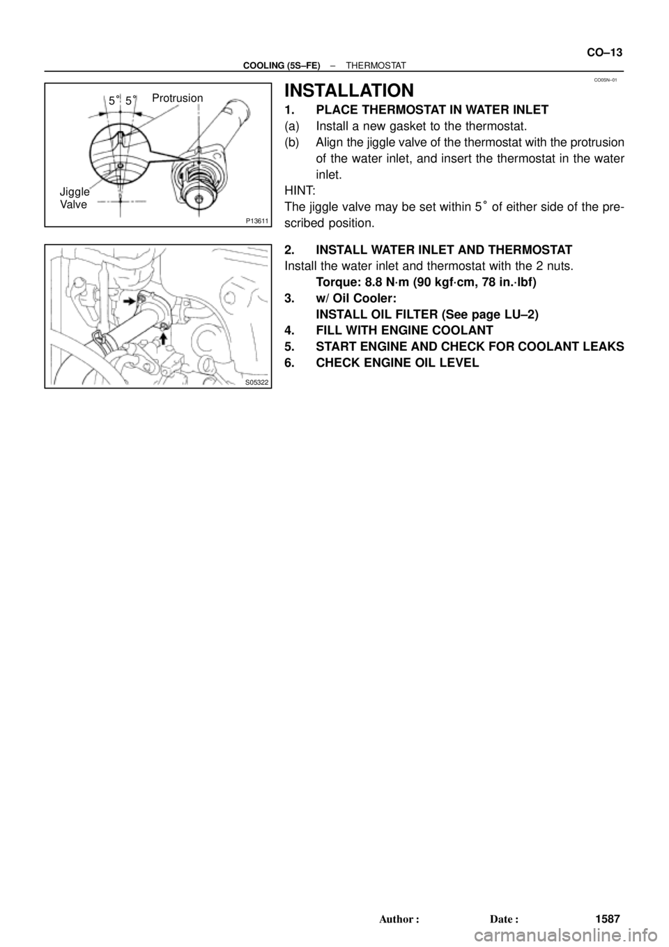
1. PLACE THERMOSTAT IN WATER INLET
(a) Install a new gasket to the thermostat.
(b) Align the jiggle valve of the thermostat with the protrusion
of the water inlet, and insert the thermostat in the water
inlet.
HINT:
The jiggle valve may be set within 5° of either side of the pre-
scribed position.
2. INSTALL WATER INLET AND THERMOSTAT
Install the water inlet and thermostat with the 2 nuts.
Torque: 8.8 N´m (90 kgf´cm, 78 in.´lbf)
3. w/ Oil Cooler:
INSTALL OIL FILTER (See page LU±2)
4. FILL WITH ENGINE COOLANT
5. START ENGINE AND CHECK FOR COOLANT LEAKS
6. CHECK ENGINE OIL LEVEL
Page 1158 of 4592
RADIATOR
1592 Author�: Date�:
REMOVAL
1. DRAIN ENGINE COOLANT
2. REMOVE RADIATOR ASSEMBLY
(a) Disconnect the No.1 electric cooling fan connector.
(b) Disconn")
CO06J±04
S05955
CO±18
± COOLING (5S±FE)RADIATOR
1592 Author�: Date�:
REMOVAL
1. DRAIN ENGINE COOLANT
2. REMOVE RADIATOR ASSEMBLY
(a) Disconnect the No.1 electric cooling fan connector.
(b) Disconnect the No.2 electric cooling fan connector.
(c) Disconnect the ECT switch connector for the electric cool-
ing fan.
(d) Disconnect the upper radiator hose from the radiator.
(e) Disconnect the lower radiator hose from the water inlet.
(f) Disconnect the radiator reservoir hose from the radiator.
(g) A/T:
Disconnect the 2 oil cooler hoses from the oil cooler pipes.
(h) Remove the 2 bolts and 2 upper radiator supports.
(i) Remove the radiator assembly.
(j) Remove the 2 lower radiator supports.
(k) Remove the lower radiator hose from the radiator.
(l) A/T:
Remove the 2 oil cooler hoses from the radiator.
3. REMOVE NO.1 ELECTRIC COOLING FAN FROM RA-
DIATOR
(a) Disconnect the ECT switch connector for the cooling fan.
(b) Disconnect the ECT switch wire clamp for the cooling fan
from the bracket of the radiator.
(c) Remove the 2 bolts and cooling fan.
4. REMOVE NO.2 ELECTRIC COOLING FAN FROM RA-
DIATOR
Remove the 2 bolts and cooling fan.
Page 1163 of 4592
RADIATOR
CO±23
1597 Author�: Date�:
INSTALLATION
1. INSTALL NO.1 ELECTRIC COOLING FAN TO RADIA-
TOR
(a) Attach the lower side of the cooling fan to the bracket of")
CO06M±03
S05955
± COOLING (5S±FE)RADIATOR
CO±23
1597 Author�: Date�:
INSTALLATION
1. INSTALL NO.1 ELECTRIC COOLING FAN TO RADIA-
TOR
(a) Attach the lower side of the cooling fan to the bracket of
the radiator.
(b) Install the cooling fan with the 2 bolts.
(c) Connect the ECT switch connector for the cooling fan.
(d) Install the ECT switch wire clamp for the cooling fan to the
bracket of the radiator.
Torque: 5.0 N´m (50 kgf´cm, 44 in.´lbf)
2. INSTALL NO.2 ELECTRIC COOLING FAN TO RADIA-
TOR
(a) Attach the lower side of the cooling fan to the bracket of
the radiator.
(b) Install the cooling fan with the 2 bolts.
Torque: 5.0 N´m (50 kgf´cm, 44 in.´lbf)
3. INSTALL RADIATOR ASSEMBLY
(a) Install the lower radiator hose to the radiator.
(b) A/T:
Install the 2 oil cooler hoses to the radiator.
(c) Install the 2 lower radiator supports to the radiator.
(d) Attach the 2 lower radiator supports on the radiator to the
body brackets.
(e) Install the 2 upper radiator supports with the 2 bolts.
Torque: 12.8 N´m (130 kgf´cm, 9 ft´lbf)
(f) Connect the upper radiator hose to the radiator.
(g) Connect the lower radiator hose to the water inlet.
(h) Connect the radiator reservoir hose to the radiator.
(i) A/T:
Connect the 2 oil cooler hoses to the oil cooler pipes.
(j) Connect the No.1 electric cooling fan connector.
(k) Connect the No.2 electric cooling fan connector.
(l) Connect the ECT switch connector for the electric cooling
fan.
4. FILL WITH ENGINE COOLANT
5. START ENGINE AND CHECK FOR COOLANT LEAKS
Page 1175 of 4592
CO03B±04
± COOLING (1MZ±FE)COOLANT
CO±1
1609 Author�: Date�:
COOLANT
INSPECTION
1. CHECK ENGINE COOLANT LEVEL AT RADIATOR RESERVOIR
The engine coolant level should be between the ºLOWº and ºFULLº lines, when the engine is cold.
If low, check for leaks and add ''Toyota Long Life Coolantº or Equivalent up to the ºFULLº line.
2. CHECK ENGINE COOLANT QUALITY
(a) Remove the radiator cap from the water outlet.
CAUTION:
To avoid the danger of being burned, do not remove the radiator cap while the engine and radiator
are still hot, as fluid and steam can be blown out under pressure.
(b) There should not be any excessive deposits of rust or scale around the radiator cap or water outlet
filler hole, and the coolant should be free from oil.
If excessively dirty, clean the coolant passages and replace the coolant.
(c) Reinstall the radiator cap.
Page 1182 of 4592
CO0SO±01
P12942
CO±8
± COOLING (1MZ±FE)WATER PUMP
1616 Author�: Date�:
INSTALLATION
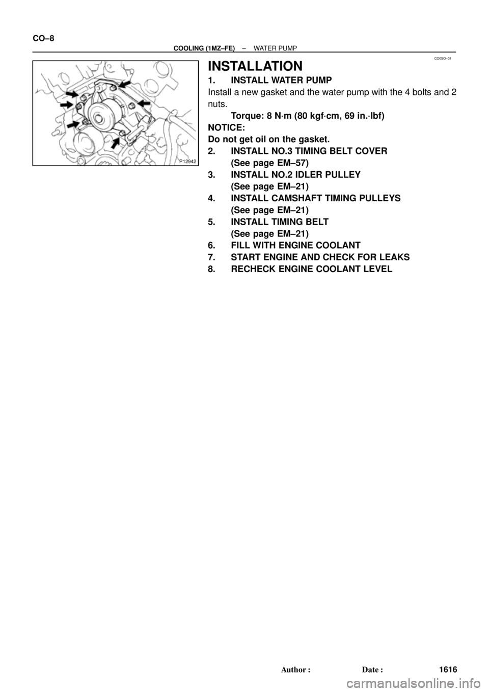
1. INSTALL WATER PUMP
Install a new gasket and the water pump with the 4 bolts and 2
nuts.
Torque: 8 N´m (80 kgf´cm, 69 in.´lbf)
NOTICE:
Do not get oil on the gasket.
2. INSTALL NO.3 TIMING BELT COVER
(See page EM±57)
3. INSTALL NO.2 IDLER PULLEY
(See page EM±21)
4. INSTALL CAMSHAFT TIMING PULLEYS
(See page EM±21)
5. INSTALL TIMING BELT
(See page EM±21)
6. FILL WITH ENGINE COOLANT
7. START ENGINE AND CHECK FOR LEAKS
8. RECHECK ENGINE COOLANT LEVEL
Page 1192 of 4592
RADIATOR
1626 Author�: Date�:
REMOVAL
HINT:
�At the time of installation, please refer to the following
items.
�Start the")
CO03O±03
S04725
B05937
Lower
Hose
Oil
Cooler
Hose
CO±18
± COOLING (1MZ±FE)RADIATOR
1626 Author�: Date�:
REMOVAL
HINT:
�At the time of installation, please refer to the following
items.
�Start the engine, and check for coolant and A/T fluid
leaks.
�Check the A/T fluid level. (See page DI±438)
1. DRAIN ENGINE COOLANT
2. CANADA:
DISCONNECT RELAY BLOCK (FOR DAYTIME
RUNNING LIGHT SYSTEM) FROM BATTERY
HOLD±DOWN CLAMP
3. DISCONNECT UPPER RADIATOR HOSE FROM
RADIATOR
4. DISCONNECT LOWER RADIATOR HOSE FROM
WATER INLET PIPE
5. DISCONNECT A/T OIL COOLER HOSES FROM OIL
COOLER PIPES
6. DISCONNECT NO.1 AND NO.2 COOLING FAN
CONNECTORS
7. DISCONNECT NO.1 ECT SWITCH WIRE CONNECTOR
8. REMOVE RADIATOR AND COOLING FANS
ASSEMBLY
(a) Remove the 2 bolts and 2 upper supports.
Torque: 12.8 N´m (130 kgf´cm, 9 ft´lbf)
(b) Lift out the radiator, and remove the radiator and cooling
fans assembly.
(c) Remove the 2 lower supports.
9. REMOVE A/T OIL COOLER HOSES FROM
RADIATOR
10. REMOVE LOWER RADIATOR HOSE FROM
RADIATOR