Page 1740 of 4592
DI±528
± DIAGNOSTICSANTI±LOCK BRAKE SYSTEM (DENSO Made)
763 Author�: Date�:
4 Check battery positive voltage.
CHECK:
Check the battery positive voltage.
OK:
10 ± 14 V
NG Check and repair the charging system
5S±FE engine: (See page CH±1)
1MZ±FE engine: (See page CH±1).
OK
5 Check ABS warning light.
PREPARATION:
(a) Disconnect the connector from the ABS ECU.
(b) Turn the ignition switch ON.
CHECK:
Check the ABS warning light goes off.
OK Check and replace ABS ECU.
NG
Check for short circuit in harness and connector between ABS warning light, DLC1, DLC2, and
ABS ECU (See page IN±31).
Page 1754 of 4592

777 Author�: Date�:
DIAGNOSTIC TROUBLE CODE CHART
HINT:
�Using SST 09843 ±18020, connect the terminals Tc and E1.
�If a malfunctio")
DI03W±11
DI±542
± DIAGNOSTICSANTI±LOCK BRAKE SYSTEM (BOSCH Made)
777 Author�: Date�:
DIAGNOSTIC TROUBLE CODE CHART
HINT:
�Using SST 09843 ±18020, connect the terminals Tc and E1.
�If a malfunction code is displayed during the DTC check, check the circuit listed for the code. For details
of each code, turn to the page referred to under the ºSee pageº for respective ºDTC No.º in the DTC
chart.
DTC No.
(See Page)Detection ItemTrouble Area
11
(DI±546)ABS solenoid valve relay faulty
�ABS solenoid valve relay
�Valve supply voltage
�ECU
13
(DI±548)ABS pump motor faulty
�ABS motor relay
�Pump motor voltage
�Pump motor lead disconnected
�ECU
21
(DI±550)Right front solenoid valves faulty�ABS actuator (right front inlet or outlet solenoid valve)
22
(DI±550)Left front solenoid valves faulty�ABS actuator (left front inlet or outlet solenoid valve)
23
(DI±550)Right rear solenoid valves faulty�ABS actuator (right rear inlet or outlet solenoid valve)
24
(DI±550)Left rear solenoid valves faulty�ABS actuator (left rear inlet or outlet solenoid valve)
31
(DI±552)Right front wheel speed sensor signal malfunction
32
(DI±552)Left front wheel speed sensor signal malfunction�Right front, left front, right rear and left rear speed sensor
�Each speed sensor circuit
33
(DI±552)Right rear wheel speed sensor signal malfunction
�Each s eed sensor circuit
�Sensor installation
�ECU
34
(DI±552)Left rear wheel speed sensor signal malfunction
35
(DI±552)Open circuit in right front wheel speed sensor circuit�Right front, left front speed sensor
Eh d i it36
(DI±552)Open circuit in left front wheel speed sensor circuit
�Each speed sensor circuit
�ECU
37
(DI±557)Speed sensor rotor is wrong number of teeth on one of the 4
wheels�Speed sensor
�Sensor rotor
�ECU
38
(DI±552)Open circuit in right rear wheel speed sensor circuit�Right rear, left rear speed sensor
Eh d i it39
(DI±552)Open circuit in left rear wheel speed sensor circuit
�Each speed sensor circuit
�ECU
41
(DI±558)Low battery positive voltage
�Battery
�Charging system regulator
�Power source circuit
�ECU
58
(DI±561)Open circuit in stop light switch circuit
�Stop light switch
�Stop light switch circuit
�ECU
62
(DI±563)Malfunction in ECU�ECU
Page 1770 of 4592

F03950
Actuator Assembly LB±R
IG1Actuator Assembly LB±R
IG1Actuator Assembly LB±R
IG1Actuator Assembly LB±R
IG1Actuator Assembly L
IG1
BatteryMAINB±G1
F4 ALTFL
Block 1F5 B±G3
ABS
12
Engine
Room R/B
No.3 3L
18
A617
A6
+B+B
Valve Relay
Motor Relay
GND2
A6
1615
A65
B±R
IK3B±R
C
C
J12 J/C
ECU
GND119
A6W±B
W±B
W±B
EAECU±IG
Instrument
Panel J/B 1J
9 DI±558
± DIAGNOSTICSANTI±LOCK BRAKE SYSTEM (BOSCH Made)
793 Author�: Date�:
DTC 41 Power Source Circuit
CIRCUIT DESCRIPTION
This is the power source for the ECU, hence the actuators.
DTC No.DTC Detecting ConditionTrouble Area
41
Vehicle speed at about 6 km/h (4 mph), low battery voltage
is less than 9.4 V at the time of non±operation of ABS
control or less than 8.8 V at the time of operation of ABS
control, and high battery voltage is more than 17.4 V.�Battery
�Charging system
�Power source circuit
�ECU
Fail safe function:
If trouble occurs in the power source circuit, the ECU cuts off current to the ABS solenoid valve relay and
prohibits ABS control.
WIRING DIAGRAM
DI045±08
Page 1771 of 4592
F00073
ECU±IG
Instrument
Panel J/BECU±IG
Instrument
Panel J/BECU±IG
Instrument
Panel J/B
± DIAGNOSTICSANTI±LOCK BRAKE SYSTEM (BOSCH Made)
DI±559
794 Author�: Date�:
INSPECTION PROCEDURE
1 Check ECU±IG fuse.
PREPARATION:
Remove ECU±IG fuse from Instrument Panel J/B.
CHECK:
Check continuity of ECU±IG fuse.
OK:
Continuity
NG Check for short circuit in all the harness and
components connected to ECU±IG fuse (See
the attached wiring diagram.)
OK
2 Check battery positive voltage.
OK:
Voltage: 10 ± 14 V
NG Check and repair the charging system
5S±FE engine: (See page CH±1)
1MZ±FE engine: (See page CH±1).
OK
Page 1790 of 4592

DI04F±04
DI±578
± DIAGNOSTICSABS & TRACTION CONTROL SYSTEM
813 Author�: Date�:
DIAGNOSTIC TROUBLE CODE CHART
HINT:
�Using SST 09843 ±18020, connect the terminals Tc and E1.
�If a malfunction code is displayed during the DTC check, check the circuit listed for the code. For details
of each code, turn to the page referred to under the ºSee pageº for respective ºDTC No.º in the DTC
chart.
DTC No.
(See Page)Detection ItemTrouble Area
11
(DI±584)Open circuit in ABS & TRAC solenoid relay circuit�ABS & TRAC solenoid relay
ABS & TRAC l id l i it12
(DI±584)Short circuit in ABS & TRAC solenoid relay circuit
�ABS & TRAC solenoid relay circuit
�ECU
13
(DI±587)Open circuit in ABS & TRAC motor relay circuit�ABS & TRAC motor relay
ABS & TRAC t l i it14
(DI±587)Short circuit in ABS & TRAC motor relay circuit
�ABS & TRAC motor relay circuit
�ECU
21
(DI±590)Open or short circuit in right front solenoid circuit
�ABS & TRAC actuator
�SFRR or SFRH circuit
�ECU
22
(DI±590)Open or short circuit in left front solenoid circuit
�ABS & TRAC actuator
�SFLR or SFLH circuit
�ECU
23
(DI±590)Open or short circuit in right rear solenoid circuit
�ABS & TRAC actuator
�SRRR or SRRH circuit
�ECU
24
(DI±590)Open or short circuit in left rear solenoid circuit
�ABS & TRAC actuator
�SRLR or SRLH circuit
�ECU
25
(DI±590)Open or short circuit in SMC1 circuit
�ABS & TRAC actuator
�SMC1 circuit
�ECU
26
(DI±590)Open or short circuit in SMC2 circuit
�ABS & TRAC actuator
�SMC2 circuit
�ECU
27
(DI±590)Open or short circuit in SRC1 circuit
�ABS & TRAC actuator
�SRC1 circuit
�ECU
28
(DI±590)Open or short circuit in SRC2 circuit
�ABS & TRAC actuator
�SRC2 circuit
�ECU
31
(DI±593)Right front wheel speed sensor signal malfunction
32
(DI±593)Left front wheel speed sensor signal malfunction�Right front, left front, right rear and left rear speed sensor
�Each speed sensor circuit
33
(DI±593)Right rear wheel speed sensor signal malfunction
�Each s eed sensor circuit
�Speed sensor rotor
�ECU
34
(DI±593)Left rear wheel speed sensor signal malfunction
41
(DI±598)Low battery positive voltage or abnormally high battery
positive voltage
�Battery
�Charging system
�Power source circuit
�ECU
Page 1810 of 4592

F00175
Battery MAIN FL Block
B±G 1K2Ignition
Switch
Instrument Panel J/B
1B
F4 F91A16
GND3
B±R
1Instrument Panel J/B
1
A15 B±YJ/C
4B±R
CABS & TRAC ECU
9
A17 1JJ12
IG1
W±B W
GND1
GND2 21K1
CB±R
A17 W±B
W±B
EA8
15
109
W±B
W±B
Battery MAIN FL Block
B±G 1K2Ignition
Switch
Instrument Panel J/B
1B
F4 F91A16
GND3
B±R
1Instrument Panel J/B
1
A15 B±YJ/C
4B±R
CABS & TRAC ECU
9
A17 1JJ12
IG1
W±B W
GND1
GND2 21K1
CB±R
A17 W±B
W±B
EA8
15
109
W±B
W±B
Battery MAIN FL Block
B±G 1K2Ignition
Switch
Instrument Panel J/B
1B
F4 F91A16
GND3
B±R
1Instrument Panel J/B
1
A15 B±YJ/C
4B±R
CABS & TRAC ECU
9
A17 1JJ12
IG1
W±B W
GND1
GND2 21K1
CB±R
A17 W±B
W±B
EA8
15
109
W±B
W±B
Battery MAIN FL Block
B±G 1K2Ignition
Switch
Instrument Panel J/B
1B
F4 F91A16
GND3
B±R
1Instrument Panel J/B
1
A15 B±YJ/C
4B±R
CABS & TRAC ECU
9
A17 1JJ12
IG1
W±B W
GND1
GND2 21K1
CB±R
A17 W±B
W±B
EA8
15
109
W±B
W±BBattery MAIN FL Block
ALT
B±GAM1 1K2Ignition
Switch
Instrument Panel J/B
1B
F4 F91A16
GND3
B±R
1Instrument Panel J/B
1
A15 B±YJ/C
ECU±IG 4B±R
CABS & TRAC ECU
9
A17 1JJ12
IG1
W±B W
GND1
GND2 21K1
CB±R
A17 W±B
W±B
EA8
15
109
W±B
W±B DI±598
± DIAGNOSTICSABS & TRACTION CONTROL SYSTEM
833 Author�: Date�:
DTC 41 IG Power Source Circuit
CIRCUIT DESCRIPTION
This is the power source for the ECU, hence the actuators.
DTC No.DTC Detecting ConditionTrouble Area
41
Detection of any conditions from 1. through 3.:
1. Vehicle speed is 3 km/h (1.9 mph) or more and battery
voltage is less than 9.5 V continues for 10 sec. or more.
2. Battery voltage has never exceeded more than 17.0 V
and has become less than 9.5 V within 2.16 sec., under
malfunction of solenoid relay monitor after the solenoid
relay is ON, at ECU AST terminal voltage of ECU has
become 8.0 V or more or under malfunction of motor
relay monitor and after the motor relay is ON, motor
relay monitor has become ON.
3. Battery voltage is more than 17.0 V , which continues for
1.2 sec. or more or battery voltage has become more
than 17.0 V within 2.16 sec. and solenoid or motor relay
monitor is under malfunction condition.
�Battery
�Charging system
�Power source circuit
�ECU
Fail safe function:
If any trouble occurs in the power source circuit, the ECU cuts off current to the ABS & TRAC solenoid relay
and prohibits ABS control and TRAC control.
WIRING DIAGRAM
DI04N±04
Page 1811 of 4592
F00073
ECU±IGECU±IG
Instrument
Panel J/BECU±IG
± DIAGNOSTICSABS & TRACTION CONTROL SYSTEM
DI±599
834 Author�: Date�:
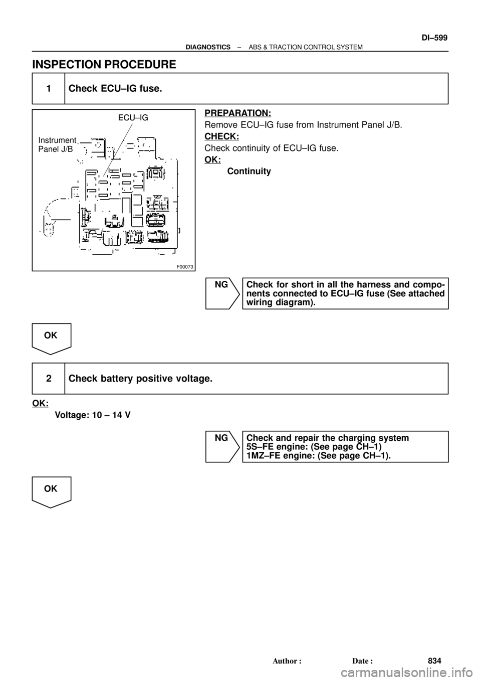
INSPECTION PROCEDURE
1 Check ECU±IG fuse.
PREPARATION:
Remove ECU±IG fuse from Instrument Panel J/B.
CHECK:
Check continuity of ECU±IG fuse.
OK:
Continuity
NG Check for short in all the harness and compo-
nents connected to ECU±IG fuse (See attached
wiring diagram).
OK
2 Check battery positive voltage.
OK:
Voltage: 10 ± 14 V
NG Check and repair the charging system
5S±FE engine: (See page CH±1)
1MZ±FE engine: (See page CH±1).
OK
Page 1823 of 4592
± DIAGNOSTICSABS & TRACTION CONTROL SYSTEM
DI±611
846 Author�: Date�:
4 Check battery positive voltage.
CHECK:
Check the battery positive voltage.
OK:
10 ± 14 V
NG Check and repair the charging system
5S±FE engine: (See page CH±1)
1MZ±FE engine: (See page CH±1).
OK
5 Check ABS warning light.
PREPARATION:
(a) Disconnect the connector from the ABS & TRAC ECU.
(b) Turn the ignition switch ON.
CHECK:
Check the ABS warning light goes off.
OK Check and replace ABS & TRAC ECU.
NG
Check for short circuit in harness and connector between ABS warning light, DLC1, DLC2, and
ABS & TRAC ECU (See page IN±31)