Page 1090 of 4592
P14433
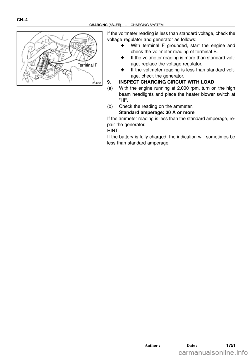
Terminal F CH±4
± CHARGING (5S±FE)CHARGING SYSTEM
1751 Author�: Date�:
If the voltmeter reading is less than standard voltage, check the
voltage regulator and generator as follows:
�With terminal F grounded, start the engine and
check the voltmeter reading of terminal B.
�If the voltmeter reading is more than standard volt-
age, replace the voltage regulator.
�If the voltmeter reading is less than standard volt-
age, check the generator.
9. INSPECT CHARGING CIRCUIT WITH LOAD
(a) With the engine running at 2,000 rpm, turn on the high
beam headlights and place the heater blower switch at
ºHIº.
(b) Check the reading on the ammeter.
Standard amperage: 30 A or more
If the ammeter reading is less than the standard amperage, re-
pair the generator.
HINT:
If the battery is fully charged, the indication will sometimes be
less than standard amperage.
Page 1091 of 4592
CH02V±03
S05342
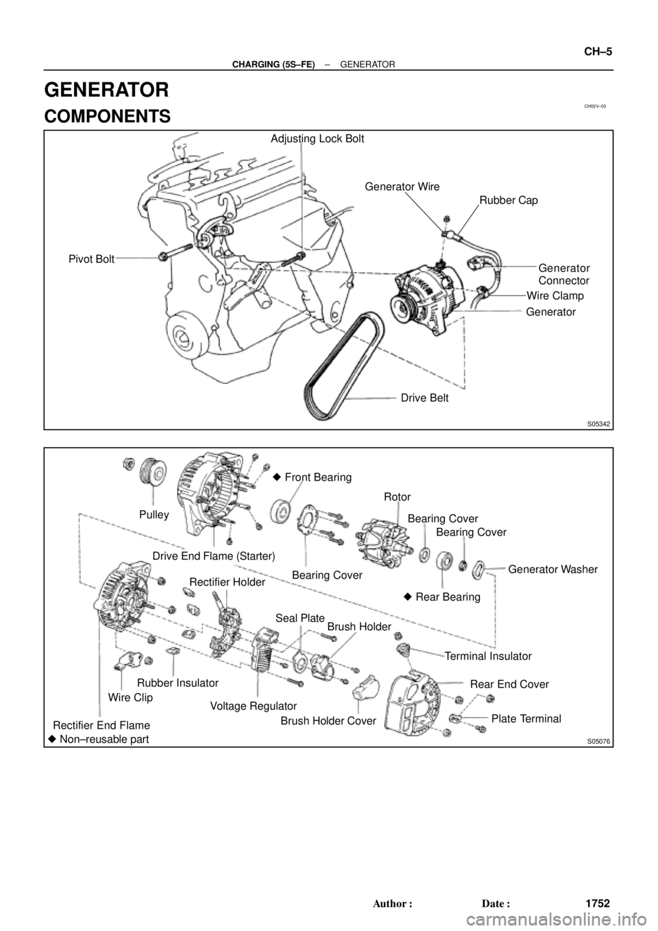
Pivot BoltAdjusting Lock Bolt
Generator Wire
Generator
Connector
Generator
Drive Belt
Rubber Cap
Wire Clamp
S05076
Pulley
Drive End Flame (Starter)� Front Bearing
Bearing CoverRotor
Generator Washer
Rectifier End FlameWire ClipRubber InsulatorRectifier Holder
Voltage RegulatorSeal Plate
Brush Holder
Brush Holder CoverTerminal Insulator
Rear End Cover
Plate Terminal
� Non±reusable partBearing Cover
� Rear BearingBearing Cover
± CHARGING (5S±FE)GENERATOR
CH±5
1752 Author�: Date�:
GENERATOR
COMPONENTS
Page 1092 of 4592
CH02W±03
B02375
B02376B02377B02693
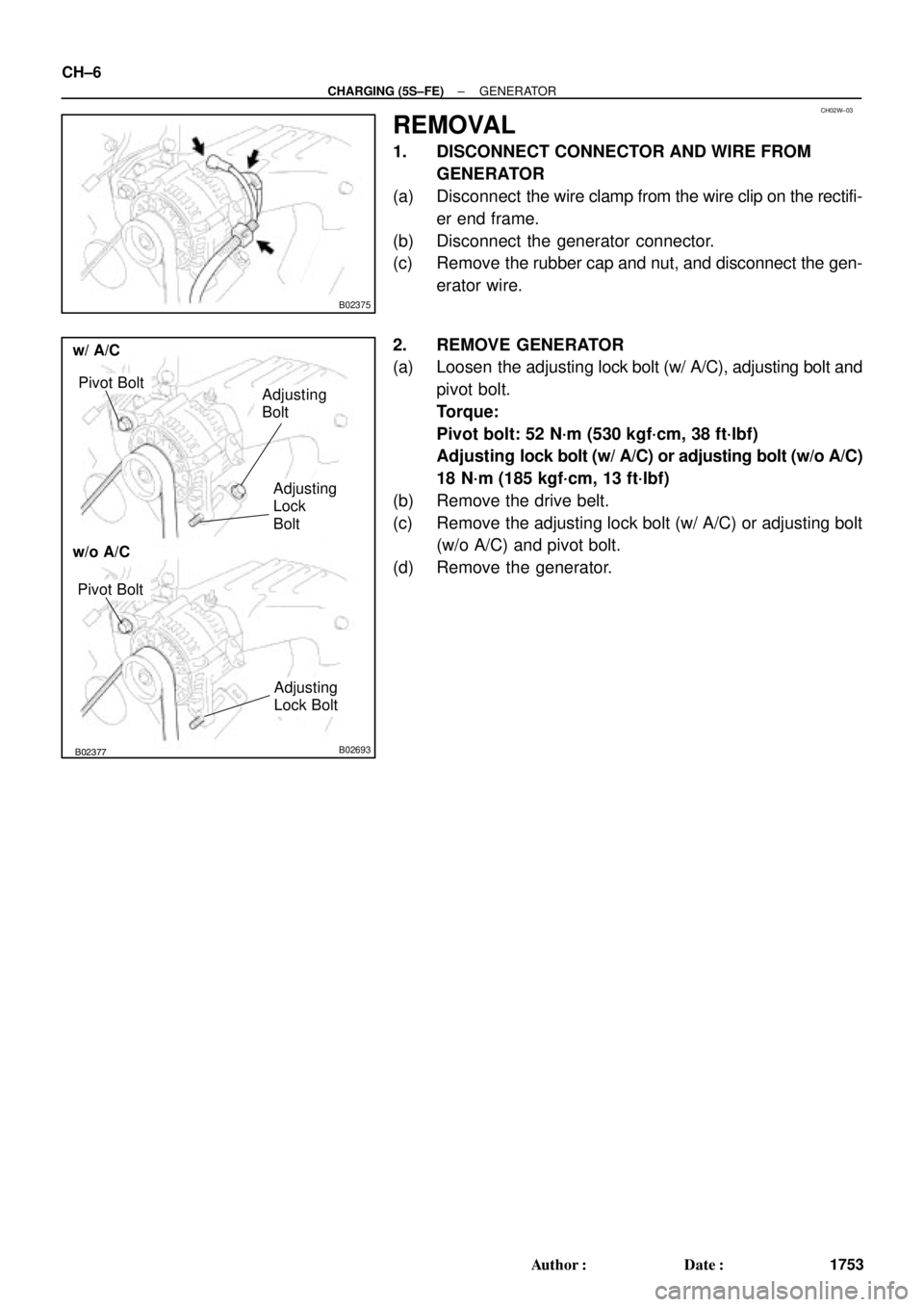
w/o A/C
w/ A/C
Pivot BoltAdjusting
Bolt
Adjusting
Lock
Bolt
Pivot Bolt
Adjusting
Lock Bolt
CH±6
± CHARGING (5S±FE)GENERATOR
1753 Author�: Date�:
REMOVAL
1. DISCONNECT CONNECTOR AND WIRE FROM
GENERATOR
(a) Disconnect the wire clamp from the wire clip on the rectifi-
er end frame.
(b) Disconnect the generator connector.
(c) Remove the rubber cap and nut, and disconnect the gen-
erator wire.
2. REMOVE GENERATOR
(a) Loosen the adjusting lock bolt (w/ A/C), adjusting bolt and
pivot bolt.
Torque:
Pivot bolt: 52 N´m (530 kgf´cm, 38 ft´lbf)
Adjusting lock bolt (w/ A/C) or adjusting bolt (w/o A/C)
18 N´m (185 kgf´cm, 13 ft´lbf)
(b) Remove the drive belt.
(c) Remove the adjusting lock bolt (w/ A/C) or adjusting bolt
(w/o A/C) and pivot bolt.
(d) Remove the generator.
Page 1093 of 4592
CH02X±01
Z18635
Z18636
B02378
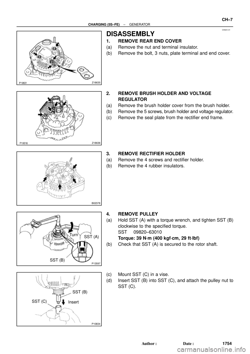
P13597SST (B)
SST (A) Turn
P10834
SST (B)
SST (C)
Insert
± CHARGING (5S±FE)GENERATOR
CH±7
1754 Author�: Date�:
DISASSEMBLY
1. REMOVE REAR END COVER
(a) Remove the nut and terminal insulator.
(b) Remove the bolt, 3 nuts, plate terminal and end cover.
2. REMOVE BRUSH HOLDER AND VOLTAGE
REGULATOR
(a) Remove the brush holder cover from the brush holder.
(b) Remove the 5 screws, brush holder and voltage regulator.
(c) Remove the seal plate from the rectifier end frame.
3. REMOVE RECTIFIER HOLDER
(a) Remove the 4 screws and rectifier holder.
(b) Remove the 4 rubber insulators.
4. REMOVE PULLEY
(a) Hold SST (A) with a torque wrench, and tighten SST (B)
clockwise to the specified torque.
SST 09820±63010
Torque: 39 N´m (400 kgf´cm, 29 ft´lbf)
(b) Check that SST (A) is secured to the rotor shaft.
(c) Mount SST (C) in a vise.
(d) Insert SST (B) into SST (C), and attach the pulley nut to
SST (C).
Page 1094 of 4592
P10827
SST (C)
SST (A)
Turn
P13598SST (B)
SST (A) Turn
S05070
P13490
SST CH±8
± CHARGING (5S±FE)GENERATOR
1755 Author�: Date�:
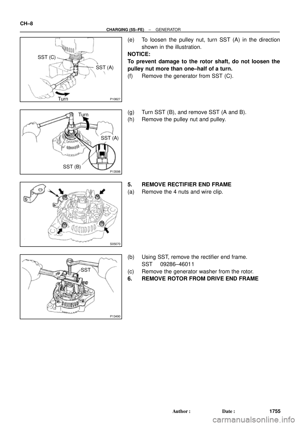
(e) To loosen the pulley nut, turn SST (A) in the direction
shown in the illustration.
NOTICE:
To prevent damage to the rotor shaft, do not loosen the
pulley nut more than one±half of a turn.
(f) Remove the generator from SST (C).
(g) Turn SST (B), and remove SST (A and B).
(h) Remove the pulley nut and pulley.
5. REMOVE RECTIFIER END FRAME
(a) Remove the 4 nuts and wire clip.
(b) Using SST, remove the rectifier end frame.
SST 09286±46011
(c) Remove the generator washer from the rotor.
6. REMOVE ROTOR FROM DRIVE END FRAME
Page 1095 of 4592
GENERATOR
CH±9
1756 Author�: Date�:
INSPECTION
1")
CH02Y±01
CH0784
Ohmmeter
Continuity
CH0783
Ohmmeter
No Continuity
CH1023
P13482
Ohmmeter
Continuity
P13565
Ohmmeter
No Continuity
± CHARGING (5S±FE)GENERATOR
CH±9
1756 Author�: Date�:
INSPECTION
1. INSPECT ROTOR
(a) Check the rotor for open circuit.
Using an ohmmeter, check that there is continuity be-
tween the slip rings.
Standard resistance: 2.7 ± 3.1 W at 20°C (68°F)
If there is no continuity, replace the rotor.
(b) Check the rotor for ground.
Using an ohmmeter, check that there is no continuity be-
tween the slip ring and rotor.
If there is continuity, replace the rotor.
(c) Check that the slip rings are not rough or scored.
If rough or scored, replace the rotor.
(d) Using vernier calipers, measure the slip ring diameter.
Standard diameter: 14.2 ± 14.4 mm (0.559 ± 0.567 in.)
Minimum diameter: 12.8 mm (0.504 in.)
If the diameter is less than minimum, replace the rotor.
2. INSPECT STATOR (DRIVE END FRAME)
(a) Check the stator for open circuit.
Using an ohmmeter, check that there is continuity be-
tween the coil leads.
If there is no continuity, replace the drive end frame assembly.
(b) Check the stator for ground.
Using an ohmmeter, check that there is no continuity be-
tween the coil lead and drive end frame.
If there is continuity, replace the drive end frame assembly.
Page 1096 of 4592

Terminal
Rectifier
Terminal
P13566
Ohmmeter
Negative (±)
Terminal
CH±10
± CHARGING (5S±FE)GENERATOR
1757 Author�: Date�:
3. INSPECT BRUSHES
Using vernier")
P13535
Length
P13568
Ohmmeter
Positive (+)
Terminal
Rectifier
Terminal
P13566
Ohmmeter
Negative (±)
Terminal
CH±10
± CHARGING (5S±FE)GENERATOR
1757 Author�: Date�:
3. INSPECT BRUSHES
Using vernier calipers, measure the exposed brush length.
Standard exposed length: 10.5 mm (0.413 in.)
Minimum exposed length: 1.5 mm (0.059 in.)
If the exposed length is less than minimum, replace the brush
holder assembly.
4. INSPECT RECTIFIERS (RECTIFIRE HOLDER)
(a) Check the positive (+) rectifire.
(1) Using an ohmmeter, connect one tester probe to the
positive (+) terminal and the other to each rectifier
terminal.
(2) Reverse the polarity of the tester probes and repeat
step (a).
(3) Check that one shows continuity and the other
shows no continuity.
If continuity is not as specified, replace the rectifier holder.
(b) Check the negative (±) rectifire.
(1) Using an ohmmeter, connect one tester probe to
each negative (±) terminal and the other to each
rectifier terminal.
(2) Reverse the polarity of the tester probes and repeat
step (a).
(3) Check that one shows continuity and the other
shows no continuity.
If continuity is not as specified, replace the rectifier holder.
5. INSPECT BEARING
Check the bearing is not rough or worn.
If necessary, replace the bearing. (See page CH±11)
Page 1097 of 4592
CH02Z±01
CH0827
P00100
Socket Wrench
P13479
Downward SST
N00581
SST
P13567
± CHARGING (5S±FE)GENERATOR
CH±11
1758 Author�: Date�:
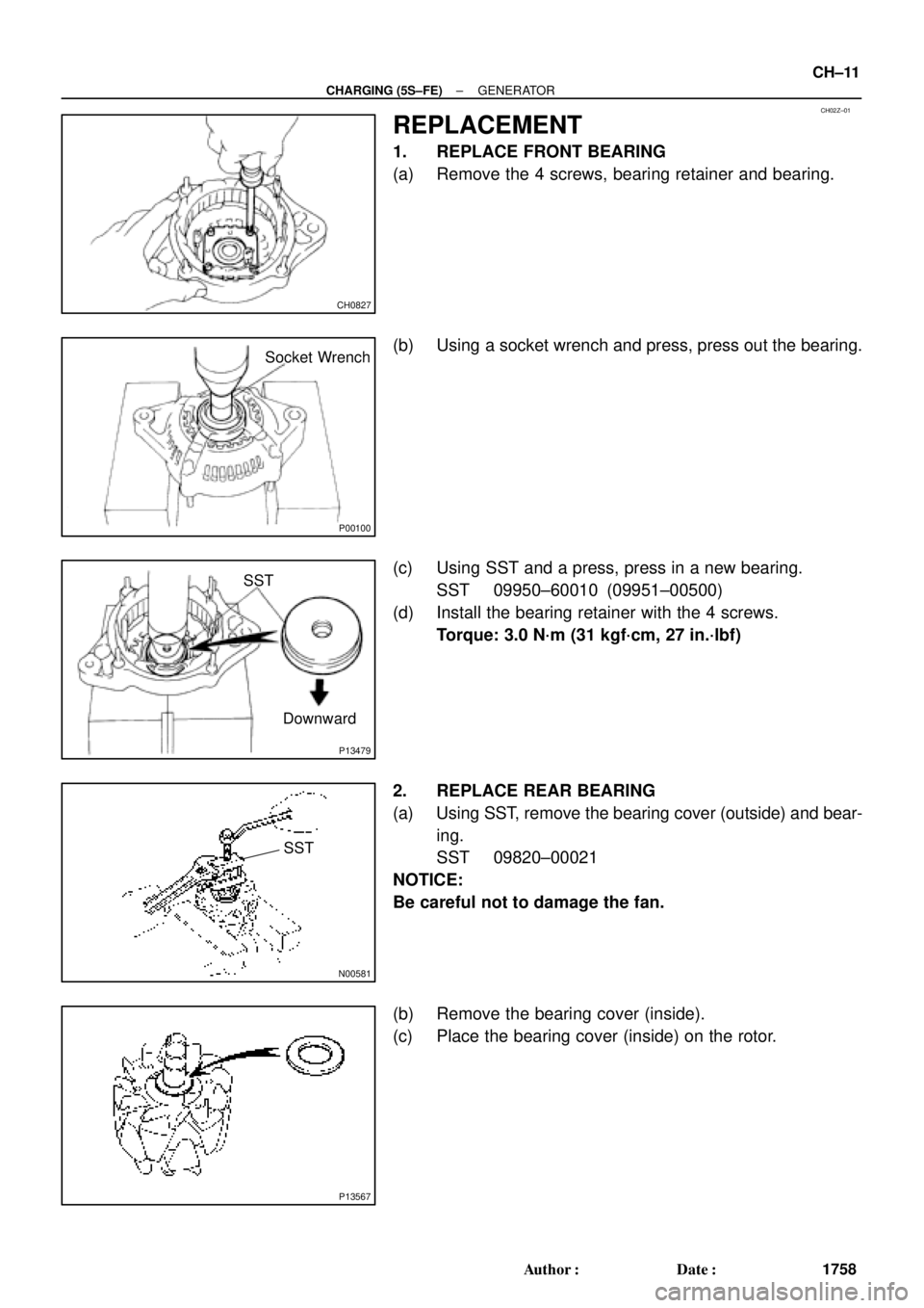
REPLACEMENT
1. REPLACE FRONT BEARING
(a) Remove the 4 screws, bearing retainer and bearing.
(b) Using a socket wrench and press, press out the bearing.
(c) Using SST and a press, press in a new bearing.
SST 09950±60010 (09951±00500)
(d) Install the bearing retainer with the 4 screws.
Torque: 3.0 N´m (31 kgf´cm, 27 in.´lbf)
2. REPLACE REAR BEARING
(a) Using SST, remove the bearing cover (outside) and bear-
ing.
SST 09820±00021
NOTICE:
Be careful not to damage the fan.
(b) Remove the bearing cover (inside).
(c) Place the bearing cover (inside) on the rotor.