Page 1114 of 4592
N00578
SST
P00074
SST
CH±12
± CHARGING (1MZ±FE)GENERATOR
1775 Author�: Date�:
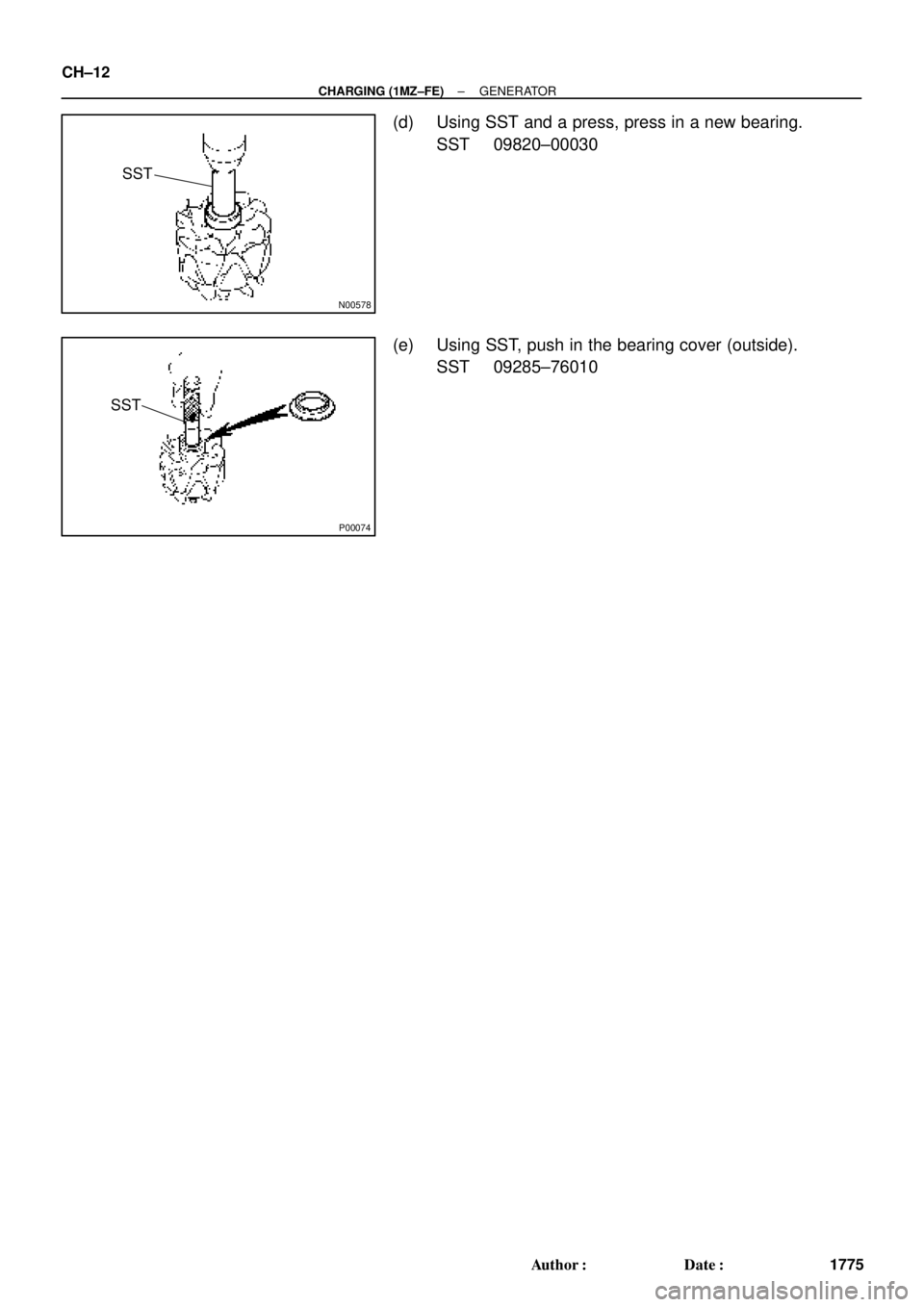
(d) Using SST and a press, press in a new bearing.
SST 09820±00030
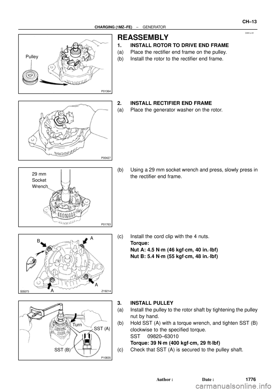
(e) Using SST, push in the bearing cover (outside).
SST 09285±76010
Page 1115 of 4592
CH01J±01
P01364
Pulley
P00427
P01763
29 mm
Socket
Wrench
Z19214AA A
B
P10835
Turn
SST (A)
SST (B)
± CHARGING (1MZ±FE)GENERATOR
CH±13
1776 Author�: Date�:
REASSEMBLY
1. INSTALL ROTOR TO DRIVE END FRAME
(a) Place the rectifier end frame on the pulley.
(b) Install the rotor to the rectifier end frame.
2. INSTALL RECTIFIER END FRAME
(a) Place the generator washer on the rotor.
(b) Using a 29 mm socket wrench and press, slowly press in
the rectifier end frame.
(c) Install the cord clip with the 4 nuts.
Torque:
Nut A: 4.5 N´m (46 kgf´cm, 40 in.´lbf)
Nut B: 5.4 N´m (55 kgf´cm, 48 in.´lbf)
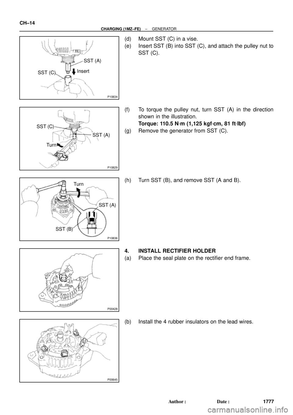
3. INSTALL PULLEY
(a) Install the pulley to the rotor shaft by tightening the pulley
nut by hand.
(b) Hold SST (A) with a torque wrench, and tighten SST (B)
clockwise to the specified torque.
SST 09820±63010
Torque: 39 N´m (400 kgf´cm, 29 ft´lbf)
(c) Check that SST (A) is secured to the pulley shaft.
Page 1116 of 4592
P10834
SST (C)SST (A)
Insert
P10829
SST (C)
SST (A)
Turn
P10836
SST (B)SST (A) Turn
P00428
P00645
CH±14
± CHARGING (1MZ±FE)GENERATOR
1777 Author�: Date�:
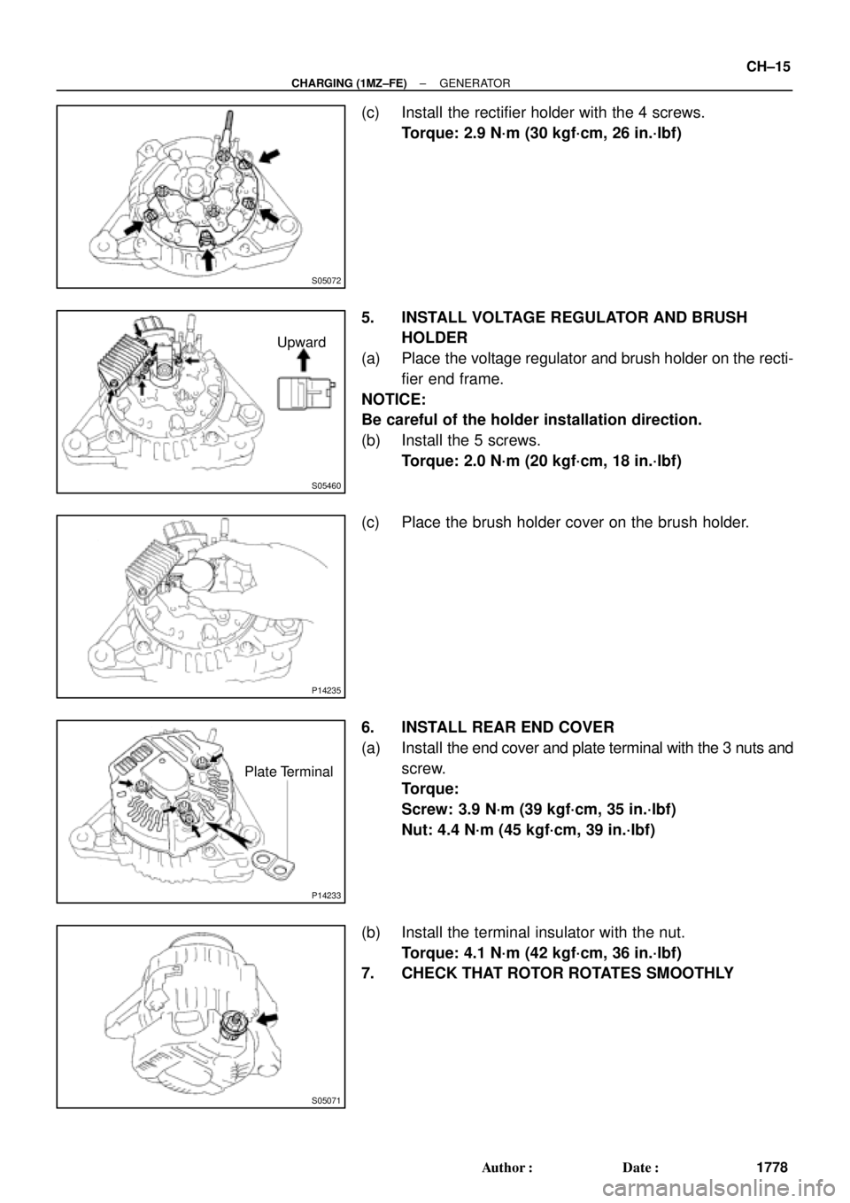
(d) Mount SST (C) in a vise.
(e) Insert SST (B) into SST (C), and attach the pulley nut to
SST (C).
(f) To torque the pulley nut, turn SST (A) in the direction
shown in the illustration.
Torque: 110.5 N´m (1,125 kgf´cm, 81 ft´lbf)
(g) Remove the generator from SST (C).
(h) Turn SST (B), and remove SST (A and B).
4. INSTALL RECTIFIER HOLDER
(a) Place the seal plate on the rectifier end frame.
(b) Install the 4 rubber insulators on the lead wires.
Page 1117 of 4592
S05072
S05460
Upward
P14235
P14233
Plate Terminal
S05071
± CHARGING (1MZ±FE)GENERATOR
CH±15
1778 Author�: Date�:
(c) Install the rectifier holder with the 4 screws.
Torque: 2.9 N´m (30 kgf´cm, 26 in.´lbf)
5. INSTALL VOLTAGE REGULATOR AND BRUSH
HOLDER
(a) Place the voltage regulator and brush holder on the recti-
fier end frame.
NOTICE:
Be careful of the holder installation direction.
(b) Install the 5 screws.
Torque: 2.0 N´m (20 kgf´cm, 18 in.´lbf)
(c) Place the brush holder cover on the brush holder.
6. INSTALL REAR END COVER
(a) Install the end cover and plate terminal with the 3 nuts and
screw.
Torque:
Screw: 3.9 N´m (39 kgf´cm, 35 in.´lbf)
Nut: 4.4 N´m (45 kgf´cm, 39 in.´lbf)
(b) Install the terminal insulator with the nut.
Torque: 4.1 N´m (42 kgf´cm, 36 in.´lbf)
7. CHECK THAT ROTOR ROTATES SMOOTHLY
Page 1118 of 4592
CH01K±01
CH±16
± CHARGING (1MZ±FE)GENERATOR
1779 Author�: Date�:
INSTALLATION
Installation is in the reverse order of removal. (See page ST±5)
Page 1709 of 4592

DI±497
732 Author�: Date�:
DIAGNOSTIC TROUBLE CODE CHART
HINT:
�Using SST 09843 ±18020, connect the terminals Tc and E1, and remove the s")
DI03D±03
± DIAGNOSTICSANTI±LOCK BRAKE SYSTEM (DENSO Made)
DI±497
732 Author�: Date�:
DIAGNOSTIC TROUBLE CODE CHART
HINT:
�Using SST 09843 ±18020, connect the terminals Tc and E1, and remove the short pin.
�If any abnormality is not found when inspection parts, inspect the ECU.
�If a malfunction code is displayed during the DTC check, check the circuit listed for the code. For details
of each code, turn to the page referred to under the ºSee pageº for respective ºDTC No.º in the DTC
chart.
DTC No.
(See Page)Detection ItemTrouble Area
11
(DI±502)Open circuit in ABS solenoid relay circuit�ABS solenoid relay
12
(DI±502)Short circuit in ABS solenoid relay circuit
�ABS solenoid relay
�ABS solenoid relay circuit
13
(DI±507)Open circuit in ABS motor relay circuit�ABS motor relay
14
(DI±507)Short circuit in ABS motor relay circuit
�ABS motor relay
�ABS motor relay circuit
21
(DI±511)Open or short circuit in 2±position solenoid circuit for right front
wheel�ABS actuator
�SFRR or SFRH circuit
22
(DI±511)Open or short circuit in 2±position solenoid circuit for left front
wheel�ABS actuator
�SFLR or SFLH circuit
23
(DI±511)Open or short circuit in 2±position solenoid circuit for right rear
wheel�ABS actuator
�SRRR or SRRH circuit
24
(DI±511)Open or short circuit in 2±position solenoid circuit for left rear
wheel�ABS actuator
�SRLR or SRLH circuit
31
(DI±514)Right front wheel speed sensor signal malfunction
32
(DI±514)Left front wheel speed sensor signal malfunction�Right front, left front, right rear and left rear speed sensor
Eh d i it33
(DI±514)Right rear wheel speed sensor signal malfunction
�Each speed sensor circuit
�Speed sensor rotor
34
(DI±514)Left rear wheel speed sensor signal malfunction
33, 34
(DI±519)Rear speed sensor rotor faulty
�Rear axle hub
�Right rear, left rear speed sensor
�Rear speed sensor circuit
41
(DI±520)Power source voltage down
�Battery
�Charging system
�Power source circuit
49
(DI±523)Open circuit in stop light switch circuit�Stop light switch
�Stop light switch circuit
51
(DI±525)Pump motor is locked�ABS pump motor
Always ON
(DI±527)Malfunction in ECU�ECU
�Battery
Page 1732 of 4592

F07156
Ignition
Switch
W24
AM1
IG1
B±YInstrument Panel J/B
19
1K
ECU±IG1JB±RJ/C
J12
C
CB±R13
A19ABS ECU
IG1
Instrument Panel J/B
21
1K
1B
AM1
B±R
FL Block
1
1
F4 F9
ALT
B±G
FL MAIN
Battery
IG A
Instrument
Panel Brace LH J11
Junction
ConnectorW±B
W±B12
A19
A1925GND1
GND2 DI±520
± DIAGNOSTICSANTI±LOCK BRAKE SYSTEM (DENSO Made)
755 Author�: Date�:
DTC 41 IG Power Source Circuit
CIRCUIT DESCRIPTION
This is the power source for the ECU, hence the actuators.
DTC No.DTC Detecting ConditionTrouble Area
41
Condition 1. or 2. is detected:
1. Vehicle speed is at 3 km/h (1.9 mph) or more and ECU
terminal IG1 voltage is 9.5 V or less , which continues
for 10 sec. or more.
2. When IG1 terminal voltage is less than 9.5 V, there is
open circuit in the motor relay or in the solenoid relay, or
the solenoid circuit malfunction.
�Battery
�Charging system
�Power source circuit
Fail safe function:
If trouble occurs in the power source circuit, the ECU cuts off current to the ABS solenoid relay and prohibits
ABS control.
WIRING DIAGRAM
DI03M±03
Page 1733 of 4592
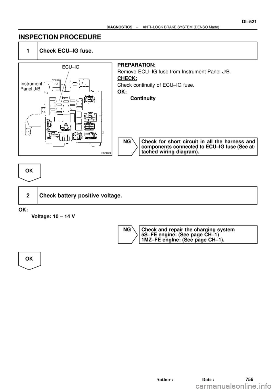
F00073
ECU±IGECU±IG
Instrument
Panel J/BECU±IG
± DIAGNOSTICSANTI±LOCK BRAKE SYSTEM (DENSO Made)
DI±521
756 Author�: Date�:
INSPECTION PROCEDURE
1 Check ECU±IG fuse.
PREPARATION:
Remove ECU±IG fuse from Instrument Panel J/B.
CHECK:
Check continuity of ECU±IG fuse.
OK:
Continuity
NG Check for short circuit in all the harness and
components connected to ECU±IG fuse (See at-
tached wiring diagram).
OK
2 Check battery positive voltage.
OK:
Voltage: 10 ± 14 V
NG Check and repair the charging system
5S±FE engine: (See page CH±1)
1MZ±FE engIne: (See page CH±1).
OK