Page 1968 of 4592
AB0119H01298H01299
(±) (+)ONAirbag Sensor Assembly
ACC
IG2
DI±756
± DIAGNOSTICSSUPPLEMENTAL RESTRAINT SYSTEM
991 Author�: Date�:
DTC B1100/31 Airbag Sensor Assembly Malfunction
CIRCUIT DESCRIPTION
The airbag sensor assembly consists of a airbag sensor, safing sensor, drive circuit, diagnosis circuit and
ignition control, etc.
It receives signals from the airbag sensor, judges whether or not the SRS must be activated, and detects
diagnosis system malfunction.
DTC B1100/31 is recorded when occurrence of a malfunction in the airbag sensor assembly is detected.
DTC No.DTC Detecting ConditionTrouble Area
B1100/31�Airbag sensor assembly malfunction�Airbag sensor assembly
INSPECTION PROCEDURE
HINT:
When a malfunction code other than code B1100/31 is displayed at the same time, first repair the malfunction
indicated by the malfunction code other than code B1100/31.
1 Prepare for inspection. (See step 1 on page DI±787)
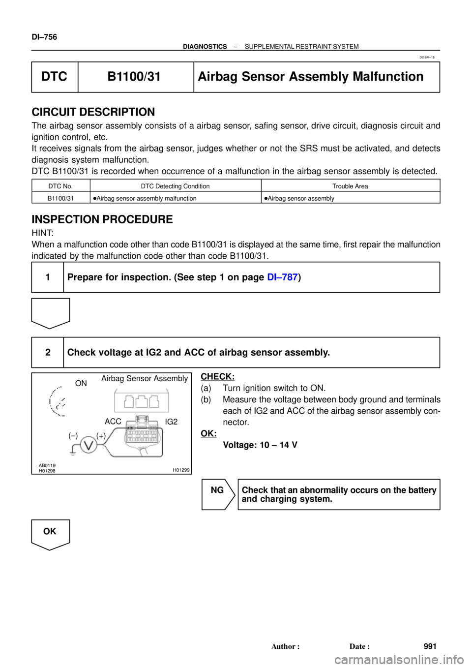
2 Check voltage at IG2 and ACC of airbag sensor assembly.
CHECK:
(a) Turn ignition switch to ON.
(b) Measure the voltage between body ground and terminals
each of IG2 and ACC of the airbag sensor assembly con-
nector.
OK:
Voltage: 10 ± 14 V
NG Check that an abnormality occurs on the battery
and charging system.
OK
DI1BM±18
Page 2001 of 4592
AB0119H01298H01299
Airbag Sensor Assembly
ON
ACC
IG2
(+) (±)
H01249
ON
± DIAGNOSTICSSUPPLEMENTAL RESTRAINT SYSTEM
DI±789
1024 Author�: Date�:
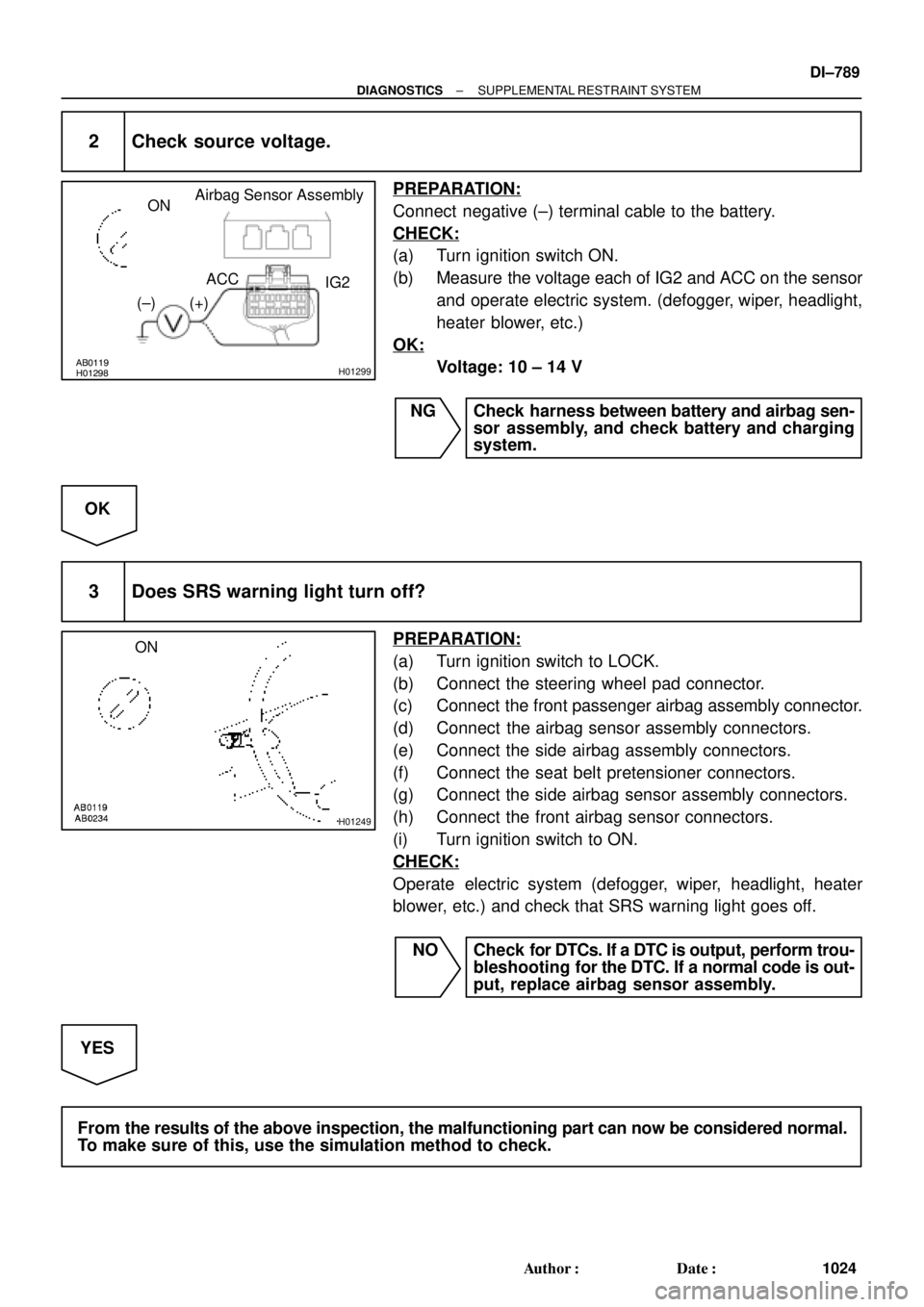
2 Check source voltage.
PREPARATION:
Connect negative (±) terminal cable to the battery.
CHECK:
(a) Turn ignition switch ON.
(b) Measure the voltage each of IG2 and ACC on the sensor
and operate electric system. (defogger, wiper, headlight,
heater blower, etc.)
OK:
Voltage: 10 ± 14 V
NG Check harness between battery and airbag sen-
sor assembly, and check battery and charging
system.
OK
3 Does SRS warning light turn off?
PREPARATION:
(a) Turn ignition switch to LOCK.
(b) Connect the steering wheel pad connector.
(c) Connect the front passenger airbag assembly connector.
(d) Connect the airbag sensor assembly connectors.
(e) Connect the side airbag assembly connectors.
(f) Connect the seat belt pretensioner connectors.
(g) Connect the side airbag sensor assembly connectors.
(h) Connect the front airbag sensor connectors.
(i) Turn ignition switch to ON.
CHECK:
Operate electric system (defogger, wiper, headlight, heater
blower, etc.) and check that SRS warning light goes off.
NO Check for DTCs. If a DTC is output, perform trou-
bleshooting for the DTC. If a normal code is out-
put, replace airbag sensor assembly.
YES
From the results of the above inspection, the malfunctioning part can now be considered normal.
To make sure of this, use the simulation method to check.
Page 2333 of 4592

DI03D±04
± DIAGNOSTICSANTI±LOCK BRAKE SYSTEM
DI±181
DIAGNOSTIC TROUBLE CODE CHART
HINT:
�Using SST 09843 ±18020, connect the terminals Tc and E1, and remove the short pin.
�If any abnormality is not found when inspection parts, inspect the ECU.
�If a malfunction code is displayed during the DTC check, check the circuit listed for the code. For details
of each code, turn to the page referred to under the ºSee pageº for respective ºDTC No.º in the DTC
chart.
DTC No.
(See Page)Detection ItemTrouble Area
11
(DI±186)Open circuit in ABS solenoid relay circuit�ABS solenoid relay
12
(DI±186)Short circuit in ABS solenoid relay circuit
�ABS solenoid relay
�ABS solenoid relay circuit
13
(DI±191)Open circuit in ABS motor relay circuit�ABS motor relay
14
(DI±191)Short circuit in ABS motor relay circuit
�ABS motor relay
�ABS motor relay circuit
21
(DI±195)Open or short circuit in 2±position solenoid circuit for right front
wheel�ABS actuator
�SFRR or SFRH circuit
22
(DI±195)Open or short circuit in 2±position solenoid circuit for left front
wheel�ABS actuator
�SFLR or SFLH circuit
23
(DI±195)Open or short circuit in 2±position solenoid circuit for right rear
wheel�ABS actuator
�SRRR or SRRH circuit
24
(DI±195)Open or short circuit in 2±position solenoid circuit for left rear
wheel�ABS actuator
�SRLR or SRLH circuit
31
(DI±198)Right front wheel speed sensor signal malfunction
32
(DI±198)Left front wheel speed sensor signal malfunction�Right front, left front, right rear and left rear speed sensor
Eh d i it33
(DI±198)Right rear wheel speed sensor signal malfunction
�Each speed sensor circuit
�Speed sensor rotor
34
(DI±198)Left rear wheel speed sensor signal malfunction
33, 34
(DI±203)Rear speed sensor rotor faulty
�Rear axle hub
�Right rear, left rear speed sensor
�Rear speed sensor circuit
41
(DI±204)Power source voltage down
�Battery
�Charging system
�Power source circuit
49
(DI±207)Open circuit in stop light switch circuit�Stop light switch
�Stop light switch circuit
51
(DI±209)Pump motor is locked�ABS pump motor
Always ON
(DI±211)Malfunction in ECU�ECU
�Battery
Page 2356 of 4592
F07156
Ignition
Switch
W24
AM1
IG1
B±YInstrument Panel J/B
19
1K
ECU±IG1JB±RJ/C
J12
C
CB±R13
A14ABS ECU
IG1
Instrument Panel J/B
21
1K
1B
AM1
B±R
FL Block
1
1
F9 F14
ALT
B±G
FL MAIN
Battery
IF A
Instrument
Panel Brace LH J9
Junction
ConnectorW±B
W±B12
A14
A1425GND1
GND2 DI±204
± DIAGNOSTICSANTI±LOCK BRAKE SYSTEM
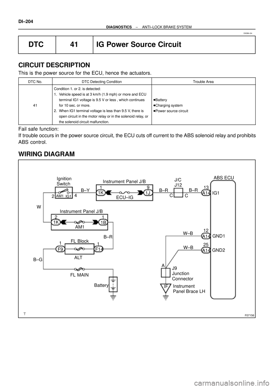
DTC 41 IG Power Source Circuit
CIRCUIT DESCRIPTION
This is the power source for the ECU, hence the actuators.
DTC No.DTC Detecting ConditionTrouble Area
41
Condition 1. or 2. is detected:
1. Vehicle speed is at 3 km/h (1.9 mph) or more and ECU
terminal IG1 voltage is 9.5 V or less , which continues
for 10 sec. or more.
2. When IG1 terminal voltage is less than 9.5 V, there is
open circuit in the motor relay or in the solenoid relay, or
the solenoid circuit malfunction.
�Battery
�Charging system
�Power source circuit
Fail safe function:
If trouble occurs in the power source circuit, the ECU cuts off current to the ABS solenoid relay and prohibits
ABS control.
WIRING DIAGRAM
DI03M±04
Page 2357 of 4592
F00073
ECU±IGECU±IG
Instrument
Panel J/BECU±IG
± DIAGNOSTICSANTI±LOCK BRAKE SYSTEM
DI±205
INSPECTION PROCEDURE
1 Check ECU±IG fuse.
PREPARATION:
Remove ECU±IG fuse from Instrument Panel J/B.
CHECK:
Check continuity of ECU±IG fuse.
OK:
Continuity
NG Check for short circuit in all the harness and
components connected to ECU±IG fuse (See at-
tached wiring diagram).
OK
2 Check battery positive voltage.
OK:
Voltage: 10 ± 14 V
NG Check and repair the charging system (See Pub.
No. RM654U on page CH±1).
OK
Page 2364 of 4592
DI±212
± DIAGNOSTICSANTI±LOCK BRAKE SYSTEM
4 Check battery positive voltage.
CHECK:
Check the battery positive voltage.
OK:
10 ± 14 V
NG Check and repair the charging system (See Pub.
No. RM654U on page CH±1).
OK
5 Check ABS warning light.
PREPARATION:
(a) Disconnect the connector from the ABS ECU.
(b) Turn the ignition switch ON.
CHECK:
Check the ABS warning light goes off.
OK Check and replace ABS ECU.
NG
Check for short circuit in harness and connector between ABS warning light, DLC1, DLC2, and
ABS ECU (See page IN±29).
Page 2442 of 4592
AB0119H01298H01299
(±) (+)ONAirbag Sensor Assembly
ACC
IG2
DI±290
± DIAGNOSTICSSUPPLEMENTAL RESTRAINT SYSTEM
DTC B1100/31 Airbag Sensor Assembly Malfunction
CIRCUIT DESCRIPTION
The airbag sensor assembly consists of a airbag sensor, safing sensor, drive circuit, diagnosis circuit and
ignition control, etc.
It receives signals from the airbag sensor, judges whether or not the SRS must be activated, and detects
diagnosis system malfunction.
DTC B1100/31 is recorded when occurrence of a malfunction in the airbag sensor assembly is detected.
DTC No.DTC Detecting ConditionTrouble Area
B1100/31�Airbag sensor assembly malfunction�Airbag sensor assembly
INSPECTION PROCEDURE
HINT:
When a malfunction code other than code B1100/31 is displayed at the same time, first repair the malfunction
indicated by the malfunction code other than code B1100/31.
1 Prepare for inspection. (See step 1 on page DI±305)
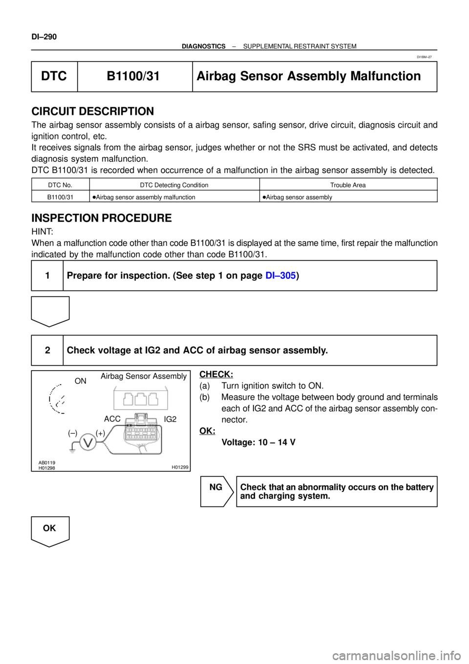
2 Check voltage at IG2 and ACC of airbag sensor assembly.
CHECK:
(a) Turn ignition switch to ON.
(b) Measure the voltage between body ground and terminals
each of IG2 and ACC of the airbag sensor assembly con-
nector.
OK:
Voltage: 10 ± 14 V
NG Check that an abnormality occurs on the battery
and charging system.
OK
DI1BM±27
Page 2459 of 4592
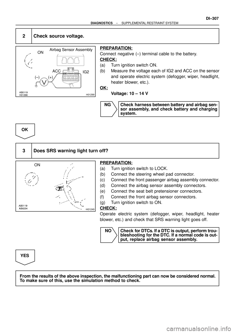
AB0119H01298H01299
Airbag Sensor Assembly
ON
ACC
IG2
(+) (±)
H01249
ON
± DIAGNOSTICSSUPPLEMENTAL RESTRAINT SYSTEM
DI±307
2 Check source voltage.
PREPARATION:
Connect negative (±) terminal cable to the battery.
CHECK:
(a) Turn ignition switch ON.
(b) Measure the voltage each of IG2 and ACC on the sensor
and operate electric system (defogger, wiper, headlight,
heater blower, etc.).
OK:
Voltage: 10 ± 14 V
NG Check harness between battery and airbag sen-
sor assembly, and check battery and charging
system.
OK
3 Does SRS warning light turn off?
PREPARATION:
(a) Turn ignition switch to LOCK.
(b) Connect the steering wheel pad connector.
(c) Connect the front passenger airbag assembly connector.
(d) Connect the airbag sensor assembly connectors.
(e) Connect the seat belt pretensioner connectors.
(f) Connect the front airbag sensor connectors.
(g) Turn ignition switch to ON.
CHECK:
Operate electric system (defogger, wiper, headlight, heater
blower, etc.) and check that SRS warning light goes off.
NO Check for DTCs. If a DTC is output, perform trou-
bleshooting for the DTC. If a normal code is out-
put, replace airbag sensor assembly.
YES
From the results of the above inspection, the malfunctioning part can now be considered normal.
To make sure of this, use the simulation method to check.