Page 3164 of 4592
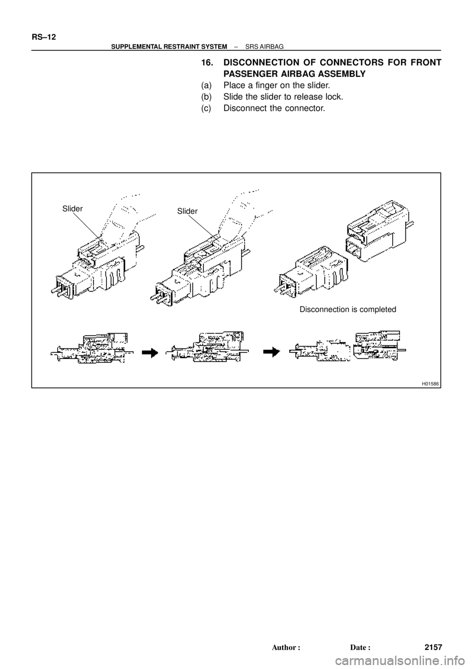
H01586
Slider
Disconnection is completed Slider
RS±12
± SUPPLEMENTAL RESTRAINT SYSTEMSRS AIRBAG
2157 Author�: Date�:
16. DISCONNECTION OF CONNECTORS FOR FRONT
PASSENGER AIRBAG ASSEMBLY
(a) Place a finger on the slider.
(b) Slide the slider to release lock.
(c) Disconnect the connector.
Page 3165 of 4592
H01587
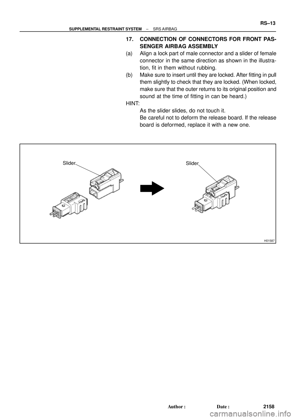
Slider
Slider
± SUPPLEMENTAL RESTRAINT SYSTEMSRS AIRBAG
RS±13
2158 Author�: Date�:
17. CONNECTION OF CONNECTORS FOR FRONT PAS-
SENGER AIRBAG ASSEMBLY
(a) Align a lock part of male connector and a slider of female
connector in the same direction as shown in the illustra-
tion, fit in them without rubbing.
(b) Make sure to insert until they are locked. After fitting in pull
them slightly to check that they are locked. (When locked,
make sure that the outer returns to its original position and
sound at the time of fitting in can be heard.)
HINT:
�As the slider slides, do not touch it.
�Be careful not to deform the release board. If the release
board is deformed, replace it with a new one.
Page 3168 of 4592

RS010±19
W03512
W03513
W03521
Horn Button
Contact Plate
RS±16
± SUPPLEMENTAL RESTRAINT SYSTEMSTEERING WHEEL PAD AND SPIRAL CABLE
2161 Author�: Date�:
INSPECTION
1. VEHICLE NOT INVOLVED IN COLLISION
(a) Do a diagnostic system check.
(See page DI±626)
(b) Do a visual check which includes the following items with
the steering wheel pad (with airbag) installed in the ve-
hicle.
Check cuts, minute cracks or marked discoloration on the
steering wheel pad top surface and in the grooved por-
tion.
2. VEHICLE INVOLVED IN COLLISION AND AIRBAG IS
NOT DEPLOYED
(a) Do a diagnostic system check.
(See page DI±626)
(b) Do a visual check which includes the following items with
the steering wheel pad (with airbag) removed from the ve-
hicle.
�Check cuts, minute cracks or marked discoloration
on the steering wheel pad top surface and in the
grooved portion.
�Check cuts and cracks in wire harnesses, and chip-
ping in connectors.
�Check the deformation of the horn button contact
plate on the steering wheel.
HINT:
�If the horn button contact plate of the steering wheel is de-
formed, never repair it. Always replace the steering wheel
assembly with a new one.
Page 3169 of 4592

W03651
± SUPPLEMENTAL RESTRAINT SYSTEMSTEERING WHEEL PAD AND SPIRAL CABLE
RS±17
2162 Author�: Date�: �
There should be no interference between the steering
wheel pad and steering wheel, and the clearance should
be uniform all the way around when the new steering
wheel pad is installed on the steering wheel.
CAUTION:
For removal and installation of the steering wheel pad, see
page SR±11 and SR±16, and be sure to follow the correct
procedure.
3. VEHICLE INVOLVED IN COLLISION AND AIRBAG IS
DEPLOYED
(a) Do a diagnostic system check.
(See page DI±626)
(b) Do a visual check which includes the following items with
the steering wheel pad (with airbag) removed from the ve-
hicle.
�Check the deformation on the horn button contact
plate of the steering wheel.
�Check the damage on the spiral cable connector
and wire harness.
HINT:
�If the horn button contact plate of the steering wheel is de-
formed, never repair it. Always replace the steering wheel
assembly with a new one.
�There should be no interference between the steering
wheel pad and steering wheel, and the clearance should
be uniform all the way around when the new steering
wheel pad is installed on the steering wheel.
Page 3170 of 4592

RS011±19
AB0152
SST RS±18
± SUPPLEMENTAL RESTRAINT SYSTEMSTEERING WHEEL PAD AND SPIRAL CABLE
2163 Author�: Date�:
DISPOSAL
HINT:
When scrapping vehicle equipped with an SRS or disposing of
a steering wheel pad (with airbag), always first deploy the air-
bag in accordance with the procedure described below. If any
abnormality occurs with the airbag deployment, contact the
SERVICE DEPT. of TOYOTA MOTOR SALES, U.S.A., INC.
When disposing of a steering wheel pad with an airbag
deployed in a collision, follow the same procedure given in step
1±(d) in ºDISPOSALº.
CAUTION:
�Never dispose of a steering wheel pad which has an
undeployed airbag.
�The airbag produces a sizeable exploding sound
when it deploys, so perform the operation out±of±
doors and where it will not create a nuisance to
nearby residents.
�When deploying the airbag, always use the specified
SST (SRS Airbag Deployment Tool). Perform the op-
eration in a place away from electrical noise.
SST 09082±00700
�When deploying an airbag, perform the operation at
least 10 m (33 ft) away from the steering wheel pad.
�The steering wheel pad is very hot when the airbag is
deployed, so leave it alone for at least 30 minutes af-
ter deployment.
�Use gloves and safety glasses when handling a steer-
ing wheel pad with the deployed airbag.
�Always wash your hands with water after completing
the operation.
�Do not apply water, etc. to a steering wheel pad with
the deployed airbag.
Page 3171 of 4592

AB0158
SSTBattery
AB0152
SST
AB0158
SSTBattery
H01580
SST
W03515
± SUPPLEMENTAL RESTRAINT SYSTEMSTEERING WHEEL PAD AND SPIRAL CABLE
RS±19
2164 Author�: Date�:
1. AIRBAG DEPLOYMENT WHEN SCRAPPING VE-
HICLE
HINT:
Have a battery ready as the power source to deploy the airbag.
(a) Check functioning of the SST.
CAUTION:
When deploying the airbag, always use the specified SST:
SRS Airbag Deployment Tool.
SST 09082±00700
(1) Connect the SST to the battery.
Connect the red clip of the SST to the battery posi-
tive (+) terminal and the black clip to the battery neg-
ative (±) terminal.
HINT:
Do not connect the yellow connector which will be connected
with the supplemental restraint system.
(2) Check functioning of the SST.
Press the SST activation switch, and check that the
LED of the SST activation switch lights up.
CAUTION:
If the LED lights up when the activation switch is not being
pressed, SST malfunction is probable, so definitely do not
use the SST.
(b) Install the SST.
CAUTION:
Check that there is no looseness in the steering wheel and
steering wheel pad.
(1) Remove the steering column lower cover.
Remove the 3 screws and steering column lower
cover as shown in the illustration.
(2) Disconnect the airbag connector of the spiral cable.
Page 3172 of 4592
 or more
R06753
RS±20
± SUPPLEMENTAL RESTRAINT SYSTEMSTEERING WHEEL PAD AND SPIRAL CABLE
2165 Author�: Date�:
(3) Connect the SST connector to the airbag connector
of t")
W03508SST
R13455
10 m (33 ft) or more
R06753
RS±20
± SUPPLEMENTAL RESTRAINT SYSTEMSTEERING WHEEL PAD AND SPIRAL CABLE
2165 Author�: Date�:
(3) Connect the SST connector to the airbag connector
of the spiral cable.
SST 09082±00700
(4) Move the SST at least 10 m (33 ft) away from the
front of the vehicle.
(5) Close all the doors and windows of the vehicle.
NOTICE:
Take care not to damage the SST wire harness.
(6) Connect the SST red clip to the battery positive (+)
terminal and the black clip to the negative (±) termi-
nal.
(c) Deploy the airbag.
(1) Confirm that no one is inside the vehicle or within 10
m (33 ft) area around the vehicle.
(2) Press the SST activation switch and deploy the air-
bag.
HINT:
The airbag deploys simultaneously as the LED of the SST ac-
tivation switch lights up.
(d) Dispose of steering wheel pad (with airbag).
CAUTION:
�The steering wheel pad is very hot when the airbag is
deployed, so leave it alone for at least 30 minutes af-
ter deployment.
�Use gloves and safety glasses when handling a steer-
ing wheel pad with the deployed airbag.
�Always wash your hands with water after completing
the operation.
�Do not apply water, etc. to a steering wheel pad with
the deployed airbag.
(1) When scrapping a vehicle, deploy the airbag and
scrap the vehicle with the steering wheel pad still
installed.
(2) When moving a vehicle for scrapping which has a
steering wheel pad with deployed airbag, use
gloves and safety glasses.
Page 3173 of 4592

W03520
Inflacter Cover
Connector
AB0163
Wire Harness
Diameter
Stripped Wire Harness Section
H06693
L
M
± SUPPLEMENTAL RESTRAINT SYSTEMSTEERING WHEEL PAD AND SPIRAL CABLE
RS±21
2166 Author�: Date�:
2. DEPLOYMENT WHEN DISPOSING OF STEERING
WHEEL PAD ONLY
NOTICE:
�When disposing of the steering wheel pad (with air-
bag) only, never use the customers vehicle to deploy
the airbag.
�Be sure to follow the procedure given below when de-
ploying the airbag.
HINT:
Have a battery ready as the power source to deploy the airbag.
(a) Remove the steering wheel pad.
(See page SR±11)
CAUTION:
When storing the steering wheel pad, keep the upper sur-
face of the pad facing upward.
(b) Remove the steering wheel pad connector.
Remove the connector on the rear surface of the steering
wheel pad from the bracket.
(c) Using a service±purpose wire harness, tie down the
steering wheel pad to the disc wheel.
Wire harness: Stripped wire harness section
1.25 mm
2
or more (0.0019 in2. or more).
CAUTION:
If a wire harness which is too thin or some other thing is
used to tie down the steering wheel pad, it may be snapped
by the shock when the airbag is deployed. This is highly
dangerous. Always use a wire harness for vehicle use
which is at least 1.25 mm
2
(0.0019 in2).
HINT:
To calculate the square of the stripped wire harness section:
Square = 3.14 x (Diameter)
2
divided by 4
(1) Install the 2 bolts with washers in the 2 bolt holes in
the steering wheel pad.
Bolt:
L: 35.0 mm (1.387 in.)
M: 6.0 mm (0.236 in.)
Pitch: 1.0 mm (0.039 in.)
NOTICE:
�Tighten the bolts by hand until the bolts become diffi-
cult to turn.
�Do not tighten the bolts too much.