Page 2861 of 4592
 AIRBAG SENSOR ASSEMBLY
(1) Never reuse the airbag sensor assembly involved
in a collision when the SRS has deployed.
(2) The connectors")
± INTRODUCTIONFOR ALL OF VEHICLES
IN±15
15 Author�: Date�:
(g) AIRBAG SENSOR ASSEMBLY
(1) Never reuse the airbag sensor assembly involved
in a collision when the SRS has deployed.
(2) The connectors to the airbag sensor assembly
should be connected or disconnected with the sen-
sor mounted on the floor. If the connectors are con-
nected or disconnected while the airbag sensor as-
sembly is not mounted to the floor, it could cause
undesired ignition of the supplemental restraint sys-
tem.
(3) Work must be started after 90 seconds from the
time the ignition switch is turned to the ºLOCKº posi-
tion and the negative (±) terminal cable is discon-
nected from the battery, even if only loosing the set
bolts of the airbag sensor assembly.
(h) WIRE HARNESS AND CONNECTOR
The SRS wire harness is integrated with the instrument
panel wire harness assembly. All the connectors in the
system are a standard yellow color. If the SRS wire har-
ness becomes disconnected or the connector becomes
broken due to an accident, etc., repair or replace it as
shown on page RS±73 in Pub. No. RM654U .
Page 2930 of 4592
 Check the steering wheel freeplay. (See page SR±8)
(b) Check the steering linkage fo")
MA00N±01
N01022
± MAINTENANCECHASSIS
MA±7
50 Author�: Date�:
CHASSIS
INSPECTION
1. INSPECT STEERING LINKAGE
(a) Check the steering wheel freeplay. (See page SR±8)
(b) Check the steering linkage for looseness or damage.
Check that:
�Tie rod ends do not have excessive play.
�Dust seals and boots are not damaged.
�Boot clamps are not loose.
2. INSPECT SRS AIRBAG (See page RS±2)
3. INSPECT STEERING GEAR HOUSING OIL
Check the steering gear housing for oil leakage.
4. INSPECT DRIVE SHAFT BOOTS
Check the drive shaft boots for clamp looseness, leakage or
damage.
5. INSPECT BALL JOINTS AND DUST COVERS
(a) Inspect the ball joints for excessive looseness.
�Jack up the front of the vehicle and place wooden
blocks with a height of 180 ± 200 mm (7.09 ± 7.87
in.) under the front tires.
�Lower the jack until there is about half a load on the
front coil spring. Place stands under the vehicle for
safety.
�Check that the front wheels are pointing straight
ahead, and block them with chocks.
�Using a lever, pry up the end of the lower arm, and
check the amount of play.
Maximum ball joint vertical play: 0 mm (0 in.)
If there is play, replace the ball joint.
(b) Check the dust cover for damage.
6. CHECK TRANSAXLE OIL (FLUID)
(a) Visually check the transaxle for oil (fluid) leakage.
If leakage is found, check for the cause and repair.
7. REPLACE TRANSAXLE OIL (FLUID)
(a) M/T:
Replace the transaxle oil.
S51: (See page MX±4)
E153: (See page MX±4)
(b) A/T:
Replace the transaxle fluid.
A140E: (See page DI±389)
A541E: (See page DI±438)
Page 3123 of 4592
PP0MQ±01
PP±98
± PREPARATIONSUPPLEMENTAL RESTRAINT SYSTEM
150 Author�: Date�:
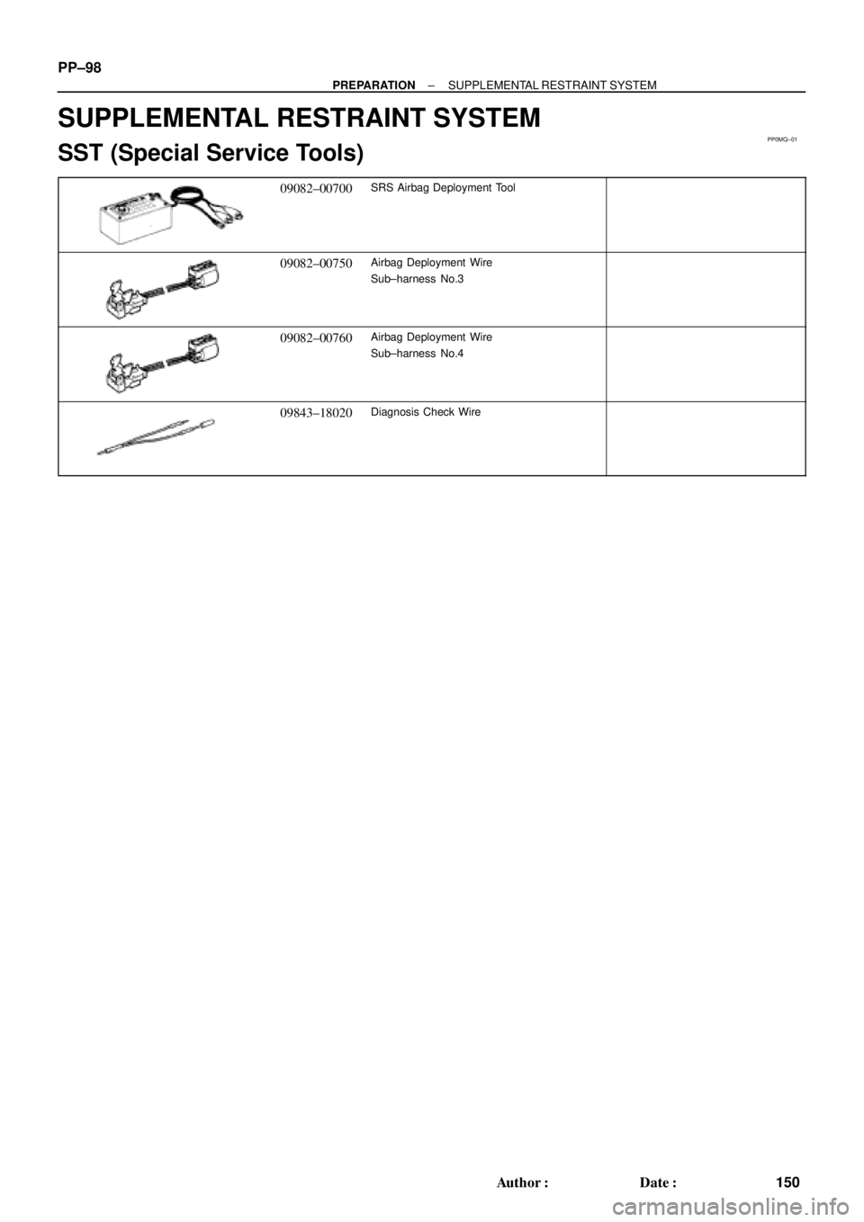
SUPPLEMENTAL RESTRAINT SYSTEM
SST (Special Service Tools)
09082±00700SRS Airbag Deployment Tool
09082±00750Airbag Deployment Wire
Sub±harness No.3
09082±00760Airbag Deployment Wire
Sub±harness No.4
09843±18020Diagnosis Check Wire
Page 3124 of 4592
PP1XL±01
± PREPARATIONSUPPLEMENTAL RESTRAINT SYSTEM
PP±99
151 Author�: Date�:
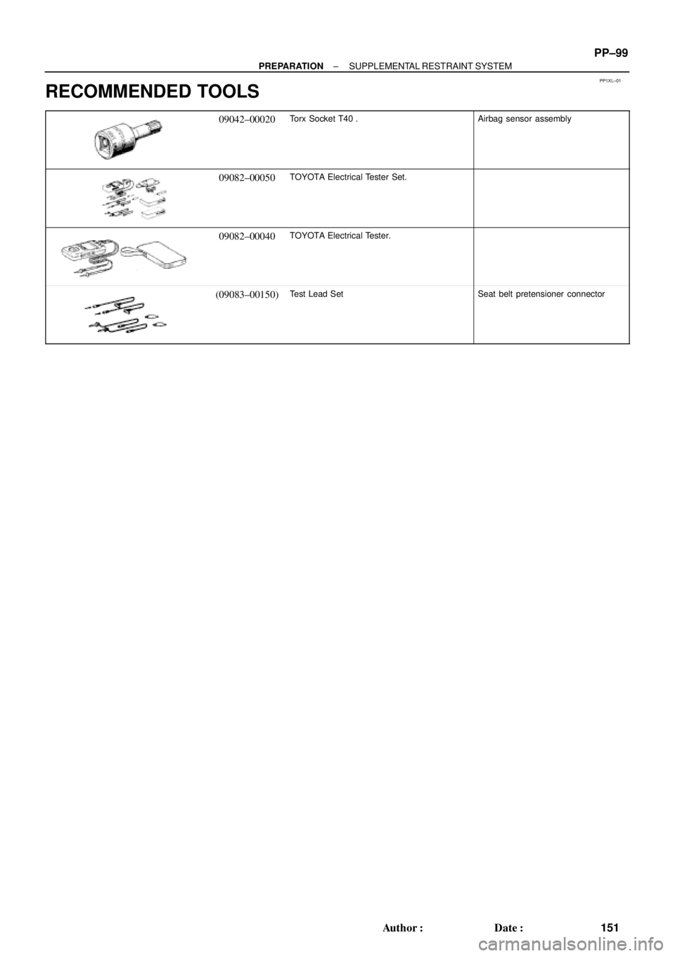
RECOMMENDED TOOLS
09042±00020Torx Socket T40 .Airbag sensor assembly
09082±00050TOYOTA Electrical Tester Set.
09082±00040TOYOTA Electrical Tester.
(09083±00150)Test Lead SetSeat belt pretensioner connector
Page 3125 of 4592
PP0MS±01
PP±100
± PREPARATIONSUPPLEMENTAL RESTRAINT SYSTEM
152 Author�: Date�:
EQUIPMENT
Torque wrench
Bolt: Length: 35 mm (1.38 in.) Pitch: 1.0 mm (0.039 in.)
Diam.: 6.0 mm (0.236 in.)Airbag disposal
Tire Width: 185 mm (7.28 in.) Inner diam.: 360mm (14.17 in.)Airbag disposal
Tire with disc wheel Width: 185 mm (7.28 in.)
Inner diam.: 360 mm (14.17 in.)Airbag disposal
Vinyl bagAirbag disposal
Page 3153 of 4592

RS01Y±22
± SUPPLEMENTAL RESTRAINT SYSTEMSRS AIRBAG
RS±1
2146 Author�: Date�:
SRS AIRBAG
PRECAUTION
NOTICE:
�The CAMRY is equipped with SRS, which comprises a driver airbag, front passenger airbag,
and side airbag. Failure to carry out service operations in the correct sequence could cause
the SRS to unexpectedly deploy during servicing, possibly leading to a serious accident. Fur-
ther, if a mistake is made in servicing the SRS, it is possible that the SRS may fail to operate
when required. Before performing servicing (including removal or installation of parts, inspec-
tion or replacement), be sure to read the following items carefully, then follow the correct proce-
dures described in the repair manual.
�Malfunction symptoms of the SRS are difficult to confirm, so the DTCs become the most impor-
tant source of information when troubleshooting. When troubleshooting the SRS, always in-
spect the DTCs before disconnecting the battery.
�Even in cases of a minor collision where the SRS does not deploy, the steering wheel pad, front
passenger airbag assembly, side airbag assembly (TMC made and TMMK made), airbag sensor
assembly, front airbag sensor and side airbag sensor assembly should be inspected.
(See page RS±16, RS±29, RS±41, RS±54, RS±60, RS±65 and RS±70)
�Never use SRS parts from another vehicle. When replacing parts, replace them with new parts.
�Never disassemble and repair the steering wheel pad, front passenger airbag assembly, side
airbag assembly, airbag sensor assembly, front airbag sensor or side airbag sensor assembly
in order to reuse it.
�If the steering wheel pad, front passenger airbag assembly, side airbag assembly, airbag sen-
sor assembly, front airbag sensor or side airbag sensor assembly has been dropped, or if there
are cracks, dents or other defects in the case, bracket or connector, replace them with new
ones.
�Use a volt/ohmmeter with high impedance (10 kW/V minimum) for troubleshooting the system's
electrical circuits.
�Information labels are attached to the periphery of the SRS components. Follow the instruc-
tions on the notices.
�After work on the SRS is completed, perform the SRS warning light check (See page DI±626).
�If the vehicle is equipped with a mobile communication system, refer to the precaution in the
IN section.
CAUTION:
�Work must be started 90 seconds after the ignition switch is turned to the ºLOCKº position and
the negative (±) terminal cable is disconnected from the battery.
(The SRS is equipped with a back±up power source so that if work is started within 90 seconds
from disconnecting the negative (±) terminal cable of the battery, the SRS may be deployed.)
�When the negative (±) terminal cable is disconnected from the battery, the memory of the clock
and audio system will be canceled. So before starting work, make a record of the contents mem-
orized in the audio memory system. When work is finished, reset the audio systems as they
were before and adjust the clock. To avoid erasing the memory in each memory system, never
use a back± up power supply from outside the vehicle.
�Before repairs, remove the airbag sensor if shocks are likely to be applied to the sensor during
repairs.
�Do not expose the steering wheel pad, front passenger airbag assembly, side airbag assembly,
airbag sensor assembly, front airbag sensor or side airbag sensor assembly directly to hot air
or flames.
Page 3154 of 4592

The inflater and bag of the")
RS0ET±01
W03512
R09725Spiral Cable
W03511
H01347
H02610
RS±2
± SUPPLEMENTAL RESTRAINT SYSTEMSRS AIRBAG
2147 Author�: Date�:
OPERATION
1. STEERING WHEEL PAD (with AIRBAG)
The inflater and bag of the SRS are stored in the steering wheel
pad and cannot be disassembled. The inflater contains a squib,
igniter charge, gas generant, etc., and inflates the bag when
instructed by the airbag sensor assembly.
2. SPIRAL CABLE (in COMBINATION SWITCH)
A spiral cable is used as an electrical joint from the vehicle body
side to the steering wheel.
3. FRONT PASSENGER AIRBAG ASSEMBLY
The inflater and bag of the SRS are stored in the front passen-
ger airbag assembly and cannot be disassembled. The inflater
contains a squib, igniter charge and gas generant, etc., and in-
flates the bag when instructed by the airbag sensor assembly.
4. SIDE AIRBAG ASSEMBLY
The inflater and bag of the SRS side airbag are stored in the
side airbag assembly and cannot be disassembled. The inflater
contains a squib, igniter charge and gas generant, etc., and in-
flates the bag when instructed by the side airbag sensor assem-
bly.
5. SEAT BELT PRETENSIONER
The seat belt pretensioner system is a component of the front
seat outer belt. The pretensioner contains a squib, gas gener-
ant, wire, piston, etc., and operates in the event of a frontal colli-
sion.
Page 3155 of 4592

H02309
H02266
H08235
H03284
± SUPPLEMENTAL RESTRAINT SYSTEMSRS AIRBAG
RS±3
2148 Author�: Date�:
6. SRS WARNING LIGHT
The SRS warning light is located on the combination meter. It
goes on to alert the driver of trouble in the system when a mal-
function is detected in the airbag sensor assembly self±diagno-
sis. In normal operation conditions when the ignition switch is
turned to the ACC or ON position, the light goes on for about 6
seconds and then goes off.
7. AIRBAG SENSOR ASSEMBLY
The airbag sensor assembly is mounted on the floor inside the
lower center finish panel. The airbag sensor assembly consists
of an airbag sensor, safing sensor, diagnosis circuit, ignition
control and drive circuit, etc. It receives signals from the airbag
sensor and judges whether the SRS must be activated or not.
8. FRONT AIRBAG SENSOR
A front airbag sensor is mounted inside each of the side mem-
bers. The sensor unit is a mechanical type. When the sensor
detects deceleration force above a predetermined limit, contact
is made in the sensor, sending a signal to the airbag sensor as-
sembly. The sensor cannot be disassembled.
9. SIDE AIRBAG SENSOR ASSEMBLY
The side airbag sensor assembly is mounted in the LH and RH
center pillars. The side airbag sensor assembly consists of a lat-
eral deceleration sensor, safing sensor and diagnosis circuit,
etc. It receives signals to the airbag sensor assembly to judge
from the side airbag sensors whether the SRS side airbag must
be activated or not.