Page 2461 of 4592
AB0117H01293H01295
Airbag Sensor Assembly
LOCK
± DIAGNOSTICSSUPPLEMENTAL RESTRAINT SYSTEM
DI±309
INSPECTION PROCEDURE
Always lit up, when ignition switch is in LOCK position
1 Prepare for inspection. (See step 1 on page DI±305)
2 Does SRS warning light turn off?
PREPARATION:
(a) Turn ignition switch to LOCK.
(b) Disconnect negative (±) terminal cable from the battery,
and wait at least for 90 seconds.
(c) Disconnect the airbag sensor assembly connector.
(d) Connect negative (±) terminal cable to the battery.
CHECK:
Check operation of SRS warning light.
NO Check SRS warning light circuit or terminal AB
circuit of DLC1.
YES
Replace airbag sensor assembly.
Page 2462 of 4592
N14677
Fuse
AB0119H01300
H01301
Airbag Sensor Assembly
ON
LA
(+)
(±)
DI±310
± DIAGNOSTICSSUPPLEMENTAL RESTRAINT SYSTEM
Does not light up, when ignition switch is turned to ACC or ON
1 Check ECU±B Fuse.
PREPARATION:
Remove ECU±B fuse.
CHECK:
Check continuity of ECU±B fuse.
OK:
Continuity
HINT:
�Fuse may be burnt out even if it appears to be OK during
visual inspection.
�If fuse is OK, install it.
NG Go to step 5.
OK
2 Prepare for inspection. (See step 1 on page DI±305)
3 Check SRS warning light circuit.
PREPARATION:
(a) Connect negative (±) terminal cable to the battery.
(b) Turn ignition switch to ACC or ON.
CHECK:
Measure the voltage LA terminal of the harness side connector
of the airbag sensor assembly.
OK:
Voltage: 10 ± 14 V
NG Check SRS warning light bulb or repair SRS
warning light circuit.
OK
Page 2463 of 4592
H02755AB0119H10313H10308
ON P/T Squib (LH)
Front Airbag
Sensor (RH)Spiral
Cable
P/T Squib (RH) Front Airbag
Sensor (LH)
P Squib D SquibAirbag Sensor
Assembly
± DIAGNOSTICSSUPPLEMENTAL RESTRAINT SYSTEM
DI±311
4 Does SRS warning light come on?
PREPARATION:
(a) Disconnect negative (±) terminal cable from the battery.
(b) Connect the airbag sensor assembly connector.
(c) Connect negative (±) terminal cable to the battery, and
wait at least for 2 seconds.
(d) Turn ignition switch to ACC or ON.
CHECK:
Check operation of SRS warning light.
NO Check terminal LA of airbag sensor assembly.
If normal, replace airbag sensor assembly.
YES
From the results of the above inspection, the malfunctioning part can now be considered normal.
To make sure of this, use simulation method to check.
Page 2465 of 4592
H08301H10309
LG±R P±B
B
BJ2 Junction
ConnectorAirbag Sensor
Assembly
C519
Tc
11
LG±R 11
Tc
E1DLC1
3 BR
A
BR
ECEC BR A
Junction
Connector
6
J6B
J7 C
BR 3
E1Tc DLC2 LG±R
4
B IG3
IG3
BR
J20
Junction Connector
A A BR J20
Junction Connector
± DIAGNOSTICSSUPPLEMENTAL RESTRAINT SYSTEM
DI±313
Tc Terminal Circuit
CIRCUIT DESCRIPTION
By connecting terminals Tc and E1 of the DLC1 the airbag sensor assembly is set in the DTC output mode.
The DTCs are displayed by blinking the SRS warning light.
WIRING DIAGRAM
DI1BQ±12
Page 2467 of 4592

AB0118
R14304AB0119
H00031
ACCON
orTc
(+)
(±)
AB0117 AB0118 AB0119H01302H01303
LOCK
ACCON
or
Airbag Sensor Assembly
Tc
± DIAGNOSTICSSUPPLEMENTAL RESTRAINT SYSTEM
DI±315
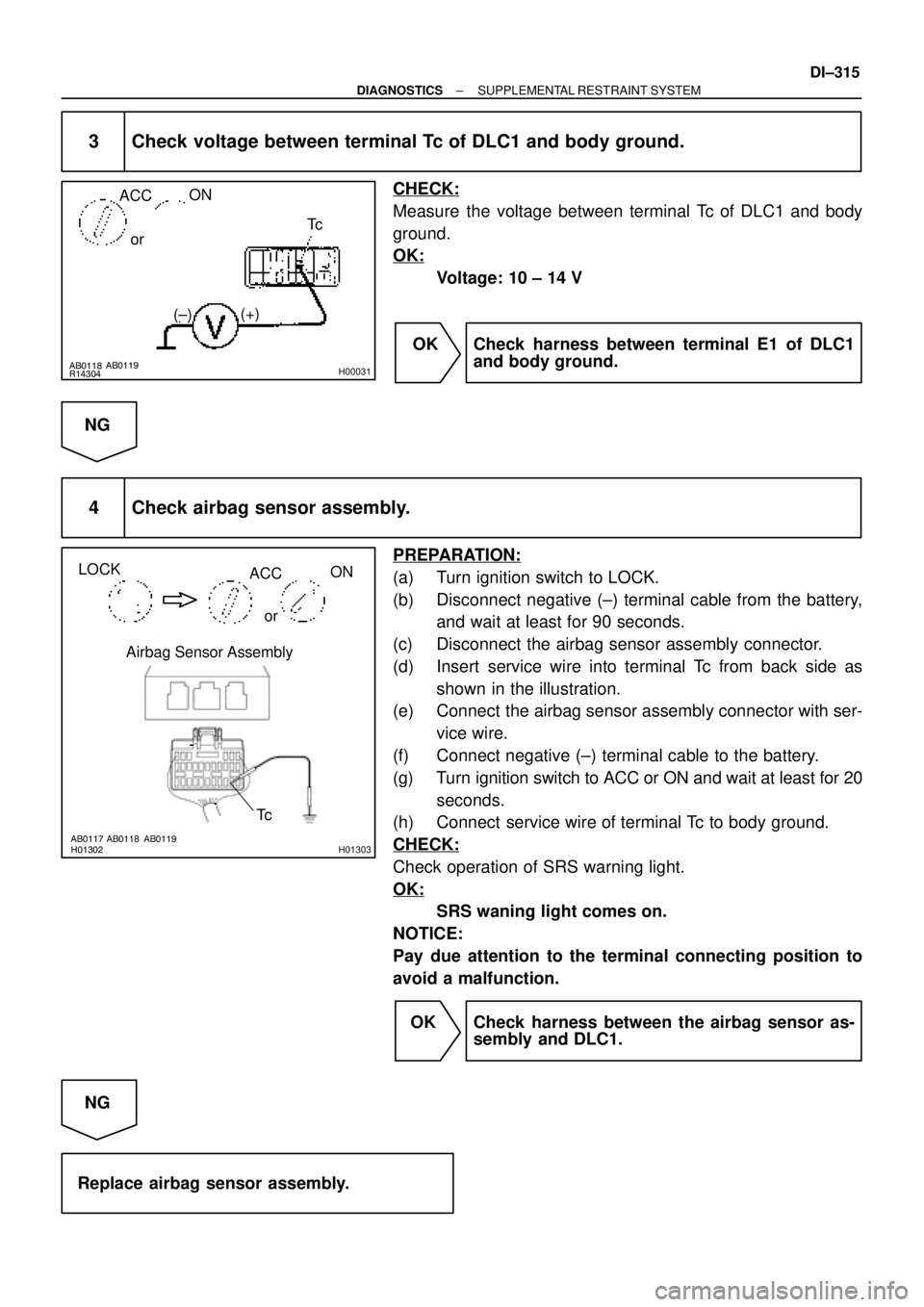
3 Check voltage between terminal Tc of DLC1 and body ground.
CHECK:
Measure the voltage between terminal Tc of DLC1 and body
ground.
OK:
Voltage: 10 ± 14 V
OK Check harness between terminal E1 of DLC1
and body ground.
NG
4 Check airbag sensor assembly.
PREPARATION:
(a) Turn ignition switch to LOCK.
(b) Disconnect negative (±) terminal cable from the battery,
and wait at least for 90 seconds.
(c) Disconnect the airbag sensor assembly connector.
(d) Insert service wire into terminal Tc from back side as
shown in the illustration.
(e) Connect the airbag sensor assembly connector with ser-
vice wire.
(f) Connect negative (±) terminal cable to the battery.
(g) Turn ignition switch to ACC or ON and wait at least for 20
seconds.
(h) Connect service wire of terminal Tc to body ground.
CHECK:
Check operation of SRS warning light.
OK:
SRS waning light comes on.
NOTICE:
Pay due attention to the terminal connecting position to
avoid a malfunction.
OK Check harness between the airbag sensor as-
sembly and DLC1.
NG
Replace airbag sensor assembly.
Page 2468 of 4592
AB0119H01304H01305
LOCKAirbag Sensor Assembly
Tc
(+)
(±)
DI±316
± DIAGNOSTICSSUPPLEMENTAL RESTRAINT SYSTEM
If the DTC is displayed without a DTC check procedure, perform the following
troubleshooting.
1 Check resistance between terminal Tc of airbag sensor assembly and body
ground.
PREPARATION:
(a) Turn ignition switch to LOCK.
(b) Disconnect negative (±) terminal cable from the battery,
and wait at least for 90 seconds.
(c) Disconnect the airbag sensor assembly connector.
CHECK:
Check resistance between terminal Tc of the airbag sensor as-
sembly connector and body ground.
OK:
Resistance: 1 MW or Higher
NG Repair or replace harness or connector.
OK
Replace airbag sensor assembly.
Page 2813 of 4592

IN0CQ±03
BO4111
Negative Cable
IN±10
± INTRODUCTIONFOR ALL OF VEHICLES
10 Author�: Date�:
FOR ALL OF VEHICLES
PRECAUTION
1. FOR VEHICLES EQUIPPED WITH SRS AIRBAG AND
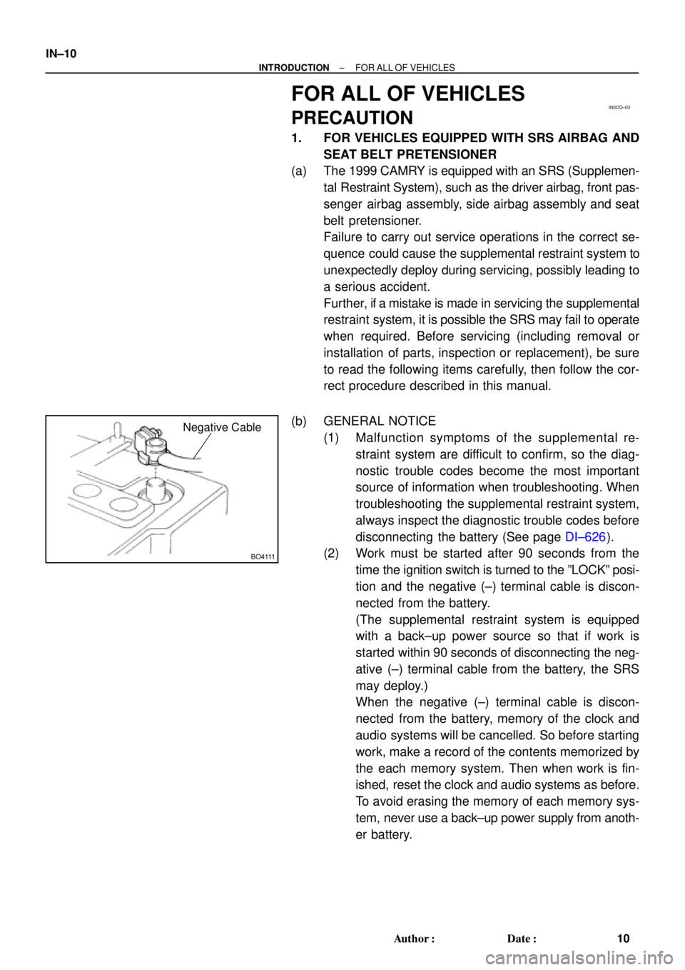
SEAT BELT PRETENSIONER
(a) The 1999 CAMRY is equipped with an SRS (Supplemen-
tal Restraint System), such as the driver airbag, front pas-
senger airbag assembly, side airbag assembly and seat
belt pretensioner.
Failure to carry out service operations in the correct se-
quence could cause the supplemental restraint system to
unexpectedly deploy during servicing, possibly leading to
a serious accident.
Further, if a mistake is made in servicing the supplemental
restraint system, it is possible the SRS may fail to operate
when required. Before servicing (including removal or
installation of parts, inspection or replacement), be sure
to read the following items carefully, then follow the cor-
rect procedure described in this manual.
(b) GENERAL NOTICE
(1) Malfunction symptoms of the supplemental re-
straint system are difficult to confirm, so the diag-
nostic trouble codes become the most important
source of information when troubleshooting. When
troubleshooting the supplemental restraint system,
always inspect the diagnostic trouble codes before
disconnecting the battery (See page DI±626).
(2) Work must be started after 90 seconds from the
time the ignition switch is turned to the ºLOCKº posi-
tion and the negative (±) terminal cable is discon-
nected from the battery.
(The supplemental restraint system is equipped
with a back±up power source so that if work is
started within 90 seconds of disconnecting the neg-
ative (±) terminal cable from the battery, the SRS
may deploy.)
When the negative (±) terminal cable is discon-
nected from the battery, memory of the clock and
audio systems will be cancelled. So before starting
work, make a record of the contents memorized by
the each memory system. Then when work is fin-
ished, reset the clock and audio systems as before.
To avoid erasing the memory of each memory sys-
tem, never use a back±up power supply from anoth-
er battery.
Page 2814 of 4592

W02655
Marks
± INTRODUCTIONFOR ALL OF VEHICLES
IN±11
11 Author�: Date�:
(3) Even in cases of a minor collision where the SRS
does not deploy, the steering wheel pad, front pas-
senger airbag assembly, side airbag assembly and
seat belt pretensioner should be inspected (See
page RS±16, RS±29, and BO±127).
(4) Never use SRS parts from another vehicle. When
replacing parts, replace them with new parts.
(5) Before repairs, remove the airbag sensor if shocks
are likely to be applied to the sensor during repairs.
(6) Never disassemble and repair the airbag sensor as-
sembly, steering wheel pad, front passenger airbag
assembly, side airbag assembly or seat belt preten-
sioner.
(7) If the airbag sensor assembly, steering wheel pad,
front passenger airbag assembly, side airbag as-
sembly or seat belt pretensioner has been dropped,
or if there are cracks, dents or other defects in the
case, bracket or connector, replace them with new
ones.
(8) Do not directly expose the airbag sensor assembly,
steering wheel pad, front passenger airbag assem-
bly, side airbag assembly or seat belt pretensioner
to hot air or flames.
(9) Use a volt/ohmmeter with high impedance (10 kW/V
minimum) for troubleshooting of the electrical cir-
cuit.
(10) Information labels are attached to the periphery of
the SRS components. Follow the instructions on the
notices.
(11) After work on the supplemental restraint system is
completed, check the SRS warning light (See page
DI±626).
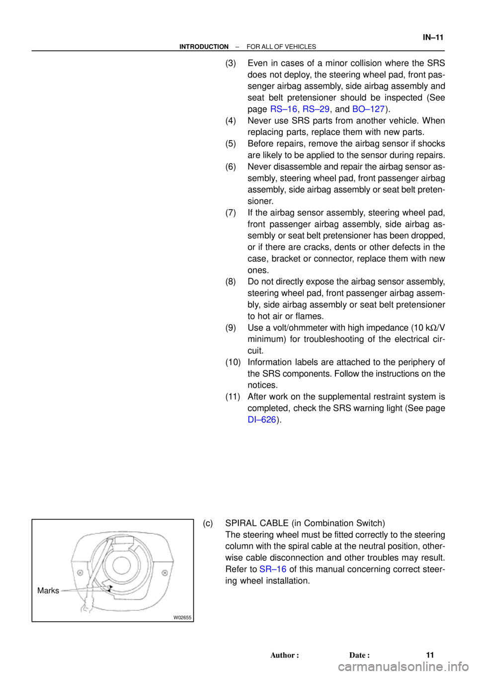
(c) SPIRAL CABLE (in Combination Switch)
The steering wheel must be fitted correctly to the steering
column with the spiral cable at the neutral position, other-
wise cable disconnection and other troubles may result.
Refer to SR±16 of this manual concerning correct steer-
ing wheel installation.