Page 761 of 4592
Z19055
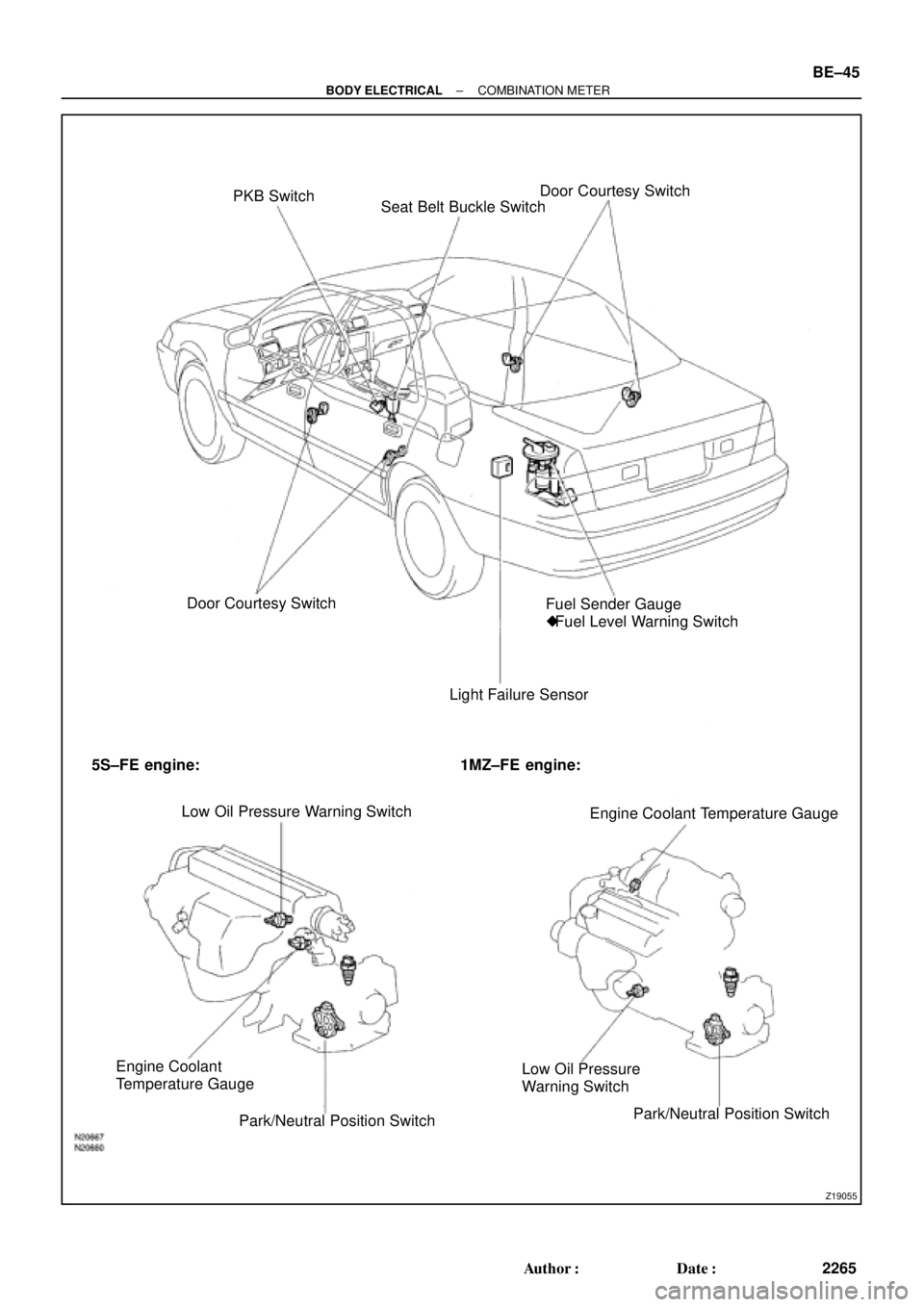
PKB Switch
Seat Belt Buckle SwitchDoor Courtesy Switch
Door Courtesy Switch
Light Failure SensorFuel Sender Gauge
�Fuel Level Warning Switch
5S±FE engine: 1MZ±FE engine:
Low Oil Pressure Warning Switch
Engine Coolant Temperature Gauge
Engine Coolant
Temperature Gauge
Park/Neutral Position SwitchLow Oil Pressure
Warning Switch
Park/Neutral Position Switch
± BODY ELECTRICALCOMBINATION METER
BE±45
2265 Author�: Date�:
Page 762 of 4592

BE0AJ±03
Z18937
Connector ºAº Connector ºBº Connector ºCº
Connector ºAº
Connector ºBº
Connector ºCº
J±13±1±A J±16±1 J±13±1
1 2 3 4 5 6 7 8 9 10 11 12 1314 15 16 1 234 56 78 910111213 1 23456 78910111213
C7
C5
A2 B3
A1
C8
B15
C6
B6
A4
C4
B5
C10 B14
A13
B2
C1
B1
C9
A6
A11
A7
A10
A8
A9
C13
B8
B11
B12A5
C11
B4
B16 C2
A12
A3
B7
C3
C12
B9
B10
B13 F
E
T
S
ODOMETER
Fuel Level Warning
Seat Belt Warning
ABS Warning
Low Oil Pressure Warning
Cruise Control Indicator
Malfunction Indicator
O/D OFF Indicator
Light Failure Warning
Brake Warning
SLIP Indicator
TRAC Indicator
Washer Level Warning
Discharge Warning
Right Turn Indicator
Left Turn Indicator
Security Indicator
L
2
D
N
R
P
Illumination
Hi±Beam Indicator
Open Door Warning
SRS Warning
: Fuel Gauge
: Engine Coolant Temperature Gauge
: Tachometer
: Speedometer
No.
A
B
C1
2
3
4
5
6
7 8
9
10
11
12 13
14
15
16
2 3
4
5
6
7 8
9
10
11 12
131
2
3
4 5
6
7
8
9
10
11
12
13
F
E
T
SEngine coolant temperature sender gauge
Ground
Light failure sensor
Integration relay
Traction ECU
Park/neutral position switch (A/T)
O/D OFF switch (A/T)
IGN fuse
Turn signal switch
ST relay
Fuel sender gauge
Generator
Oil pressure switch
Fuel sender gauge
Parking brake switch and brake fluid level warning switch
Headlight dimmer switch
Headlight dimmer switch
Door courtesy switch
DOME fuse
ECU±B fuse
Airbag sensor assembly
ECM
No.1 Vehicle speed sensor Ground
Turn signal switch ECM
Traction ECU
ABS ECU
Ground No.1 Vehicle speed sensor
GAUGE fuse
Igniter
Security ECU
Cruise control ECU
Washer fluid level warning switch
Light control rheostat
TAIL fuse Park/neutral position switch (A/T) Park/neutral position switch (A/T) Park/neutral position switch (A/T) Park/neutral position switch (A/T)
Park/neutral position switch (A/T)Wire Harness Side
Bulb Check
Relay
N20107 N201081
BE±46
± BODY ELECTRICALCOMBINATION METER
2266 Author�: Date�:
CIRCUIT
Page 768 of 4592

N20217
OFF
ONOhmmeter
Z05732
Warning Light
Ignition
Switch
Battery
1
BE0044
Warning Light
Ignition
Switch
Battery
Z16167
1
2 OFF
ON
N02354
1
2OFF
ON BE±52
± BODY ELECTRICALCOMBINATION METER
2272 Author�: Date�:
18. INSPECT WASHER FLUID LEVEL WARNING SWITCH
(a) Check that no continuity exists between terminals with the
switch OFF (float up).
(b) Check that continuity exists between terminals with the
switch ON (float down).
If operation is not as specified, replace the switch.
19. INSPECT OPEN DOOR WARNING LIGHT
Disconnect the connector from the door courtesy switch and
ground terminal 1 on the wire harness side, and check that the
warning light lights up.
If the warning light does not light up, inspect the bulb or wire har-
ness.
20. INSPECT SEAT BELT WARNING LIGHT
(a) Remove the integration relay from the instrument panel
junction block.
(b) Ground terminal 2 on the integration relay with the con-
nectors still connected.
(c) Turn the ignition switch ON and check that the warning
light lights up.
If the warning light does not light up, inspect the bulb or wire har-
ness.
21. w/o Power seat:
INSPECT BUCKLE SWITCH CONTINUITY
(a) Check that continuity exists between the terminals on the
switch side connector with the switch ON (belt fastened).
(b) Check that no continuity exists between the terminals on
the switch side connector with the switch OFF (belt unfas-
tened).
If operation is not as specified, replace the seat belt inner belt.
22. w/ Power seat:
INSPECT BUCKLE SWITCH CONTINUITY
(a) Check that continuity exists between terminals 1 and 2 on
the switch side connector with the switch ON (belt fas-
tened).
(b) Check that no continuity exists between terminals 1 and
2 on the switch side connector with the switch OFF (belt
unfastened).
If operation is not as specified, replace the seat belt inner belt.
Page 769 of 4592
N20219
Type A:
Type B and C:1
7
9
10
1
7
910
N20220
Type A:
Type B and C:1
7
9
10
1
7910 88
± BODY ELECTRICALCOMBINATION METER
BE±53
2273 Author�: Date�:
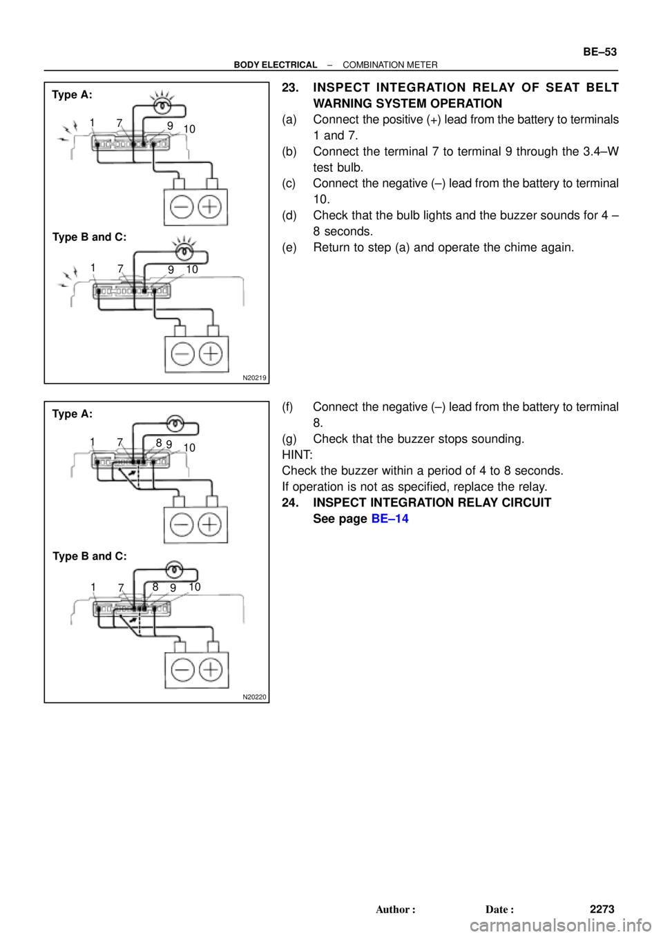
23. INSPECT INTEGRATION RELAY OF SEAT BELT
WARNING SYSTEM OPERATION
(a) Connect the positive (+) lead from the battery to terminals
1 and 7.
(b) Connect the terminal 7 to terminal 9 through the 3.4±W
test bulb.
(c) Connect the negative (±) lead from the battery to terminal
10.
(d) Check that the bulb lights and the buzzer sounds for 4 ±
8 seconds.
(e) Return to step (a) and operate the chime again.
(f) Connect the negative (±) lead from the battery to terminal
8.
(g) Check that the buzzer stops sounding.
HINT:
Check the buzzer within a period of 4 to 8 seconds.
If operation is not as specified, replace the relay.
24. INSPECT INTEGRATION RELAY CIRCUIT
See page BE±14
Page 847 of 4592
BO0KU±01
± BODYSRS AIRBAG
BO±3
2351 Author�: Date�:
SRS AIRBAG
PRECAUTION
The CAMRY is equipped with SRS (Supplemental Restraint System) such as the driver airbag, front passen-
ger airbag, side airbag and seat belt pretensioner. Failure to carry out service operation in the correct se-
quence could cause the SRS to unexpectedly deploy during servicing, possibly leading to a serious acci-
dent. Before servicing (including removal or installation of parts, inspection or replacement), be sure to read
the precautionary notices in the RS section.
Page 855 of 4592
BO0L2±01
H01975
Door Lock
Cylinder
Outside Handle Front Door Belt Moulding
Door Glass
Door FrameFront Door Upper Moulding
Outside
Rear View
Mirror
Door Glass
Run
5.5 (55, 49 in.´lbf)
5.5 (55, 49 in.´lbf)
5.0 (50, 43 in.´lbf)�
Door Lock
23 (230, 17)
Window Regulator
8.0 (80, 69 in.´lbf)
Door Hinge
X6
7.5 (75, 66 in.´lbf)
Regulator
Motor
X3
31 (310, 22)
26 (260, 19)
8.0 (80, 71 in.´lbf)
30 (300, 22)
31 (310, 22)
Door
Check
Door Hinge
26 (260, 19)
Speaker
Power Window Switch Rear Lower
FrameFront Lower
FrameFront Window Upper
Garnish
Inside Handle Bezel
3.5 (35, 31 in.´lbf)
Driver's Side:
Regulator
Motor
Ptdt
N´m (kgf´cm, ft´lbf) : Specified torqueInside Handle
Door Trim
� Precoated part Door Lock StrikerService Hole Cover
± BODYFRONT DOOR
BO±11
2359 Author�: Date�:
FRONT DOOR
COMPONENTS
Page 857 of 4592
N20970
(a)
(b)(b)
N21004
Clip
H01729
: 7 rivets
: clip
: clip
: clip
± BODYFRONT DOOR
BO±13
2361 Author�: Date�:
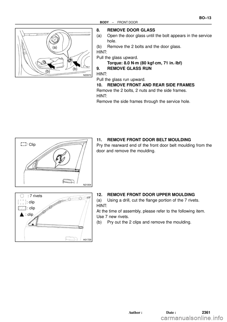
8. REMOVE DOOR GLASS
(a) Open the door glass until the bolt appears in the service
hole.
(b) Remove the 2 bolts and the door glass.
HINT:
Pull the glass upward.
Torque: 8.0 N´m (80 kgf´cm, 71 in.´lbf)
9. REMOVE GLASS RUN
HINT:
Pull the glass run upward.
10. REMOVE FRONT AND REAR SIDE FRAMES
Remove the 2 bolts, 2 nuts and the side frames.
HINT:
Remove the side frames through the service hole.
11. REMOVE FRONT DOOR BELT MOULDING
Pry the rearward end of the front door belt moulding from the
door and remove the moulding.
12. REMOVE FRONT DOOR UPPER MOULDING
(a) Using a drill, cut the flange portion of the 7 rivets.
HINT:
At the time of assembly, please refer to the following item.
Use 7 new rivets.
(b) Pry out the 2 clips and remove the moulding.
Page 861 of 4592
BO0L6±01
H01733
Door LockRear Door Upper
Moulding
Door Belt Moulding
Door Glass
Outside handle
Door Glass Run
Door Lock
Door Lock Striker
Rear Side Frame
Rear Door WeatherstripWindow Regulator
Inside Handle BezelInside HandleWindow
Regulator
Motor Child Protector
Lock Lever Cover
Snap Ring
Regulator
Handle Plate Door Trim Service Hole Cover Power Window
Switch Cover Door HingeDoor Hinge
Door Check w/o Power Door
Lock:
w/o Power Window:
: Specified torque
N´m (kgf´cm, ft´lbf)
3.5 (35, 31 in.´lbf)
5.5 (55, 49 in.´lbf)
5.5 (55, 49 in.´lbf)
23 (230, 17)
7.0 (70, 61 in.´lbf)
Door Lock Control Link
Door Lock Remote
Control Link
5.0 (50, 43 in.´lbf)
8.0 (80, 71 in.´lbf)
26 (260, 19)
8.0 (80, 71 in.´lbf)
30 (300, 22)
26 (260, 19)
± BODYREAR DOOR
BO±17
2365 Author�: Date�:
REAR DOOR
COMPONENTS


5.5 (55, 49 in")