Page 48 of 4592

(B)
± AIR CONDITIONINGCOMPRESSOR AND MAGNETIC CLUTCH
AC±47
2529 Author�: Date�:
INSTALLATION
1. 5S±FE engine models:
INSTALL COMPRESSOR
(a) Install the compressor with 3 bolts.")
AC0M9±02
N20259
(A)
(B)
± AIR CONDITIONINGCOMPRESSOR AND MAGNETIC CLUTCH
AC±47
2529 Author�: Date�:
INSTALLATION
1. 5S±FE engine models:
INSTALL COMPRESSOR
(a) Install the compressor with 3 bolts.
Torque: 25 N´m (250 kgf´cm, 18 ft´lbf)
(b) Connect the connector.
2. 1MZ±FE engine models:
INSTALL COMPRESSOR
(a) Install the compressor with 3 bolts.
Torque: 25 N´m (250 kgf´cm, 18 ft´lbf)
(b) Install the drive belt adjusting bar bracket with 2 bolts and
nut.
Torque:
Bolt (A): 25 N´m (250 kgf´cm, 18 ft´lbf)
Bolt (B): 18 N´m (185 kgf´cm, 13 ft´lbf)
Nut: 25 N´m (250 kgf´cm, 18 ft´lbf)
(c) Connect the connector.
3. 5S±FE engine models:
CONNECT DISCHARGE AND SUCTION HOSE
Connect the both hoses with the 2 bolts.
Torque: 10 N´m (100 kgf´cm, 7 ft´lbf)
NOTICE:
Hoses should be connected immediately after the caps
have been removed.
HINT:
Lubricate 2 new O±rings with compressor oil and install the
tubes.
4. 1MZ±FE engine models:
INSTALL GENERATOR
(a) Mount generator on the generator bracket with the pivot
bolt and adjusting lock bolt. Do not tighten the bolts yet.
(b) Connect the generator connector.
(c) Connect the generator wire with the nut.
Page 49 of 4592

AC±48
± AIR CONDITIONINGCOMPRESSOR AND MAGNETIC CLUTCH
2530 Author�: Date�:
5. 1MZ±FE engine models:
CONNECT DISCHARGE HOSE
Connect the discharge hose with the bolt.
Torque: 10 N´m (100 kgf´cm, 7 ft´lbf)
NOTICE:
Hoses should be connected immediately after the caps
have been removed.
HINT:
Lubricate a new O±ring with compressor oil and install the tube.
6. INSTALL SUCTION HOSE
(a) Install the suction hose and tighten the bolt and nut.
Torque:
Piping joint: 32 N´m (330 kgf´cm, 24 ft´lbf)
Block joint: 10 N´m (100 kgf´cm, 7 ft´lbf)
HINT:
Lubricate 2 new O±rings with compressor oil and install the
hose.
(b) Install the suction hose clamping bolt.
(c) Connect the wire harness clamp.
7. INSTALL AND CHECK DRIVE BELT
(See page AC±18, AC±16)
8. CONNECT NEGATIVE (±) TERMINAL CABLE TO BAT-
TERY
9. EVACUATE AIR FROM REFRIGERATION SYSTEM
AND CHARGE SYSTEM WITH REFRIGERANT
Specified amount: 800 ± 50 g (28.22 ± 1.76 oz.)
10. INSPECT FOR LEAKAGE OF REFRIGERANT
Using a gas leak detector, check for leakage of refrigerant.
If there is leakage, check the tightening torque at the joints.
11. INSPECT A/C OPERATION
Page 588 of 4592

4. Wire Harness±")
± BODY ELECTRICALBODY ELECTRICAL SYSTEM
BE±7
2227 Author�: Date�:
Seat Belt warning light does not light up.
1. Bulb
2. Seat Belt Buckle Switch
3. Integration Relay (I/P J/B No.1)
4. Wire Harness±
BE±47
BE±47
±
Discharge warning light does not light up.
1. IGN Fuse (I/P J/B No.1)
2. Bulb
3. Wire Harness
4. Generator (5S±FE)
(1MZ±FE)±
±
±
CH±1
CH±1
Light Failure warning light does not light up.
1. Bulb
2. Light Failure Sensor
3. Bulb Check Relay
4. Wire Harness
5. Taillight system±
BE±37
BE±47
±
BE±24
Brake warning light does not light up.
1. Bulb
2. Parking Brake Switch
3. Brake Fluid Level Warning Switch
4. Bulb Check Relay
5. Meter Circuit Plate
6. Wire Harness±
BE±47
BE±47
BE±47
BE±46
±
SRS Warning light does not light up.
1. ECU±B Fuse (E/G Room J/B No.2)
2. Bulb
3. Airbag Sensor Assembly
4. Meter Circuit Plate
5. Wire Harness±
±
DI±626
BE±46
±
Open Door warning light does not light up.
1. DOME Fuse (E/G Room J/B No.2)
2. Bulb
3. Door Courtesy Switch
4. Meter Circuit Plate
5. Wire Harness±
±
BE±32
BE±46
±
Washer Level warning light does not light up.
1. Bulb
2. Washer Fluid Level Warning Switch
3. Meter Circuit Plate
4. Wire Harness±
BE±47
BE±46
±
COMBINATION METER
INDICATOR LIGHTS:
SymptomSuspect AreaSee page
O/D OFF indicator light does not light up.
1. Bulb
2. O/D OFF Switch (A140E)
(A541E)
3. Meter Circuit Plate
4. Wire Harness±
DI±431
DI±487
BE±46
±
Cruise Control indicator light does not light up.
1. Bulb
2. Cruise Control ECU
3. Meter Circuit Plate
4. Wire Harness±
IN±31
BE±46
±
High beam indicator light does not light up.
1. Bulb
2. Meter Circuit Plate
3. Wire Harness
4. Headlight System±
BE±46
±
BE±22
Turn indicator light does not light up.
1. Bulb
2. Meter Circuit Plate
3. Wire Harness
4. Turn Signal and Hazard Warning System±
BE±46
±
BE±29
Page 597 of 4592
 Disconnect the negat")
N20133
101 65
N20134
101 65
N20135
Junction block side:
1 2 3 4 5 6 7 8 10 11 9 12
BE±16± BODY ELECTRICALIGNITION SWITCH AND KEY UNLOCK WARNING
SWITCH
2236 Author�: Date�:
(d) Disconnect the negative (±) lead from the battery to termi-
nal 6.
(e) Check that the buzzerr stops sounding.
(f) Connect the negative (±) lead from the battery to terminal
6.
(g) Disconnect the negative (±) lead from the battery to termi-
nal 5.
(h) Check that the buzzerr stops sounding.
If operation is not as specified, replace the relay.
6. INSPECT INTEGRATION RELAY (TYPE A) CIRCUIT
(a) Remove the relay from the junction block No.1 and in-
spect the connector on the junction block side.
Tester connectionConditionSpecified condition
2 ± Ground
4 ± GroundPassenger's door courtesy switch OFF (Door
closed)No continuity
2 ± Ground
4 ± GroundPassenger's door courtesy switch ON (Door
opened)Continuity
5 ± GroundKey unlock warning switch OFFNo continuity
5 ± GroundKey unlock warning switch ONContinuity
6 ± GroundDriver's door courtesy switch OFFNo continuity
6 ± GroundDriver's door courtesy switch ONContinuity
8 ± GroundBuckle switch OFF (Seat belt unfastened)No continuity
8 ± GroundBuckle switch ON (Seat belt fastened)Continuity
10 ± GroundConstantContinuity
1 ± GroundConstantBattery positive voltage
7 ± Ground
9 ± GroundIgnition switch LOCK or ACCNo voltage
7 ± Ground
9 ± GroundIgnition switch ONBattery positive voltage
Page 599 of 4592

N20137
Wire harness side:
Wire harness side:
20 14 13 1211 10 8 479
22 21 19 18 17 15 1656 123
23 24 25
1234
Connector ºAº
Connector ºBº
eh±25±1
h±4±1
BE±18± BODY ELECTRICALIGNITION SWITCH AND KEY UNLOCK WARNING
SWITCH
2238 Author�: Date�:
5 ± GroundKey unlock warning switch OFFNo continuity
5 ± GroundKey unlock warning switch ONContinuity
6 ± GroundDriver's door courtesy switch OFF (Door closed)No continuity
6 ± GroundDriver's door courtesy switch ON (Door opened)Continuity
8 ± GroundBuckle switch OFF (Seat belt unfastened)No continuity
8 ± GroundBuckle switch ON (Seat belt fastened)Continuity
10 ± GroundConstantContinuity
1 ± GroundConstantBattery positive voltage
7 ± Ground
9 ± GroundIgnition switch LOCK or ACCNo voltage
7 ± Ground
9 ± GroundIgnition switch ONBattery positive voltage
11 ± GroundIgnition switch LOCKNo voltage
11 ± GroundIgnition switch ACC or ONBattery positive voltage
(b) Disconnect the connector from the integration relay and
inspect the connectors on the wire harness side.
Tester connectionConditionSpecified condition
A3 ± GroundConstantContinuity
A5 ± GroundDriver's door unlock detection switch OFF (Door
locked)No continuity
A5 ± GroundDriver's door unlock detection switch ON (Door
unlocked)Continuity
A6 ± GroundPassenger's door courtesy switch OFF (Door
closed)No continuity
Page 601 of 4592

N20138
Wire harness side:
Wire harness side:
13 12 11 10 84
795
6 123
1234
Connector ºAº
Connector ºBº BE±20
± BODY ELECTRICALIGNITION SWITCH AND KEY UNLOCK WARNING
SWITCH
2240 Author�: Date�:
Tester connectionConditionSpecified condition
2 ± GroundAll door courtesy switches OFF (Except Driver's
Door/ Door closed)No continuity
2 ± GroundOne of the door courtesy switches ON (Except
Driver's Door/ Door opened)Continuity
4 ± GroundDoor courtesy switches except that of the driver's
door OFF (Door closed)No continuity
4 ± GroundOne of the door courtesy switches except that of
the driver's door ON (Door opened)Continuity
5 ± GroundKey unlock warning switch OFFNo continuity
5 ± GroundKey unlock warning switch ONContinuity
6 ± GroundDriver's door courtesy switch OFF (Door closed)No continuity
6 ± GroundDriver's door courtesy switch ON (Door opened)Continuity
8 ± GroundBuckle switch OFF (Seat belt unfastened)No continuity
8 ± GroundBuckle switch ON (Seat belt fastened)Continuity
10 ± GroundConstantContinuity
1 ± GroundConstantBattery positive voltage
7 ± Ground
9 ± GroundIgnition switch LOCK or ACCNo voltage
7 ± Ground
9 ± GroundIgnition switch ONBattery positive voltage
11 ± GroundIgnition switch LOCKNo voltage
11 ± GroundIgnition switch ACC or ONBattery positive voltage
(b) Disconnect the connector from the integration relay and
inspect the connectors on the wire harness side.
Page 626 of 4592
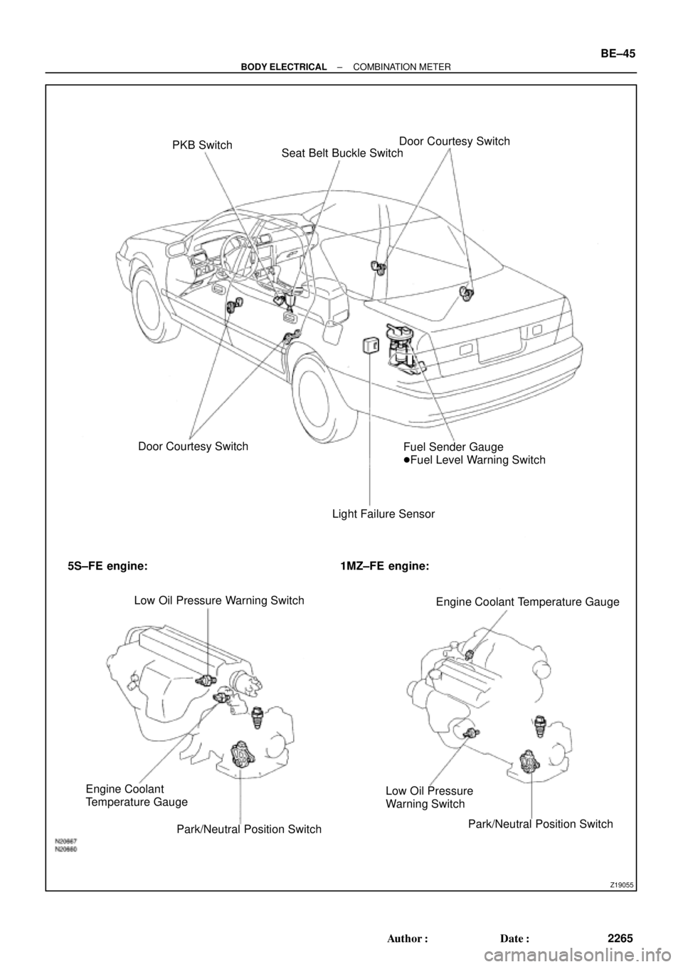
Z19055
PKB Switch
Seat Belt Buckle SwitchDoor Courtesy Switch
Door Courtesy Switch
Light Failure SensorFuel Sender Gauge
�Fuel Level Warning Switch
5S±FE engine: 1MZ±FE engine:
Low Oil Pressure Warning Switch
Engine Coolant Temperature Gauge
Engine Coolant
Temperature Gauge
Park/Neutral Position SwitchLow Oil Pressure
Warning Switch
Park/Neutral Position Switch
± BODY ELECTRICALCOMBINATION METER
BE±45
2265 Author�: Date�:
Page 627 of 4592

BE0AJ±03
Z18937
Connector ºAº Connector ºBº Connector ºCº
Connector ºAº
Connector ºBº
Connector ºCº
J±13±1±A J±16±1 J±13±1
1 2 3 4 5 6 7 8 9 10 11 12 1314 15 16 1 234 56 78 910111213 1 23456 78910111213
C7
C5
A2 B3
A1
C8
B15
C6
B6
A4
C4
B5
C10 B14
A13
B2
C1
B1
C9
A6
A11
A7
A10
A8
A9
C13
B8
B11
B12A5
C11
B4
B16 C2
A12
A3
B7
C3
C12
B9
B10
B13 F
E
T
S
ODOMETER
Fuel Level Warning
Seat Belt Warning
ABS Warning
Low Oil Pressure Warning
Cruise Control Indicator
Malfunction Indicator
O/D OFF Indicator
Light Failure Warning
Brake Warning
SLIP Indicator
TRAC Indicator
Washer Level Warning
Discharge Warning
Right Turn Indicator
Left Turn Indicator
Security Indicator
L
2
D
N
R
P
Illumination
Hi±Beam Indicator
Open Door Warning
SRS Warning
: Fuel Gauge
: Engine Coolant Temperature Gauge
: Tachometer
: Speedometer
No.
A
B
C1
2
3
4
5
6
7 8
9
10
11
12 13
14
15
16
2 3
4
5
6
7 8
9
10
11 12
131
2
3
4 5
6
7
8
9
10
11
12
13
F
E
T
SEngine coolant temperature sender gauge
Ground
Light failure sensor
Integration relay
Traction ECU
Park/neutral position switch (A/T)
O/D OFF switch (A/T)
IGN fuse
Turn signal switch
ST relay
Fuel sender gauge
Generator
Oil pressure switch
Fuel sender gauge
Parking brake switch and brake fluid level warning switch
Headlight dimmer switch
Headlight dimmer switch
Door courtesy switch
DOME fuse
ECU±B fuse
Airbag sensor assembly
ECM
No.1 Vehicle speed sensor Ground
Turn signal switch ECM
Traction ECU
ABS ECU
Ground No.1 Vehicle speed sensor
GAUGE fuse
Igniter
Security ECU
Cruise control ECU
Washer fluid level warning switch
Light control rheostat
TAIL fuse Park/neutral position switch (A/T) Park/neutral position switch (A/T) Park/neutral position switch (A/T) Park/neutral position switch (A/T)
Park/neutral position switch (A/T)Wire Harness Side
Bulb Check
Relay
N20107 N201081
BE±46
± BODY ELECTRICALCOMBINATION METER
2266 Author�: Date�:
CIRCUIT