Page 633 of 4592

N20217
OFF
ONOhmmeter
Z05732
Warning Light
Ignition
Switch
Battery
1
BE0044
Warning Light
Ignition
Switch
Battery
Z16167
1
2 OFF
ON
N02354
1
2OFF
ON BE±52
± BODY ELECTRICALCOMBINATION METER
2272 Author�: Date�:
18. INSPECT WASHER FLUID LEVEL WARNING SWITCH
(a) Check that no continuity exists between terminals with the
switch OFF (float up).
(b) Check that continuity exists between terminals with the
switch ON (float down).
If operation is not as specified, replace the switch.
19. INSPECT OPEN DOOR WARNING LIGHT
Disconnect the connector from the door courtesy switch and
ground terminal 1 on the wire harness side, and check that the
warning light lights up.
If the warning light does not light up, inspect the bulb or wire har-
ness.
20. INSPECT SEAT BELT WARNING LIGHT
(a) Remove the integration relay from the instrument panel
junction block.
(b) Ground terminal 2 on the integration relay with the con-
nectors still connected.
(c) Turn the ignition switch ON and check that the warning
light lights up.
If the warning light does not light up, inspect the bulb or wire har-
ness.
21. w/o Power seat:
INSPECT BUCKLE SWITCH CONTINUITY
(a) Check that continuity exists between the terminals on the
switch side connector with the switch ON (belt fastened).
(b) Check that no continuity exists between the terminals on
the switch side connector with the switch OFF (belt unfas-
tened).
If operation is not as specified, replace the seat belt inner belt.
22. w/ Power seat:
INSPECT BUCKLE SWITCH CONTINUITY
(a) Check that continuity exists between terminals 1 and 2 on
the switch side connector with the switch ON (belt fas-
tened).
(b) Check that no continuity exists between terminals 1 and
2 on the switch side connector with the switch OFF (belt
unfastened).
If operation is not as specified, replace the seat belt inner belt.
Page 634 of 4592
N20219
Type A:
Type B and C:1
7
9
10
1
7
910
N20220
Type A:
Type B and C:1
7
9
10
1
7910 88
± BODY ELECTRICALCOMBINATION METER
BE±53
2273 Author�: Date�:
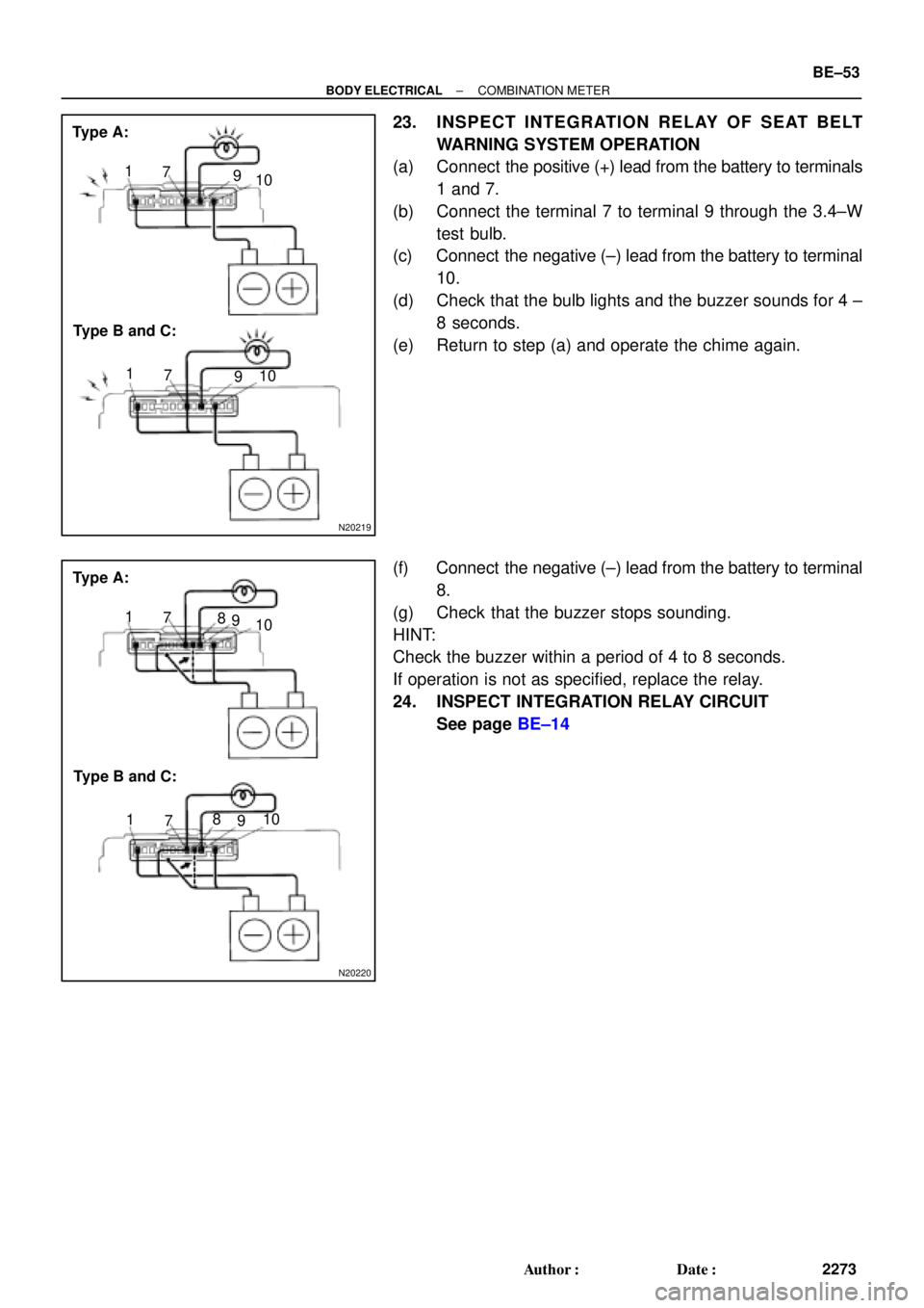
23. INSPECT INTEGRATION RELAY OF SEAT BELT
WARNING SYSTEM OPERATION
(a) Connect the positive (+) lead from the battery to terminals
1 and 7.
(b) Connect the terminal 7 to terminal 9 through the 3.4±W
test bulb.
(c) Connect the negative (±) lead from the battery to terminal
10.
(d) Check that the bulb lights and the buzzer sounds for 4 ±
8 seconds.
(e) Return to step (a) and operate the chime again.
(f) Connect the negative (±) lead from the battery to terminal
8.
(g) Check that the buzzer stops sounding.
HINT:
Check the buzzer within a period of 4 to 8 seconds.
If operation is not as specified, replace the relay.
24. INSPECT INTEGRATION RELAY CIRCUIT
See page BE±14
Page 712 of 4592
I08448
PKB Switch
Seat Belt Buckle SwitchDoor Courtesy Switch
Door Courtesy Switch
Light Failure Sensor
Low Oil Pressure Warning Switch
Engine Coolant Temperature
Sender Gauge
Park/Neutral Position Switch
± BODY ELECTRICALCOMBINATION METER
BE±3
535 Author�: Date�:
Page 713 of 4592

BE0AJ±04
Z18937
Connector ºAº Connector ºBº Connector ºCº
Connector ºAº
Connector ºBº
Connector ºCº
J±13±1±A J±16±1 J±13±1
1 2 3 4 5 6 7 8 9 10 11 12 1314 15 16 1 234 56 78 910111213 1 23456 78910111213
C7
C5
A2 B3
A1
C8
B15
C6
B6
A4
C4
B5
C10 B14
A13
B2
C1
B1
C9
A6
A11
A7
A10
A8
A9
C13
B8
B11
B12A5
C11
B4
B16 C2
A12
A3
B7
C3
C12
B9
B10
B13 F
E
T
S
ODOMETER
Fuel Level Warning
Seat Belt Warning
ABS Warning
Low Oil Pressure Warning
Cruise Control Indicator
Malfunction Indicator
O/D OFF Indicator
Light Failure Warning
Brake Warning
SLIP Indicator
TRAC Indicator
Washer Level Warning
Discharge Warning
Right Turn Indicator
Left Turn Indicator
Security Indicator
L
2
D
N
R
P
Illumination
Hi±Beam Indicator
Open Door Warning
SRS Warning
: Fuel Gauge
: Engine Coolant Temperature Sender Gauge
: Tachometer
: Speedometer
No.
A
B
C1
2
3
4
5
6
7 8
9
10
11
12 13
14
15
16
2 3
4
5
6
7 8
9
10
11 12
131
2
3
4 5
6
7
8
9
10
11
12
13
F
E
T
SEngine coolant temperature sender gauge
Ground
Light failure sensor
Integration relay
Traction ECU
Park/neutral position switch (A/T)
O/D OFF switch (A/T)
IGN fuse
Turn signal switch
ST relay
ECM
Generator
Oil pressure switch
ECM
Parking brake switch and brake fluid level warning switch
Headlight dimmer switch
Headlight dimmer switch
Door courtesy switch
DOME fuse
ECU±B fuse
Airbag sensor assembly
ECM
No.1 Vehicle speed sensor Ground
Turn signal switch ECM
Traction ECU
ABS ECU
Ground No.1 Vehicle speed sensor
GAUGE fuse
Igniter
Security ECU
Cruise control ECU
Washer fluid level warning switch
Light control rheostat
TAIL fuse Park/neutral position switch (A/T) Park/neutral position switch (A/T) Park/neutral position switch (A/T) Park/neutral position switch (A/T)
Park/neutral position switch (A/T)Wire Harness Side
Bulb Check
Relay
N20107 N201081
BE±4
± BODY ELECTRICALCOMBINATION METER
CIRCUIT
Page 723 of 4592

4. Wire Harness±")
± BODY ELECTRICALBODY ELECTRICAL SYSTEM
BE±7
2227 Author�: Date�:
Seat Belt warning light does not light up.
1. Bulb
2. Seat Belt Buckle Switch
3. Integration Relay (I/P J/B No.1)
4. Wire Harness±
BE±47
BE±47
±
Discharge warning light does not light up.
1. IGN Fuse (I/P J/B No.1)
2. Bulb
3. Wire Harness
4. Generator (5S±FE)
(1MZ±FE)±
±
±
CH±1
CH±1
Light Failure warning light does not light up.
1. Bulb
2. Light Failure Sensor
3. Bulb Check Relay
4. Wire Harness
5. Taillight system±
BE±37
BE±47
±
BE±24
Brake warning light does not light up.
1. Bulb
2. Parking Brake Switch
3. Brake Fluid Level Warning Switch
4. Bulb Check Relay
5. Meter Circuit Plate
6. Wire Harness±
BE±47
BE±47
BE±47
BE±46
±
SRS Warning light does not light up.
1. ECU±B Fuse (E/G Room J/B No.2)
2. Bulb
3. Airbag Sensor Assembly
4. Meter Circuit Plate
5. Wire Harness±
±
DI±626
BE±46
±
Open Door warning light does not light up.
1. DOME Fuse (E/G Room J/B No.2)
2. Bulb
3. Door Courtesy Switch
4. Meter Circuit Plate
5. Wire Harness±
±
BE±32
BE±46
±
Washer Level warning light does not light up.
1. Bulb
2. Washer Fluid Level Warning Switch
3. Meter Circuit Plate
4. Wire Harness±
BE±47
BE±46
±
COMBINATION METER
INDICATOR LIGHTS:
SymptomSuspect AreaSee page
O/D OFF indicator light does not light up.
1. Bulb
2. O/D OFF Switch (A140E)
(A541E)
3. Meter Circuit Plate
4. Wire Harness±
DI±431
DI±487
BE±46
±
Cruise Control indicator light does not light up.
1. Bulb
2. Cruise Control ECU
3. Meter Circuit Plate
4. Wire Harness±
IN±31
BE±46
±
High beam indicator light does not light up.
1. Bulb
2. Meter Circuit Plate
3. Wire Harness
4. Headlight System±
BE±46
±
BE±22
Turn indicator light does not light up.
1. Bulb
2. Meter Circuit Plate
3. Wire Harness
4. Turn Signal and Hazard Warning System±
BE±46
±
BE±29
Page 732 of 4592
 Disconnect the negat")
N20133
101 65
N20134
101 65
N20135
Junction block side:
1 2 3 4 5 6 7 8 10 11 9 12
BE±16± BODY ELECTRICALIGNITION SWITCH AND KEY UNLOCK WARNING
SWITCH
2236 Author�: Date�:
(d) Disconnect the negative (±) lead from the battery to termi-
nal 6.
(e) Check that the buzzerr stops sounding.
(f) Connect the negative (±) lead from the battery to terminal
6.
(g) Disconnect the negative (±) lead from the battery to termi-
nal 5.
(h) Check that the buzzerr stops sounding.
If operation is not as specified, replace the relay.
6. INSPECT INTEGRATION RELAY (TYPE A) CIRCUIT
(a) Remove the relay from the junction block No.1 and in-
spect the connector on the junction block side.
Tester connectionConditionSpecified condition
2 ± Ground
4 ± GroundPassenger's door courtesy switch OFF (Door
closed)No continuity
2 ± Ground
4 ± GroundPassenger's door courtesy switch ON (Door
opened)Continuity
5 ± GroundKey unlock warning switch OFFNo continuity
5 ± GroundKey unlock warning switch ONContinuity
6 ± GroundDriver's door courtesy switch OFFNo continuity
6 ± GroundDriver's door courtesy switch ONContinuity
8 ± GroundBuckle switch OFF (Seat belt unfastened)No continuity
8 ± GroundBuckle switch ON (Seat belt fastened)Continuity
10 ± GroundConstantContinuity
1 ± GroundConstantBattery positive voltage
7 ± Ground
9 ± GroundIgnition switch LOCK or ACCNo voltage
7 ± Ground
9 ± GroundIgnition switch ONBattery positive voltage
Page 734 of 4592

N20137
Wire harness side:
Wire harness side:
20 14 13 1211 10 8 479
22 21 19 18 17 15 1656 123
23 24 25
1234
Connector ºAº
Connector ºBº
eh±25±1
h±4±1
BE±18± BODY ELECTRICALIGNITION SWITCH AND KEY UNLOCK WARNING
SWITCH
2238 Author�: Date�:
5 ± GroundKey unlock warning switch OFFNo continuity
5 ± GroundKey unlock warning switch ONContinuity
6 ± GroundDriver's door courtesy switch OFF (Door closed)No continuity
6 ± GroundDriver's door courtesy switch ON (Door opened)Continuity
8 ± GroundBuckle switch OFF (Seat belt unfastened)No continuity
8 ± GroundBuckle switch ON (Seat belt fastened)Continuity
10 ± GroundConstantContinuity
1 ± GroundConstantBattery positive voltage
7 ± Ground
9 ± GroundIgnition switch LOCK or ACCNo voltage
7 ± Ground
9 ± GroundIgnition switch ONBattery positive voltage
11 ± GroundIgnition switch LOCKNo voltage
11 ± GroundIgnition switch ACC or ONBattery positive voltage
(b) Disconnect the connector from the integration relay and
inspect the connectors on the wire harness side.
Tester connectionConditionSpecified condition
A3 ± GroundConstantContinuity
A5 ± GroundDriver's door unlock detection switch OFF (Door
locked)No continuity
A5 ± GroundDriver's door unlock detection switch ON (Door
unlocked)Continuity
A6 ± GroundPassenger's door courtesy switch OFF (Door
closed)No continuity
Page 736 of 4592

N20138
Wire harness side:
Wire harness side:
13 12 11 10 84
795
6 123
1234
Connector ºAº
Connector ºBº BE±20
± BODY ELECTRICALIGNITION SWITCH AND KEY UNLOCK WARNING
SWITCH
2240 Author�: Date�:
Tester connectionConditionSpecified condition
2 ± GroundAll door courtesy switches OFF (Except Driver's
Door/ Door closed)No continuity
2 ± GroundOne of the door courtesy switches ON (Except
Driver's Door/ Door opened)Continuity
4 ± GroundDoor courtesy switches except that of the driver's
door OFF (Door closed)No continuity
4 ± GroundOne of the door courtesy switches except that of
the driver's door ON (Door opened)Continuity
5 ± GroundKey unlock warning switch OFFNo continuity
5 ± GroundKey unlock warning switch ONContinuity
6 ± GroundDriver's door courtesy switch OFF (Door closed)No continuity
6 ± GroundDriver's door courtesy switch ON (Door opened)Continuity
8 ± GroundBuckle switch OFF (Seat belt unfastened)No continuity
8 ± GroundBuckle switch ON (Seat belt fastened)Continuity
10 ± GroundConstantContinuity
1 ± GroundConstantBattery positive voltage
7 ± Ground
9 ± GroundIgnition switch LOCK or ACCNo voltage
7 ± Ground
9 ± GroundIgnition switch ONBattery positive voltage
11 ± GroundIgnition switch LOCKNo voltage
11 ± GroundIgnition switch ACC or ONBattery positive voltage
(b) Disconnect the connector from the integration relay and
inspect the connectors on the wire harness side.