Page 1346 of 4592
A00472
ON
FE
G
FE
G
VSV is ON
VSV is OFF
DI±134
± DIAGNOSTICSENGINE (5S±FE)
369 Author�: Date�:
10 Check the VSV for vapor pressure sensor.
PREPARATION:
(a) Connect the TOYOTA hand±held tester to the DLC3.
(b) Turn the ignition switch ON and push the OBD II scan tool
or TOYOTA hand±held tester main switch ON.
(c) Select the ACTIVE TEST mode on the TOYOTA hand±
held tester.
CHECK:
Check the VSV operation when it is operated by TOYOTA
hand±held tester.
OK:
(1) VSV is ON:
Air from port E is flowing out through port F.
(2) VSV is OFF:
Air from port E is flowing out through port G.
OK Go to step 13.
NG
11 Check operation of VSV for vapor pressure sensor (See page SF±47).
OK Gp to step 12.
NG
Replace VSV charcoal canister, and then clean the vacuum hoses between charcoal canister and
VSV for vapor pressure sensor, and VSV for vapor pressure sensor and vapor pressure sensor.
Page 1351 of 4592
A03019A03423
EVPON
ON
OFF
E
E
F
VSV is ON
VSV is OFF w/o Immobiliser
w/ Immobiliser
ON
OFF
FE EVP
± DIAGNOSTICSENGINE (5S±FE)
DI±139
374 Author�: Date�:
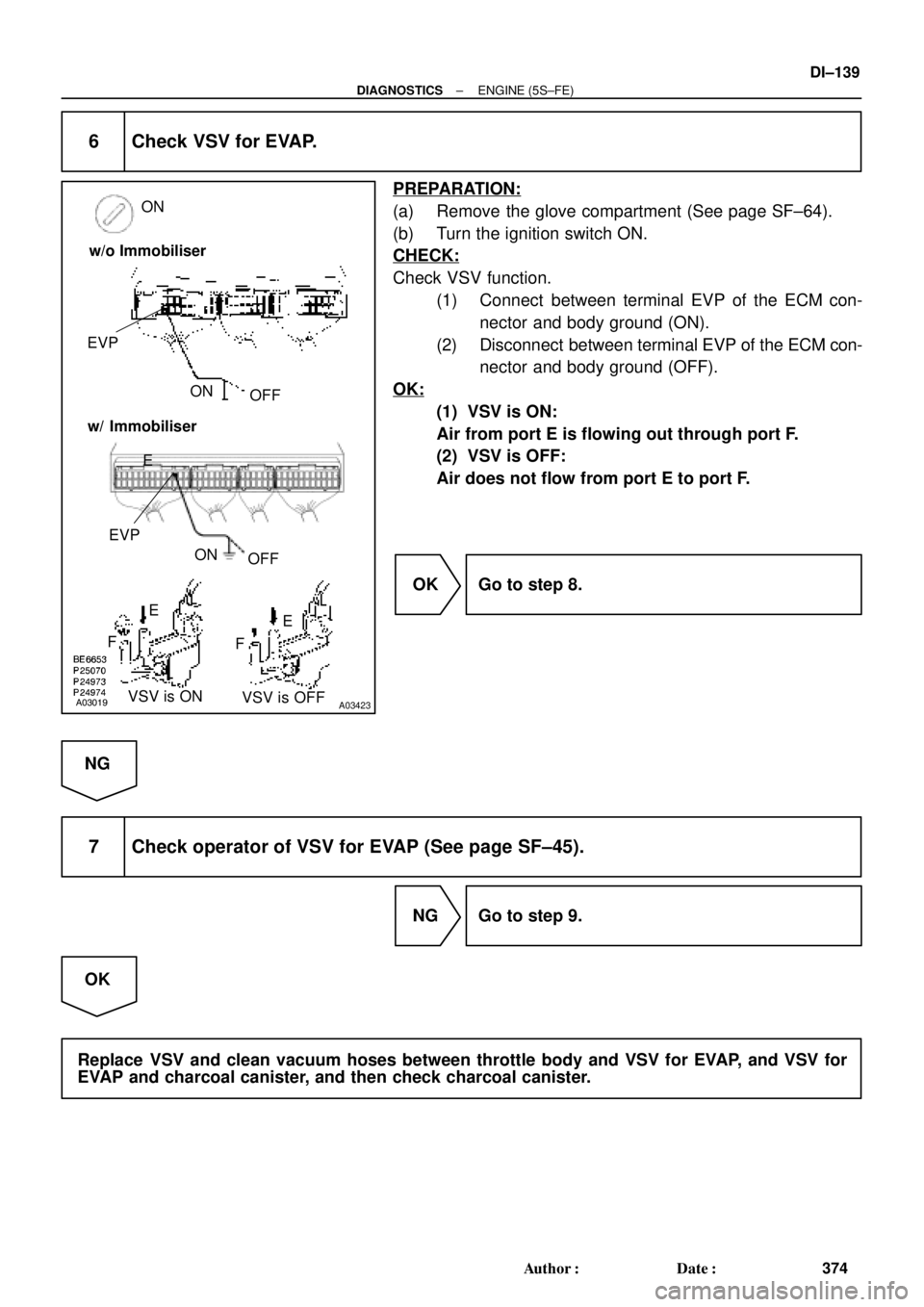
6 Check VSV for EVAP.
PREPARATION:
(a) Remove the glove compartment (See page SF±64).
(b) Turn the ignition switch ON.
CHECK:
Check VSV function.
(1) Connect between terminal EVP of the ECM con-
nector and body ground (ON).
(2) Disconnect between terminal EVP of the ECM con-
nector and body ground (OFF).
OK:
(1) VSV is ON:
Air from port E is flowing out through port F.
(2) VSV is OFF:
Air does not flow from port E to port F.
OK Go to step 8.
NG
7 Check operator of VSV for EVAP (See page SF±45).
NG Go to step 9.
OK
Replace VSV and clean vacuum hoses between throttle body and VSV for EVAP, and VSV for
EVAP and charcoal canister, and then check charcoal canister.
Page 1352 of 4592
A03020A03424
ON
OFF
ONTPC
E
G
FFE
G
VSV is ON
VSV is OFF OFFONTPC
w/o Immobiliser
w/ Immobiliser
DI±140
± DIAGNOSTICSENGINE (5S±FE)
375 Author�: Date�:
8 Check for open and short in harness and connector between EFI main relay
(Marking: EFI) and VSV for EVAP, and VSV for EVAP and ECM (See page IN±31)
NG Repair or replace harness or connector.
OK
Check and replace ECM (See page IN±31).
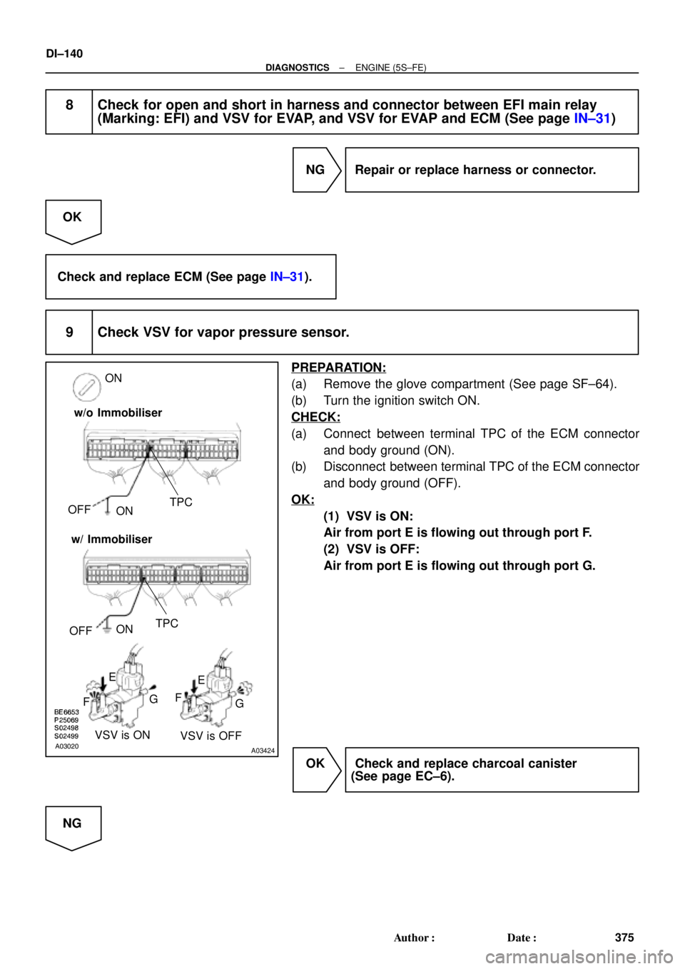
9 Check VSV for vapor pressure sensor.
PREPARATION:
(a) Remove the glove compartment (See page SF±64).
(b) Turn the ignition switch ON.
CHECK:
(a) Connect between terminal TPC of the ECM connector
and body ground (ON).
(b) Disconnect between terminal TPC of the ECM connector
and body ground (OFF).
OK:
(1) VSV is ON:
Air from port E is flowing out through port F.
(2) VSV is OFF:
Air from port E is flowing out through port G.
OK Check and replace charcoal canister
(See page EC±6).
NG
Page 1359 of 4592
A03021
A03425
ON
SP1
(+)
SP1
(+)
w/o Immobiliser
w/ Immobiliser
AT7809
4.5 ~ 5.5 V
0
Turn the wheel
± DIAGNOSTICSENGINE (5S±FE)
DI±147
382 Author�: Date�:
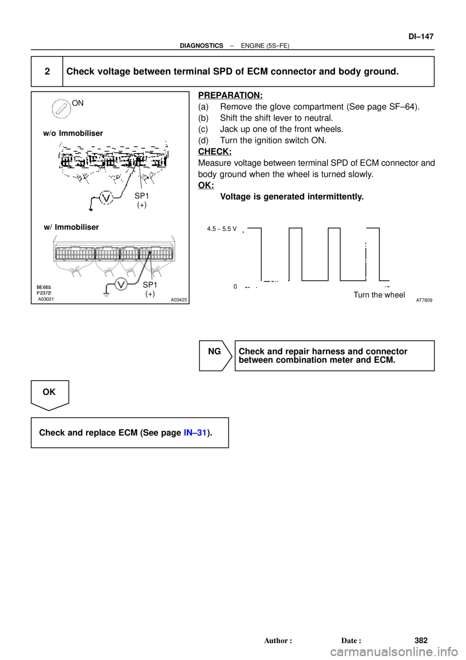
2 Check voltage between terminal SPD of ECM connector and body ground.
PREPARATION:
(a) Remove the glove compartment (See page SF±64).
(b) Shift the shift lever to neutral.
(c) Jack up one of the front wheels.
(d) Turn the ignition switch ON.
CHECK:
Measure voltage between terminal SPD of ECM connector and
body ground when the wheel is turned slowly.
OK:
Voltage is generated intermittently.
NG Check and repair harness and connector
between combination meter and ECM.
OK
Check and replace ECM (See page IN±31).
Page 1360 of 4592

P01559
Throttle Valve
To Cylinder ECM Signal From
Air
Cleaner
Valve
IAC Valve
Intake Air
Chamber
A07553
B±Y 9
2B±Y B±Y
II3J19
J/CIAC ValveECM
1
3 2
B
EFI
5
1 Engine Room J/B No.2
42
2J
W±B
B
ISCO
E01
E01 ISCC10
9W
B±OE9
E9
1
2A
2K
EFI Relay
EB
From
BatteryB
*1: w/o Immobiliser
*2: w/ Immobiliser(*1) (*2)
E97
E96
(*2) (*1)
E107MREL2FB±W B±W
II4
(*2)
7
6(*2) (*2)
3
B±R
(*1)From
Ignition SW DI±148
± DIAGNOSTICSENGINE (5S±FE)
383 Author�: Date�:
DTC P0505 Idle Control System Malfunction
CIRCUIT DESCRIPTION
The rotary solenoid type IAC valve is located on the throttle
body and intake air bypassing the throttle valve is directed to
the IAC valve through a passage.
In this way the intake air volume bypassing the throttle valve is
regulated, controlling the engine speed.
The ECM operates only the IAC valve to perform idle±up and
provide feedback for the target idling speed.
DTC No.DTC Detecting ConditionTrouble AreaTrouble Area
P0505Idle speed continues to vary greatly from the target speed
(2 trip detection logic)
�IAC valve is stuck or closed
�Open or short in IAC valve circuit
�Open or short in A/C switch circuit
�Air intake (hose loose)
�ECM
WIRING DIAGRAM
DI01C±05
Page 1362 of 4592
A00416
A03022A03426
E9 Connector
RSC(+) RSO(+)
E9 Connector
RSO(+)
RSC(+) w/o Immobiliser
w/ Immobiliser
DI±150
± DIAGNOSTICSENGINE (5S±FE)
385 Author�: Date�:
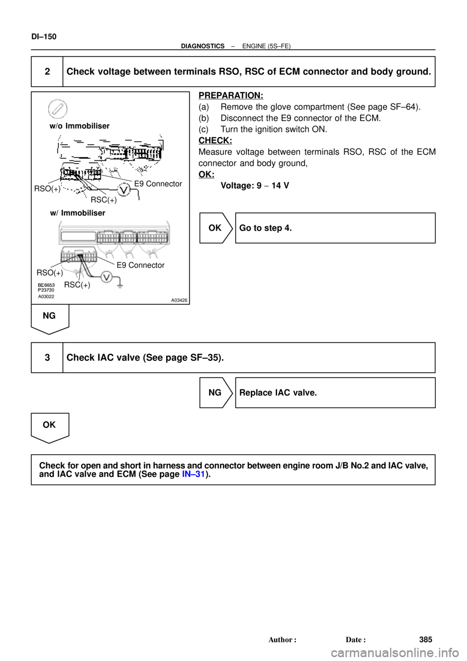
2 Check voltage between terminals RSO, RSC of ECM connector and body ground.
PREPARATION:
(a) Remove the glove compartment (See page SF±64).
(b) Disconnect the E9 connector of the ECM.
(c) Turn the ignition switch ON.
CHECK:
Measure voltage between terminals RSO, RSC of the ECM
connector and body ground,
OK:
Voltage: 9 ~ 14 V
OK Go to step 4.
NG
3 Check IAC valve (See page SF±35).
NG Replace IAC valve.
OK
Check for open and short in harness and connector between engine room J/B No.2 and IAC valve,
and IAC valve and ECM (See page IN±31).
Page 1365 of 4592

Idling
IG SW OFF
3 ~ 5 min.
Time
(1)(2)(4)
(3)
± DIAGNOSTICSENGINE (5S±FE)
DI±153
388 Author�: Date�:
CONFIRMATION DRIVING PATTERN
(1) Connect the")
A00364
Vehicle Speed
60 ~ 120 km/h
(38 ~ 75 mph)
Idling
IG SW OFF
3 ~ 5 min.
Time
(1)(2)(4)
(3)
± DIAGNOSTICSENGINE (5S±FE)
DI±153
388 Author�: Date�:
CONFIRMATION DRIVING PATTERN
(1) Connect the TOYOTA hand±held tester to the DLC3.
(2) Switch the TOYOTA hand±held tester from normal mode to check mode (See page DI±3).
(3) Start the engine and warm it up with all accessory switches OFF.
(4) Drive the vehicle at 60 ~ 120 km/h (38 ~ 75 mph) and engine speed at 1,600 ~ 3,200 rpm for 3
~ 5 min.
HINT:
If a malfunction exists, the MIL will light up during step (4).
NOTICE:
If the conditions in this test are not strictly followed, detection of the malfunction will not be possible.
If you do not have a TOYOTA hand±held tester, turn the ignition switch OFF after performing steps
(3) and (4), then perform steps (3) and (4) again.
INSPECTION PROCEDURE
HINT:
Read freeze frame data using TOYOTA hand±held tester or OBD II scan tool. Because freeze frame records
the engine conditions when the malfunction is detected, when troubleshooting it is useful for determining
whether the vehicle was running or stopped, the engine warmed up or not, the air±fuel ratio lean or rich, etc.
at the time of the malfunction.
1 Are there any other codes (besides DTC P1130) being output?
YES Go to relevant DTC chart.
NO
Page 1373 of 4592
 ON
± DIAGNOSTICSENGINE (5S±FE)
DI±161
396 Author�: Date�:
DTC P1135 A/F Sensor Heater Circuit Malfunction
(Only for California Spec.)
CIRCUIT DESCRIPTION
Refer to DTC P0125 (Insuffi")
A00430
HTAF (+) ON
± DIAGNOSTICSENGINE (5S±FE)
DI±161
396 Author�: Date�:
DTC P1135 A/F Sensor Heater Circuit Malfunction
(Only for California Spec.)
CIRCUIT DESCRIPTION
Refer to DTC P0125 (Insufficient Coolant Temp. for Closed Loop Fuel Control (Only for California Spec.))
on page DI±61.
DTC No.DTC Detecting ConditionTrouble Area
P1135
When heater operates, heater current exceeds 8 A
(2 trip detection logic)�Open or short in heater circuit of A/F sensor
A/F h tP1135Heater current of 0.25 A or less when heater operates
(2 trip detection logic)�A/F sensor heater
�ECM
WIRING DIAGRAM
Refer to DTC P0125 (Insufficient Coolant Temp. for Closed Loop Fuel Control (Only for California Spec.))
on page DI±61.
INSPECTION PROCEDURE
HINT:
Read freeze frame data using TOYOTA hand±held tester or OBD II scan tool. Because freeze frame records
the engine conditions when the malfunction is detected, when troubleshooting it is useful for determining
whether the vehicle was running or stopped, the engine warmed up or not, the air±fuel ratio lean or rich, etc.
at the time of the malfunction.
1 Check voltage between terminal HTAF of ECM connector and body ground.
PREPARATION:
(a) Remove the glove compartment (See page SF±64).
(b) Turn the ignition switch ON.
CHECK:
Measure voltage between terminals HTAF of the ECM connec-
tor and body ground.
OK:
Voltage: 9 ~ 14 V
OK Check and replace ECM (See page IN±31).
NG
DI01F±05