Page 1288 of 4592
A03014A03415
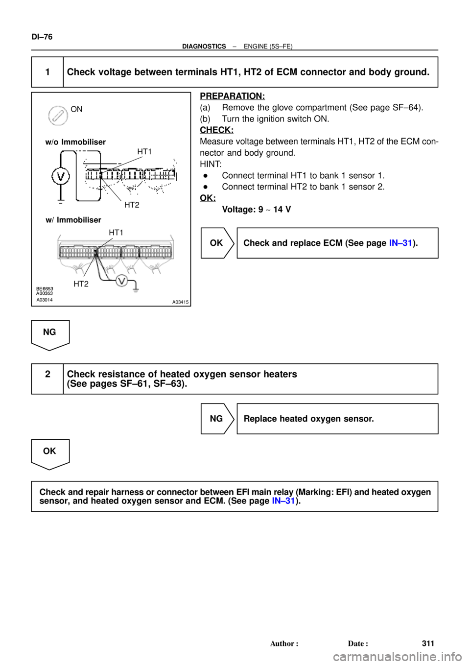
ON
HT1
HT2
w/o Immobiliser
w/ Immobiliser
HT1
HT2
DI±76
± DIAGNOSTICSENGINE (5S±FE)
311 Author�: Date�:
1 Check voltage between terminals HT1, HT2 of ECM connector and body ground.
PREPARATION:
(a) Remove the glove compartment (See page SF±64).
(b) Turn the ignition switch ON.
CHECK:
Measure voltage between terminals HT1, HT2 of the ECM con-
nector and body ground.
HINT:
�Connect terminal HT1 to bank 1 sensor 1.
�Connect terminal HT2 to bank 1 sensor 2.
OK:
Voltage: 9 ~ 14 V
OK Check and replace ECM (See page IN±31).
NG
2 Check resistance of heated oxygen sensor heaters
(See pages SF±61, SF±63).
NG Replace heated oxygen sensor.
OK
Check and repair harness or connector between EFI main relay (Marking: EFI) and heated oxygen
sensor, and heated oxygen sensor and ECM. (See page IN±31).
Page 1292 of 4592
DI±80
± DIAGNOSTICSENGINE (5S±FE)
315 Author�: Date�: �
OBD II scan tool (excluding TOYOTA hand±held tester) displays the one fifth of the A/F sensor output
voltage which is displayed on the TOYOTA hand±held tester.
INSPECTION PROCEDURE
HINT:
Read freeze frame data using TOYOTA hand±held tester or OBD II scan tool. Because freeze frame records
the engine conditions when the malfunction is detected, when troubleshooting it is useful for determining
whether the vehicle was running or stopped, the engine warmed up or not, the airÅfuel ratio lean or rich, etc.
at the time of the malfunction.
1 Check air induction system (See page SF±1).
NG Repair or replace.
OK
2 Check injector injection (See page SF±23).
NG Replace injector.
OK
3 Check manifold absolute pressure sensor and engine coolant temp. sensor
(See pages SF±53 and SF±49).
NG Repair or replace.
OK
4 Check for spark and ignition (See page IG±1).
NG Repair or replace.
OK
Page 1297 of 4592
± DIAGNOSTICSENGINE (5S±FE)
DI±85
320 Author�: Date�:
INSPECTION PROCEDURE
HINT:
Read freeze frame data using TOYOTA hand±held tester or OBD II scan tool. Because freeze frame records
the engine conditions when the malfunction is detected, when troubleshooting it is useful for determining
whether the vehicle was running or stopped, the engine warmed up or not, the air±fuel ratio lean or rich, etc.
at the time of the malfunction.
1 Check air induction system (See page SF±1).
NG Repair or replace.
OK
2 Check injector injection (See page SF±23).
NG Replace injector.
OK
3 Check manifold absolute pressure sensor and engine coolant temp. sensor
(See pages SF±53 and SF±49).
NG Repair or replace.
OK
4 Check for spark and ignition (See page IG±1).
NG Repair or replace.
OK
Page 1301 of 4592

DI±89
324 Author�: Date�:
DTC P0300 Random/Multiple Cylinder Misfire Detected
DTC P0301 Cylinder 1 Misfire Detected
DTC P0302 Cylinder 2 Misfire Detected
DTC P0303 Cylin")
± DIAGNOSTICSENGINE (5S±FE)
DI±89
324 Author�: Date�:
DTC P0300 Random/Multiple Cylinder Misfire Detected
DTC P0301 Cylinder 1 Misfire Detected
DTC P0302 Cylinder 2 Misfire Detected
DTC P0303 Cylinder 3 Misfire Detected
DTC P0304 Cylinder 4 Misfire Detected
CIRCUIT DESCRIPTION
Misfire: The ECM uses the crankshaft position sensor and camshaft position sensor to monitor changes in
the crankshaft rotation for each cylinder.
The ECM counts the number of times the engine speed change rate indicates that misfire has occurred. And
when the misfire rate equals or exceeds the count indicating that the engine condition has deteriorated, the
MIL lights up.
If the misfire rate is high enough and the driving conditions will cause catalyst overheating, the MIL blinks
when misfiring occurs.
DTC No.DTC Detecting ConditionTrouble Area
P0300Mi fi i f d li d i d t t d d i ti l
�Ignition system
�Injector
�Fuel line pressure
�EGR
P0300
P0301
P0302
P0303
P0304
Misfiring of random cylinders is detected during any particular
200 or 1,000 revolutions
For any particular 200 revolutions for engine, misfiring is de-
tected which can cause catalyst overheating
(This causes MIL to blink)
�EGR
�Compression pressure
�Valve clearance not to specification
�Valve timing
�Manifold absolute pressure sensor
P0304(This causes MIL to blink)�Manifold absolute ressure sensor
�Engine coolant temp. sensor
�Open or short in engine wire
�Connector connection
�ECM
HINT:
When the 2 or more codes for a misfiring cylinder are recorded repeatedly but no random misfire code is
recorded, it indicates that the misfires were detected and recorded at different times.
DI011±07
Page 1303 of 4592

DI±91
326 Author�: Date�:
CONFIRMATION DRIVING PATTERN
(1) Connect the TOYOTA hand±held tester or OBD II scan tool.
(2) Record DTC and the freeze frame data.
(3) Use th")
± DIAGNOSTICSENGINE (5S±FE)
DI±91
326 Author�: Date�:
CONFIRMATION DRIVING PATTERN
(1) Connect the TOYOTA hand±held tester or OBD II scan tool.
(2) Record DTC and the freeze frame data.
(3) Use the TOYOTA hand±held tester to set to Check Mode. (See page DI±3)
(4) Drive the vehicle several times with the engine speed, load and its surrounding range shown with
ENGINE SPD, CALC LOAD in the freeze frame data or MISFIRE RPM, MISFIRE LOAD in the data list.
If you have no TOYOTA hand±held tester, turn the ignition switch OFF after the symptom is simulated
the first time. Then repeat the simulation process again.
HINT:
In order to memorize DTC of misfire, it is necessary to drive around MISFIRE RPM, MISFIRE LOAD in the
data list for the following period of time.
Engine SpeedTime
Idling3 minutes 30 seconds or more
1000 rpm3 minutes or more
2000 rpm1 minutes 30 seconds or more
3000 rpm1 minutes or more
(5) Check whether there is misfire or not by monitoring DTC and the freeze frame data. After that, record
them.
(6) Turn the ignition switch OFF and wait at least 5 seconds.
Page 1304 of 4592

327 Author�: Date�:
INSPECTION PROCEDURE
HINT:
�If is the case that DTC besides misfire is memorized simultaneously, first perform the troubleshooting
for them.
�R")
DI±92
± DIAGNOSTICSENGINE (5S±FE)
327 Author�: Date�:
INSPECTION PROCEDURE
HINT:
�If is the case that DTC besides misfire is memorized simultaneously, first perform the troubleshooting
for them.
�Read freeze frame data using TOYOTA hand±held tester or OBD II scan tool. Because freeze frame
data records the engine conditions when the malfunction is detected, when troubleshooting it is useful
for determining whether the vehicle was running or stopped, the engine warmed up or not, the air±fuel
ratio lean or rich, etc. at the time of the malfunction.
�When the vehicle is brought to the workshop and the misfire is not occurred, misfire can be confirmed
by reproducing the condition or freeze frame data. Also, after finishing the repair, confirm that there
is no misfire. (See the confirmation driving pattern)
�When either of SHORT FT #1, LONG FT #1, SHORT FT #2 or LONG FT #2 in the freeze frame data
is besides the range of ±20%, there is a possibility that the air±fuel ratio is inclining either to ºrichº
(±20% or less) or ºleanº (+20% or more).
�When COOLANT TEMP in the freeze frame data is less than 80°C (176°F), there is a possibility or
misfire only during warming up.
�In the case that misfire cannot be reproduced, the reason may be because of the driving with lack or
fuel, the use of improper fuel, a stain of ignition plug, and etc.
1 Check wire harness, connector and vacuum hose in engine room.
CHECK:
(a) Check the connection conditions of the wire harness and connector.
(b) Check the disconnection, piping and break of the vacuum hose.
NG Repair or replace, then confirm that there is no
misfire (See the confirmation driving pattern).
OK
Page 1305 of 4592

DI±93
328 Author�: Date�:
2 Check spark plug and spark of misfiring cylinder.
PREPARATION:
(a) Disconnect the high±tension cord from the spark plug.
(b) Remove")
A00434
± DIAGNOSTICSENGINE (5S±FE)
DI±93
328 Author�: Date�:
2 Check spark plug and spark of misfiring cylinder.
PREPARATION:
(a) Disconnect the high±tension cord from the spark plug.
(b) Remove the spark plug.
CHECK:
(a) Check the plug type.
(b) Check the electrode for carbon deposits.
(c) Check the electrode gap.
OK:
(a) Platinum±tipped spark plugs with twin ground
electrodes.
Recommended spark plug:
ND made: PK20TR11
NGK made: BKR6EKPB±11
(b) No large carbon deposit present.
Not wet with gasoline or oil.
(c) Electrode gap: 1.1 mm (0.043 in.)
PREPARATION:
(a) Install the spark plug to the high±tension code.
(b) Disconnect the injector connector.
(c) Ground the spark plug.
CHECK:
Check if spark occurs while the engine is being cracked.
NOTICE: To prevent excess fuel being injected from the in-
jectors during this test, don't crank the engine for more
than 5 ~ 10 seconds at a time.
OK:
Spark jumps across electrode gap.
NG Replace or check ignition system
(See page IG±1).
OK
Page 1306 of 4592
A03015A03416
#10 (+) #20 (+) ON
#30 (+)
#40 (+) w/o Immobiliser
w/ Immobiliser
#10 (+)
#20 (+)#30 (+)
#40 (+)
FI6588
FI6538
A00064
Injector Signal Waveform
10 V/
Division
GND
100 msec./Division (Idling)GND
Injection duration1 msec./Division (Idling) 10 V/
Division(Magnification)
DI±94
± DIAGNOSTICSENGINE (5S±FE)
329 Author�: Date�:
3 Check voltage of ECM terminal for injector of failed cylinder.
PREPARATION:
(a) Remove the glove compartment (See page SF±64).
(b) Turn the ignition switch ON.
CHECK:
Measure voltage between applicable terminal of the ECM con-
nector and body ground.
OK:
Voltage: 9 ~ 14 V
Reference: INSPECTION USING OSCILLOSCOPE
INJECTOR SIGNAL WAVEFORM
With the engine idling, measure between terminals #10 ~ #40 and E01 of the ECM connector.
HINT:
The correct waveforms are shown.
OK Go to step 4.
NG


 #20 (+) ON
#30 (+)
#40 (+) w/o Immobiliser
w/ Immobiliser
#10 (+)
#20 (+)#30 (+)
#40 (+)
FI6588
FI6538
A00064
Injector Signal Waveform
10 V/
Division
GND
100 msec./Division (Idlin")