Page 1257 of 4592
A00397
ON
Engine Coolant
Temp. Sensor
4
9ECM
E8
E8THW
E25 V
E1
± DIAGNOSTICSENGINE (5S±FE)
DI±45
280 Author�: Date�:
4 Check for short in harness and ECM.
PREPARATION:
(a) Disconnect the engine coolant temp. sensor connector.
(b) Turn the ignition switch ON.
CHECK:
Read temperature value on the OBD II scan tool or TOYOTA
hand±held tester.
OK:
Temperature value: ± 40°C (± 40°F)
OK Replace engine coolant temp. sensor.
NG
Page 1258 of 4592
A03011A03412
Engine Coolant
Temp. Sensor
THW
E25 V
E1
ON
E8 Connector w/o Immobiliser
w/ Immobiliser
E8 Connector
DI±46
± DIAGNOSTICSENGINE (5S±FE)
281 Author�: Date�:
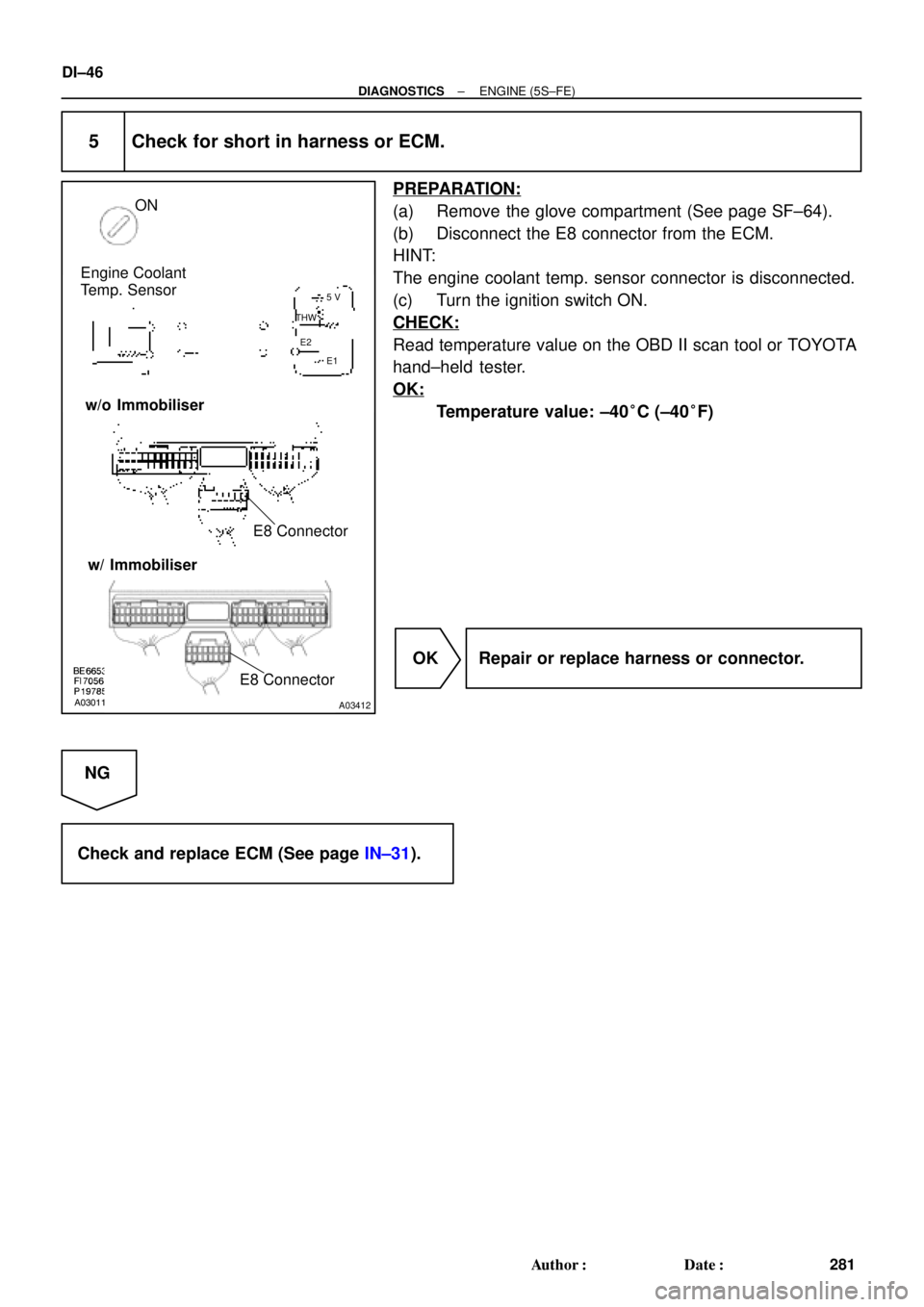
5 Check for short in harness or ECM.
PREPARATION:
(a) Remove the glove compartment (See page SF±64).
(b) Disconnect the E8 connector from the ECM.
HINT:
The engine coolant temp. sensor connector is disconnected.
(c) Turn the ignition switch ON.
CHECK:
Read temperature value on the OBD II scan tool or TOYOTA
hand±held tester.
OK:
Temperature value: ±40°C (±40°F)
OK Repair or replace harness or connector.
NG
Check and replace ECM (See page IN±31).
Page 1263 of 4592
FI7052
A00369
ON
VC (+)
± DIAGNOSTICSENGINE (5S±FE)
DI±51
286 Author�: Date�:
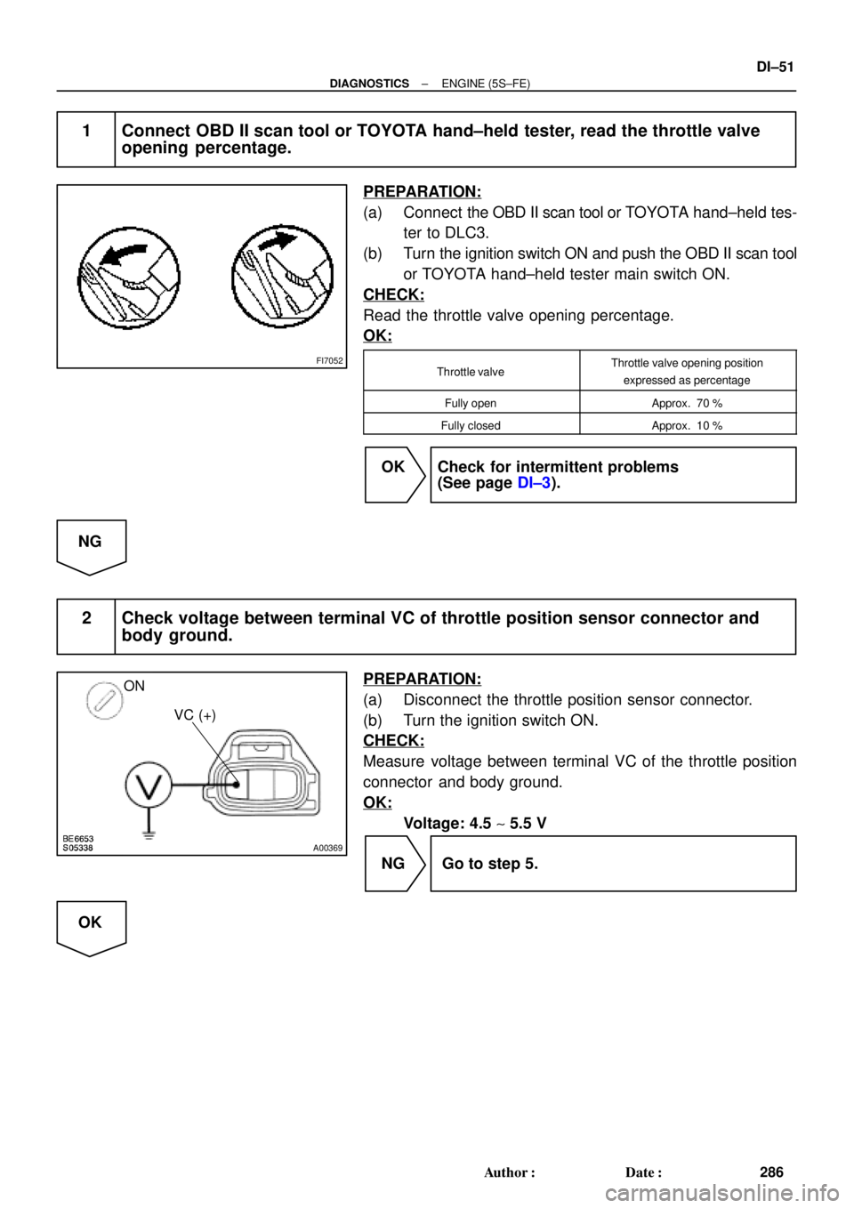
1 Connect OBD II scan tool or TOYOTA hand±held tester, read the throttle valve
opening percentage.
PREPARATION:
(a) Connect the OBD II scan tool or TOYOTA hand±held tes-
ter to DLC3.
(b) Turn the ignition switch ON and push the OBD II scan tool
or TOYOTA hand±held tester main switch ON.
CHECK:
Read the throttle valve opening percentage.
OK:
Throttle valveThrottle valve opening position
expressed as percentage
Fully openApprox. 70 %
Fully closedApprox. 10 %
OK Check for intermittent problems
(See page DI±3).
NG
2 Check voltage between terminal VC of throttle position sensor connector and
body ground.
PREPARATION:
(a) Disconnect the throttle position sensor connector.
(b) Turn the ignition switch ON.
CHECK:
Measure voltage between terminal VC of the throttle position
connector and body ground.
OK:
Voltage: 4.5 ~ 5.5 V
NG Go to step 5.
OK
Page 1264 of 4592
A03013A03413
ON
VTA
(+)E2
(±)
w/o Immobiliser
w/ Immobiliser
VTA
(+)E2
(±)
DI±52
± DIAGNOSTICSENGINE (5S±FE)
287 Author�: Date�:
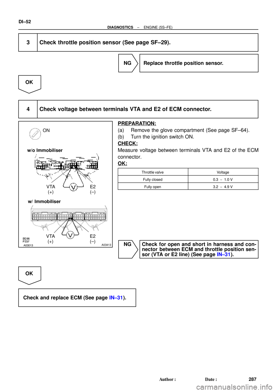
3 Check throttle position sensor (See page SF±29).
NG Replace throttle position sensor.
OK
4 Check voltage between terminals VTA and E2 of ECM connector.
PREPARATION:
(a) Remove the glove compartment (See page SF±64).
(b) Turn the ignition switch ON.
CHECK:
Measure voltage between terminals VTA and E2 of the ECM
connector.
OK:
Throttle valveVoltage
Fully closed0.3 ~ 1.0 V
Fully open3.2 ~ 4.9 V
NG Check for open and short in harness and con-
nector between ECM and throttle position sen-
sor (VTA or E2 line) (See page IN±31).
OK
Check and replace ECM (See page IN±31).
Page 1265 of 4592
A03008A03414
ON
VC
(+) E2
(±)
w/o Immobiliser
w/ Immobiliser
VC
(+) E2
(±)
± DIAGNOSTICSENGINE (5S±FE)
DI±53
288 Author�: Date�:
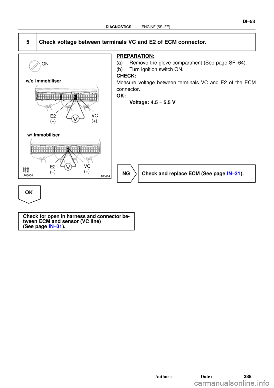
5 Check voltage between terminals VC and E2 of ECM connector.
PREPARATION:
(a) Remove the glove compartment (See page SF±64).
(b) Turn ignition switch ON.
CHECK:
Measure voltage between terminals VC and E2 of the ECM
connector.
OK:
Voltage: 4.5 ~ 5.5 V
NG Check and replace ECM (See page IN±31).
OK
Check for open in harness and connector be-
tween ECM and sensor (VC line)
(See page IN±31).
Page 1267 of 4592

Platinum
Electrode
Heater
Air±Fuel Ratio
(V)
2.6 4.0
3.8
3.6
3.4
3.2
3.0
2.8
2.4
12 13 14 15 16 17 18
Coatin")
A00477
Atmosphere
Cover
Exhaust GasPlatinum
Electrode
Solid Electrolyte
(Zirconia Element)
Platinum
Electrode
Heater
Air±Fuel Ratio
(V)
2.6 4.0
3.8
3.6
3.4
3.2
3.0
2.8
2.4
12 13 14 15 16 17 18
Coating (Ceramic)
ECM Monitored
A/F Sensor Voltage
19
± DIAGNOSTICSENGINE (5S±FE)
DI±55
290 Author�: Date�:
DTC P0125 Insufficient Coolant Temp. for Closed Loop
Fuel Control (Only for California Spec.)
CIRCUIT DESCRIPTION
To obtain a high purification rate for the CO, HC and NOx components of the exhaust gas, a three±way
catalytic converter is used, but for the most efficient use of the three±way catalytic converter, the air±fuel
ratio must be precisely controlled so that it is always close to the stoichiometric air±fuel ratio.
The A/F sensor has the characteristic that provides output voltage
* approximately proportional to the exist-
ing air±fuel ratio. The A/F sensor output voltage
* is used to provide feedback for the ECM to control the air±
fuel ratio.
By the A/F sensor output, the ECM can determine the deviation amount from the stoichiometric air±fuel ratio
and control the proper injection time immediately. If the A/F sensor is malfunctioning, ECM is unable to per-
form accurate air±fuel ratio control.
The A/F sensor is equipped with a heater which heats the zirconia element. The heater is controlled by the
ECM. When the intake air volume is low (the temp. of the exhaust gas is low), current flows to the heater
to heat the sensor for accurate oxygen concentration detection.
*: The voltage value changes at the inside of the ECM only.
DTC No.DTC Detecting ConditionTrouble Area
P0125
After engine is warmed up, A/F sensor output* does not
change when conditions (a), (b), and (c) continue for at least
1.5 min.:
*: Output value changes at inside of ECM only
(a) Engine speed: 1,500 rpm or more
(b) Vehicle speed: 40 ~ 100 km/h (25 ~ 62 mph)
(c) Throttle valve is not fully closed�Fuel system
�Injector
�Ignition system
�Gas leakage on exhaust system
�Open or short in A/F sensor circuit
�A/F sensor
�ECM
DI1JU±03
Page 1273 of 4592

Platinum Electrode
Heater
Coating (Ceramic)
Exhaust GasCoverIdeal Air±Fuel Mixture
Output Voltage
Richer")
P21242 FI7210
A00027
Atmosphere
Flange
Platinum Electrode
Solid Electrolyte
(Zirconia Element)
Platinum Electrode
Heater
Coating (Ceramic)
Exhaust GasCoverIdeal Air±Fuel Mixture
Output Voltage
Richer ± Air Fuel Ratio ± Leaner
± DIAGNOSTICSENGINE (5S±FE)
DI±61
296 Author�: Date�:
DTC P0125 Insufficient Coolant Temp. for Closed Loop
Fuel Control (Except California Spec.)
CIRCUIT DESCRIPTION
To obtain a high purification rate for the CO, HC and NOx components of the exhaust gas, a three±way
catalytic converter is used, but for the most efficient use of the three±way catalytic converter, the air±fuel
ratio must be precisely controlled so that it is always close to the stoichiometric air±fuel ratio.
The heated oxygen sensor has the characteristic where by its output voltage changes suddenly in the vicinity
of the stoichiometric air±fuel ratio. This is used to detect the oxygen concentration in the exhaust gas and
provide feedback to the computer for control of the air±fuel ratio.
When the air±fuel ratio becomes LEAN, the oxygen concentration in the exhaust increases and the heated
oxygen sensor informs the ECM of the LEAN condition (small electromotive force: 0 V).
When the air±fuel ratio is RICHER than the stoichiometric air±fuel ratio the oxygen concentration in the ex-
haust gas is reduced and the heated oxygen sensor informs the ECM of the RICH condition (large electromo-
tive force: 1 V).
The ECM judges by the electromotive force from the heated oxygen sensor whether the air±fuel ratio is RICH
or LEAN and controls the injection time accordingly. However, if malfunction of the heated oxygen sensor
causes output of abnormal electromotive force, the ECM is unable to perform accurate air±fuel ratio control.
The heated oxygen sensors include a heater which heats the zirconia element. The heater is controlled by
the ECM. When the intake air volume is low (the temperature of the exhaust gas is low) current flows to the
heater to heat the sensor for accurate oxygen concentration detection.
DTC No.DTC Detecting ConditionTrouble Area
P0125
After engine is warmed up, heated oxygen sensor (bank 1
sensor 1) output does not indicate RICH even once when
conditions (a), (b) and (c) continue for at least 1.5 min.:
(a) Engine speed: 1,500 rpm or more
(b) Vehicle speed: 40 ~ 100 km/h (25 ~ 62 mph)
(c) Throttle valve does not fully closed
�Fuel system
�Injector
�Ignition system
�Gas leakage on exhaust system
�Open or short in heated oxygen sensor (bank 1 sensor 1)
circuit
�Heated oxygen sensor (bank 1 sensor 1)
�ECM
DI00T±05
Page 1279 of 4592

Idling
IG SW OFF
(1)
1 ~ 3 min.1 min.Time
(2)(3)(4)
(5)
± DIAGNOSTICSENGINE (5S±FE)
DI±67
302 Author�: Date�:
CONFIRMATION DRIVING PATTERN
(1) Connec")
A01666
Vehicle speed
50 ~ 65 km/h
(31 ~ 40 mph)
Idling
IG SW OFF
(1)
1 ~ 3 min.1 min.Time
(2)(3)(4)
(5)
± DIAGNOSTICSENGINE (5S±FE)
DI±67
302 Author�: Date�:
CONFIRMATION DRIVING PATTERN
(1) Connect the TOYOTA hand±held tester to the DLC3.
(2) Switch the TOYOTA hand±held tester from normal mode to check mode (See page DI±3).
(3) Start the engine and warm it up with all accessory switches OFF.
(4) Drive the vehicle at 50 ~ 65 km/h (31 ~ 40 mph) for 1 ~ 3 min. to warm up the heated oxygen sensor.
(5) Let the engine idle for 1 min.
(6) Perform steps (3) to (5) three times.
HINT:
If a malfunction exists, the MIL will light up during step (6).
NOTICE:
If the conditions in this test are not strictly followed, detection of the malfunction will not be possible.
If you do not have a TOYOTA hand±held tester, turn the ignition switch OFF after performing steps
(3) to (6), then perform steps (3) to (6) again.
INSPECTION PROCEDURE
HINT:
Read freeze frame data using TOYOTA hand±held tester or OBD II scan tool. Because freeze frame records
the engine conditions when the malfunction is detected, when troubleshooting it is useful for determining
whether the vehicle was running or stopped, the engine warmed up or not, the air±fuel ratio lean or rich, etc.
at the time of the malfunction.
1 Are there any other codes (besides DTC P0130) being output?
YES Go to relevant DTC chart.
NO