Page 829 of 4592

I01475
25 Noise NOISE PRODUCED WHEN ENGINE STARTS
Whistling noise which becomes high±pitched when
accelerator strongly depressed, disappears shortly
after engine stops.Generator noise.
Whining noise occurs when A/C is operating. A/C noise.
Scratching noise occurs during sudden acceleration,
driving on rough roads or when ignition switch is turned
on.Fuel gauge noise.
Clicking sound heard when horn button is pressed,
then released. Whirring/ grating sound when pressed
continuously.Horn noise.
Murmuring sound stops when engine stops. Ignition noise.Ye s
No
No
No
No
NoYe s
Ye s
Ye s
Ye s
Tick±tock noise occurs in co±ordination with
blinking of flasher.
Noise occurs during window washer operation. Washer noise.Turn signal noise.
No
NoYe s
Ye s
Scratching noise occurs while engine is running
and continues for a while even after engine stops.
Scraping noise in time with wiper beat.Engine coolant temp. gauge noise.
Wiper noise.
Other type of noise.No
NoYe s
Ye s
± BODY ELECTRICALAUDIO SYSTEM
BE±113
2333 Author�: Date�:
Page 971 of 4592
BO0NH±01
H01346
BO±126
± BODYSEAT BELT PRETENSIONER
2474 Author�: Date�:
SEAT BELT PRETENSIONER
REMOVAL
NOTICE:
�If the wiring connector of the supplemental restraint
system is disconnected with the ignition switch at ON
or ACC, diagnostic trouble codes will be recorded.
�Never use SRS parts from another vehicle. When re-
placing parts, replace them with new parts.
1. REMOVE THESE PARTS:
(a) Front door scuff plate
(b) Center pillar lower garnish
2. REMOVE FRONT SEAT OUTER BELT
CAUTION:
Never disassemble the front seat outer belt.
NOTICE:
When removing the front outer seat belt, take care not to
pull the seat belt pretensioner wire harness.
(a) Remove the bolts and floor anchor.
(b) Using a screwdriver, remove the anchor caps.
HINT:
Tape the screwdriver tip before use.
(c) Remove the bolt and shoulder anchor.
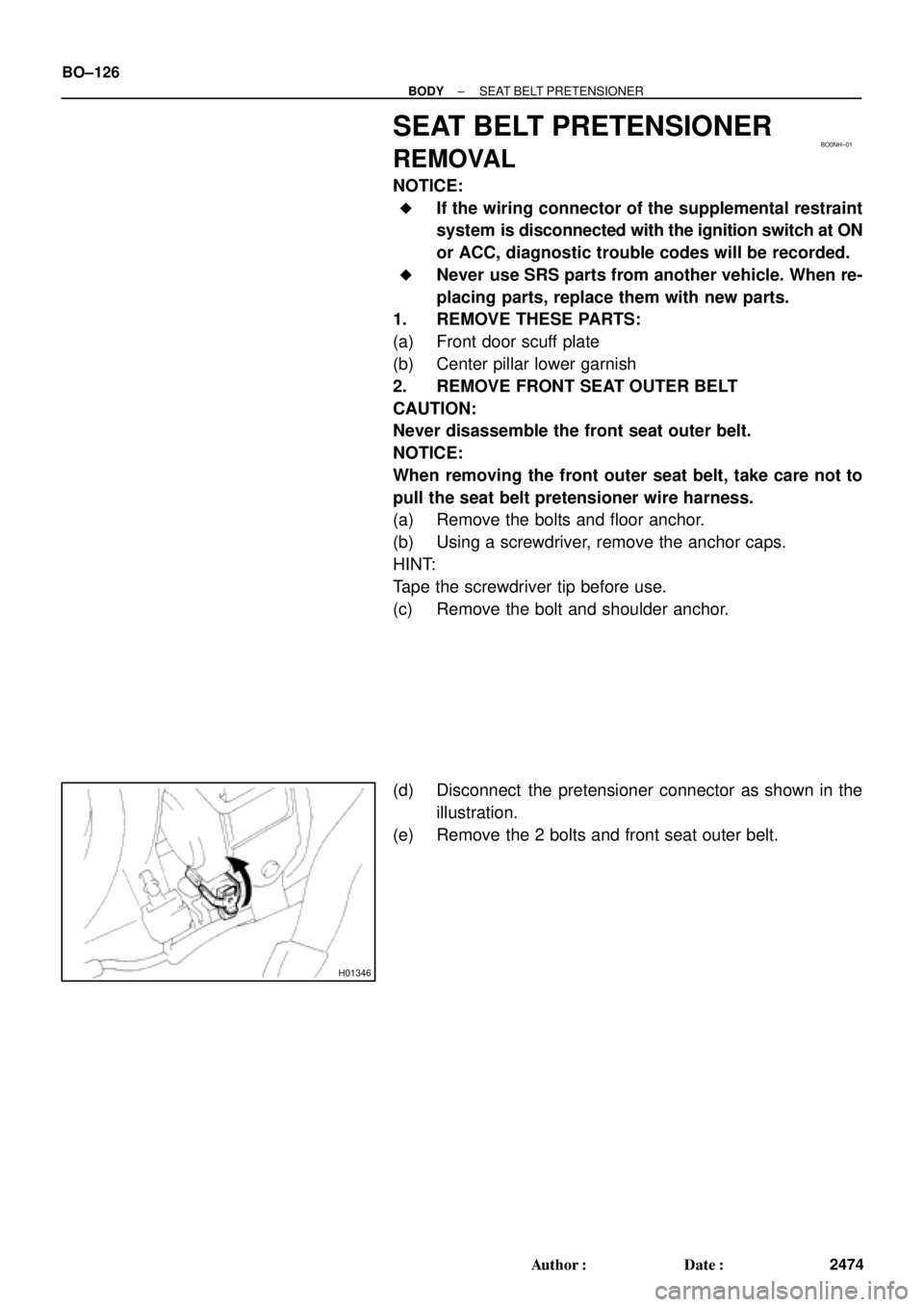
(d) Disconnect the pretensioner connector as shown in the
illustration.
(e) Remove the 2 bolts and front seat outer belt.
Page 984 of 4592

BE16U±01
I12031
Ignition
Switch
Fuel
Gauge
BatteryECM
I12029
Ignition
SwitchFuel Gauge
BatteryWire Harness Side
N20212
A
B
C
I12030
BatteryWarning Light
Ignition
Switch
Wire Harness Side
± BODY ELECTRICALCOMBINATION METER
BE±5
INSPECTION
1. INSPECT FUEL RECEIVER GAUGE OPERATION
(a) Disconnect the connector from the ECM.
(b) Turn the ignition switch ON, check that the receiver gauge
needle indicates EMPTY.
(c) Connect terminals 2 on the wire harness side connector
through a 3.4±W test bulb.
(d) Turn the ignition switch ON, check that the bulb lights up
and the receiver gauge needle moves towards the full
side.
HINT:
Because of the silicon oil in the gauge, it will take a short time
for needle to stabilize.
If operation is not as specified, inspect the receiver gauge resis-
tance.
2. INSPECT FUEL RECEIVER GAUGE RESISTANCE
Measure the resistance between terminals.
Tester connectionResistance (W)
A ± BApprox. 270.1
A ± CApprox. 141.3
B ± CApprox. 128.8
If resistance value is not as specified, replace the receiver
gauge.
3. INSPECT FUEL SENDER GAUGE RESISTANCE
(See page SF±36)
4. INSPECT FUEL LEVEL WARNING LIGHT
(a) Disconnect the connector from the sender gauge.
(b) Connect terminals 8 on the wire harness side connector.
(c) Turn the ignition switch ON, check that the warning light
lights up.
If the warning light does not light up, test the bulb or inspect wire
harness.
5. INSPECT FUEL LEVEL WARNING SWITCH
(See page SF±40)
Page 985 of 4592

N20216
C
B
A BE±6
± BODY")
N20215
Engine coolant temperature gauge
Ignition
Switch
BatterySender
Gauge
Z15788
Engine coolant temperature gauge
Ignition
Switch
BatteryWire Harness SideTest Bulb
(3.4 W)
N20216
C
B
A BE±6
± BODY ELECTRICALCOMBINATION METER
6. INSPECT ENGINE COOLANT TEMPERATURE RE-
CEIVER GAUGE OPERATION
(a) Disconnect the connector from the sender gauge.
(b) Turn the ignition switch ON and check that the receiver
gauge needle indicates COOL.
(c) Ground terminal on the wire harness side connector
through a 3.4±W test bulb.
(d) Turn the ignition switch ON, and check that the bulb lights
up and the receiver gauge needle moves to the hot side.
If operation is as specified, replace the sender gauge.
Then, recheck the system.
If operation is not as specified, measure the receiver gauge re-
sistance.
7. INSPECT ENGINE COOLANT TEMPERATURE RE-
CEIVER GAUGE RESISTANCE
Measure the resistance between terminals.
Tester connectionResistance (W) *
A ± BApprox. 175.7
A ± CApprox. 54.0
B ± CApprox. 229.7
*: This circuit includes the diode.
HINT:
Connect the test leads so that the current from the ohmmeter
can flow according to the above order.
If resistance value is not as specified, replace the receiver
gauge.
Page 986 of 4592

I07709
Slide
rheostat35.63 ±
0.1 W35.63 ±
0.1 W
Z14205
Warning Light
Ignition
Switch
Battery
1
N06640
± BODY ELECTRICALCOMBINATION METER
BE±7
8. INSPECT ENGINE COOLANT TEMPERATURE SEND-
ER GAUGE RESISTANCE
Connect the wire harness as shown in the illustration, and ad-
just the ammeter pointer to indicate º0º using the slide rheostat,
then read the rheostat indication.
Temperature °C (°F)Resistance (W)
50 (122.0)160 ± 240
120 (248.0)17.1 ± 21.2
If resistance value is not as specified, replace the engine cool-
ant temperature sender gauge.
9. INSPECT LOW OIL PRESSURE WARNING LIGHT
(a) Disconnect the connector from the warning switch and
ground terminal on the wire harness side connector.
(b) Turn the ignition switch ON and check that the warning
light lights up.
If the warning light does not light up, test the bulb.
10. INSPECT LOW OIL PRESSURE SWITCH
(a) Disconnect the connector from the switch.
(b) Check that continuity exists between terminal and ground
with the engine stopped.
(c) Check that no continuity exists between terminal and
ground with the engine running.
HINT:
Oil pressure should be over 24.5 kPa (0.25 kgf/cm
2, 3.55 psi).
If operation is not as specified, replace the switch.
Page 1087 of 4592
CHARGING SYSTEM
CH±1
1748 Author�: Date�:
CHARGING SYSTEM
ON±VEHICLE INSPECTION
CAUTI")
CH02U±01
Z11577
Except Maintenance±Free Battery
Z11556
Maintenance±Free Battery
Voltmeter
± CHARGING (5S±FE)CHARGING SYSTEM
CH±1
1748 Author�: Date�:
CHARGING SYSTEM
ON±VEHICLE INSPECTION
CAUTION:
�Check that the battery cables are connected to the
correct terminals.
�Disconnect the battery cables when the battery is giv-
en a quick charge.
�Do not perform tests with a high voltage insulation re-
sistance tester.
�Never disconnect the battery while the engine is run-
ning.
1. CHECK BATTERY ELECTROLYTE LEVEL
Check the electrolyte quantity of each cell.
Maintenance±Free Battery:
If under the lower level, replace the battery (or add distilled wa-
ter if possible). Check the charging system.
Except Maintenance±Free Battery:
If under the lower level, add distilled water.
2. Except Maintenance±Free Battery:
CHECK BATTERY SPECIFIC GRAVITY
Check the specific gravity of each cell.
Standard specific gravity:
1.25 ± 1.29 at 20°C (68°F)
If the specific gravity is less than specification, charge the bat-
tery.
3. Maintenance±Free Battery:
CHECK BATTERY VOLTAGE
(a) After having driven the vehicle and in the case that 20
minutes have not passed after having stopped the en-
gine, turn the ignition switch ON and turn on the electrical
system (headlight, blower motor, rear defogger etc.) for
60 seconds to remove the surface charge.
(b) Turn the ignition switch OFF and turn off the electrical sys-
tems.
(c) Measure the battery voltage between the negative (±)
and positive (+) terminals of the battery.
Standard voltage: 12.5 ± 12.9 V at 20°C (68°F)
If the voltage is less than specification, charge the battery.
Page 1089 of 4592
CHARGING SYSTEM
CH±3
1750 Author�: Date�: �
After installing a new belt, run the engine for about 5 min")
Z03473
BatteryVoltmeter
Generator Ammeter
Disconnect Wire
from Terminal B
B
± CHARGING (5S±FE)CHARGING SYSTEM
CH±3
1750 Author�: Date�: �
After installing a new belt, run the engine for about 5 min-
utes and recheck the belt tension.
6. VISUALLY CHECK GENERATOR WIRING AND
LISTEN FOR ABNORMAL NOISES
(a) Check that the wiring is in good condition.
(b) Check that there is no abnormal noise from the generator
while the engine is running.
7. CHECK CHARGE WARNING LIGHT CIRCUIT
(a) Warm up the engine and then turn it off.
(b) Turn off all accessories.
(c) Turn the ignition switch ºONº. Check that the charge warn-
ing light is lit.
(d) Start the engine. Check that the light goes off.
If the light does not go off as specified, troubleshoot the charge
light circuit.
8. INSPECT CHARGING CIRCUIT WITHOUT LOAD
HINT:
If a battery/generator tester is available, connect the tester to
the charging circuit as per manufacturer's instructions.
(a) If a tester is not available, connect a voltmeter and amme-
ter to the charging circuit as follows:
(1) Disconnect the wire from terminal B of the genera-
tor, and connect it to the negative (±) tester probe
of the ammeter.
(2) Connect the positive (+) tester probe of the amme-
ter to terminal B of the generator.
(3) Connect the positive (+) tester probe of the voltme-
ter to terminal B of the generator.
(4) Ground the negative (±) tester probe of the voltme-
ter.
(b) Check the charging circuit as follows:
With the engine running from idling to 2,000 rpm, check
the reading on the ammeter and voltmeter.
Standard amperage: 10 A or less
Standard voltage: 13.5 ± 15.1 V
If the voltmeter reading is more than standard voltage, replace
the voltage regulator.
Page 1103 of 4592
CHARGING SYSTEM
CH±1
1764 Author�: Date�:
CHARGING SYSTEM
ON±VEHICLE INSPECTION
CAUTI")
CH01D±01
Z11577
Except Maintenance±Free Battery
Z11556
Maintenance±Free BatteryVoltmeter
± CHARGING (1MZ±FE)CHARGING SYSTEM
CH±1
1764 Author�: Date�:
CHARGING SYSTEM
ON±VEHICLE INSPECTION
CAUTION:
�Check that the battery cables are connected to the
correct terminals.
�Disconnect the battery cables when the battery is
given a quick charge.
�Do not perform tests with a high voltage insulation
resistance tester.
�Never disconnect the battery while the engine is
running.
1. CHECK BATTERY ELECTROLYTE LEVEL
Check the electrolyte quantity of each cell.
(1) Maintenance±Free Battery:
If under the lower level, replace the battery (or add
distilled water if possible). Check the charging sys-
tem.
(2) Except Maintenance±Free Battery:
If under the lower level, add distilled water.
2. Except Maintenance±Free Battery:
CHECK BATTERY SPECIFIC GRAVITY
Check the specific gravity of each cell.
Standard specific gravity: 1.25 ± 1.29 at 20°C (68°F)
If the specific gravity is less than specification, charge the bat-
tery.
3. Maintenance±Free Battery:
CHECK BATTERY VOLTAGE
(a) After having driven the vehicle and in the case that 20
minutes have not passed after having stopped the en-
gine, turn the ignition switch ON and turn on the electrical
system (headlight, blower motor, rear defogger etc.) for
60 seconds to remove the surface charge.
(b) Turn the ignition switch OFF and turn off the electrical sys-
tems.
(c) Measure the battery voltage between the negative (±)
and positive (+) terminals of the battery.
Standard voltage: 12.5 ± 12.9 V at 20°C (68°F)
If the voltage is less than specification, charge the battery.