Page 750 of 4592
BE0AC±02
Z19047
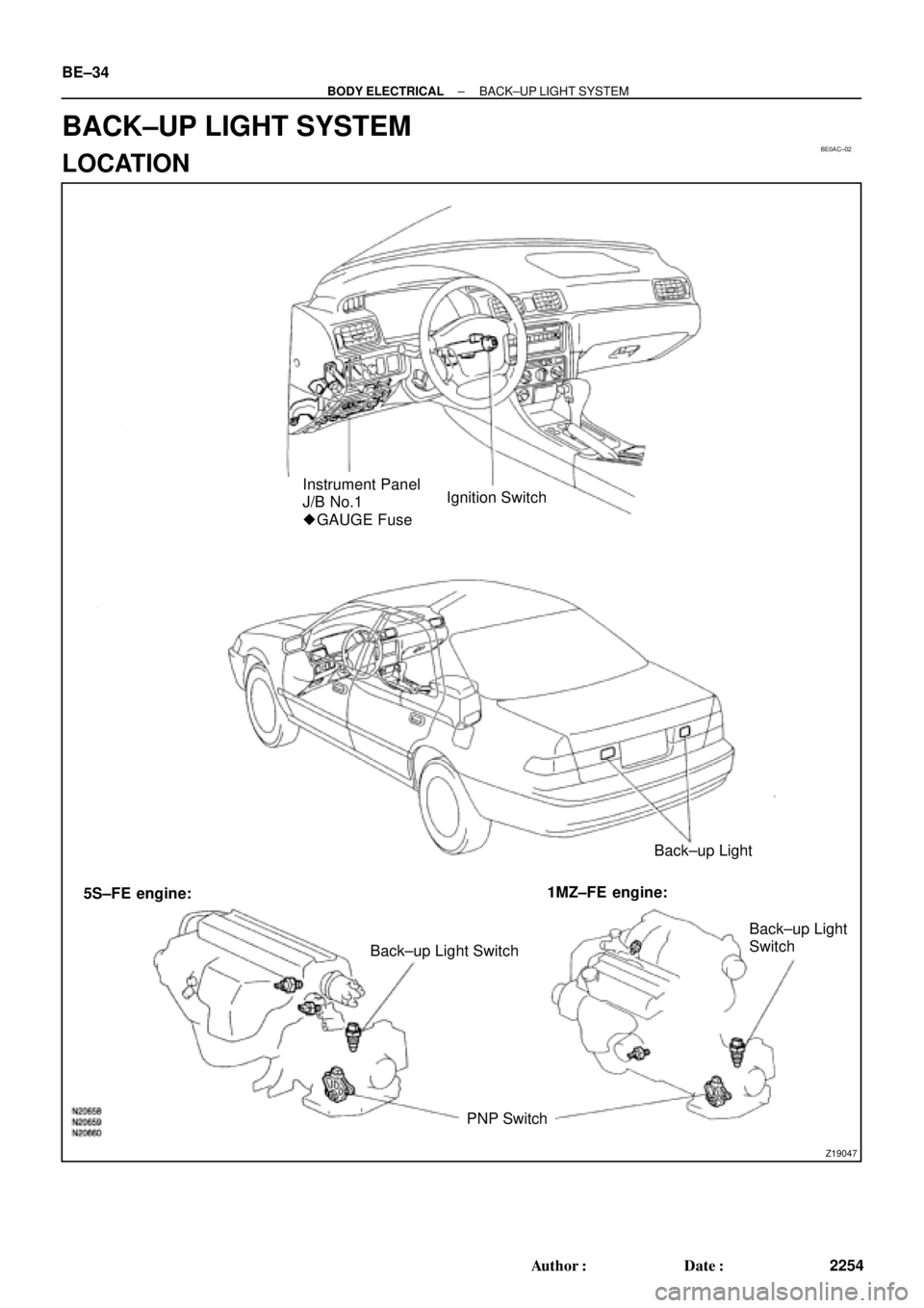
Instrument Panel
J/B No.1
� GAUGE FuseIgnition Switch
Back±up Light
Back±up Light SwitchBack±up Light
Switch
PNP Switch 5S±FE engine:1MZ±FE engine: BE±34
± BODY ELECTRICALBACK±UP LIGHT SYSTEM
2254 Author�: Date�:
BACK±UP LIGHT SYSTEM
LOCATION
Page 754 of 4592

N20209
Wire harness side:
1 2 3 4 5
6 7 8 9 10 11 12
e±12±2±B
BE±38
± BODY ELECTRICALSTOP LIGHT SYSTEM
2258 Author�: Date�:
4. INSPECT LIGHT FAILURE RELAY CIRCUIT
Disconnect the connector from the relay and inspect the con-
nector on the wire harness side, as shown.
Tester connectionConditionSpecified condition
1 ± GroundConstantContinuity*
2 ± GroundConstantContinuity*
9 ± GroundConstantContinuity*
11 ± GroundConstantContinuity
3 ± GroundLight control switch OFFNo voltage
3 ± GroundLight control switch TAIL or HEADBattery positive voltage
4 ± GroundIgnition switch LOCK or ACCNo voltage
4 ± GroundIgnition switch ONBattery positive voltage
7 ± GroundStop light switch OFFNo voltage
7 ± GroundStop light switch ONBattery positive voltage
8 ± GroundIgnition switch LOCK or ACCNo voltage
8 ± GroundIgnition switch ONBattery positive voltage
*: There is resistance because this circuit is grounded through
the bulb.
If the circuit is as specified, replace the relay.
If the circuit is not as specified, inspect the circuits connected
to other parts.
Page 764 of 4592
 Compare the")
N20160
Ignition
Switch
Fuel
Gauge
Battery
Z05727
Ignition
SwitchFuel
Gauge
Battery
Ie±5±1±A BE1206123
45
N20212
A
B
C BE±48
± BODY ELECTRICALCOMBINATION METER
2268 Author�: Date�:
(b) Compare the tester with tachometer indications.
DC 13.5 V 25°C at (77 °F)
Standard indicationAllowable range
700630 ± 770
1,000900 ± 1,100
2,0001,850 ± 2,150
3,0002,800 ± 3,200
4,0003,800 ± 4,200
5,0004,800 ± 5,200
6,0005,750 ± 6,250
7,0006,700 ± 7,300
4. INSPECT FUEL RECEIVER GAUGE OPERATION
(a) Disconnect the connector from the sender gauge.
(b) Turn the ignition switch ON, check that the receiver gauge
needle indicates EMPTY.
(c) Connect terminals 2 and 3 on the wire harness side con-
nector through a 3.4±W test bulb.
(d) Turn the ignition switch ON, check that the bulb lights up
and the receiver gauge needle moves towards the full
side.
HINT:
Because of the silicon oil in the gauge, it will take a short time
for needle to stabilize.
If operation is not as specified, inspect the receiver gauge resis-
tance.
5. INSPECT FUEL RECEIVER GAUGE RESISTANCE
Measure the resistance between terminals.
Tester connectionResistance (W)
A ± BApprox. 126.2
A ± CApprox. 280.5
B ± CApprox. 154.3
If resistance value is not as specified, replace the receiver
gauge.
Page 765 of 4592

N20161
F
1/2
E1
2 3
Z05730 1
3
42
5
BE1217 Ie±5±1±A
BatteryWarning Light
Ignition
Switch
N20213
1 3
N20214
1
3
N20215
Engine coolant temperature gauge
Ignition
Switch
BatterySender
Gauge
± BODY ELECTRICALCOMBINATION METER
BE±49
2269 Author�: Date�:
6. INSPECT FUEL SENDER GAUGE RESISTANCE
Measure the resistance between terminals 2 and 3 for each
float position.
Float position mm (in.)Resistance (W)
F: Approx. ±91.1 (±3.587)Approx. 3.0
1/2: Approx. ±34.2 (±1.346)Approx. 31.7
E: Approx. 30.8 (1.213)Approx. 110.0
If resistance value is not as specified, replace the sender
gauge.
7. INSPECT FUEL LEVEL WARNING LIGHT
(a) Disconnect the connector from the sender gauge.
(b) Connect terminals 1 and 3 on the wire harness side con-
nector.
(c) Turn the ignition switch ON, check that the warning light
lights up.
If the warning light does not light up, test the bulb or inspect wire
harness.
8. INSPECT FUEL LEVEL WARNING SWITCH
(a) Apply battery positive voltage between terminals 1 and 3
through a 3.4±W test bulb, check that the bulb lights up.
HINT:
It takes a short time for the bulb to light up.
(b) Submerge the switch in fuel, check that the bulb goes out.
If operation is not as specified, replace the sender gauge.
9. INSPECT ENGINE COOLANT TEMPERATURE RE-
CEIVER GAUGE OPERATION
(a) Disconnect the connector from the sender gauge.
(b) Turn the ignition switch ON and check that the receiver
gauge needle indicates COOL.
Page 766 of 4592

N20216
C
B
A
N21646
Z14205
Warning Light
Ignition
Switch
Battery
1 BE±50
± BODY ELECTRICALCOMBINATIO")
Z15788
Engine coolant temperature gauge
Ignition
Switch
BatteryWire Harness SideTest Bulb
(3.4 W)
N20216
C
B
A
N21646
Z14205
Warning Light
Ignition
Switch
Battery
1 BE±50
± BODY ELECTRICALCOMBINATION METER
2270 Author�: Date�:
(c) Ground terminal on the wire harness side connector
through a 3.4±W test bulb.
(d) Turn the ignition switch ON, and check that the bulb lights
up and the receiver gauge needle moves to the hot side.
If operation is as specified, replace the sender gauge.
Then, recheck the system.
If operation is not as specified, measure the receiver gauge re-
sistance.
10. INSPECT ENGINE COOLANT TEMPERATURE RE-
CEIVER GAUGE RESISTANCE
Measure the resistance between terminals.
Tester connectionResistance (W) *
A ± BApprox. 175.7
A ± CApprox. 54.0
B ± CApprox. 229.7
*: This circuit includes the diode.
HINT:
Connect the test leads so that the current from the ohmmeter
can flow according to the above order.
If resistance value is not as specified, replace the receiver
gauge.
11. INSPECT ENGINE COOLANT TEMPERATURE SEND-
ER GAUGE RESISTANCE
Measure the resistance between the terminal and gauge body.
Temperature °C (°F)Resistance (W)
50 (122.0)274
120 (248.0)26.4
If resistance value is not as specified, replace the engine cool-
ant temperature sender gauge.
12. INSPECT LOW OIL PRESSURE WARNING LIGHT
(a) Disconnect the connector from the warning switch and
ground terminal on the wire harness side connector.
(b) Turn the ignition switch ON and check that the warning
light lights up.
If the warning light does not light up, test the bulb.
Page 767 of 4592

N06640
BE1217
Warning Light
Ignition
Switch
Battery
N02346
OFF
ON
1 2
N01212
BE1217
Warning Light
Ignition
Switch
Battery
± BODY ELECTRICALCOMBINATION METER
BE±51
2271 Author�: Date�:
13. INSPECT LOW OIL PRESSURE SWITCH
(a) Disconnect the connector from the switch.
(b) Check that continuity exists between terminal and ground
with the engine stopped.
(c) Check that no continuity exists between terminal and
ground with the engine running.
HINT:
Oil pressure should be over 24.5 kPa (0.25 kgf/cm
2, 3.55 psi).
If operation is not as specified, replace the switch.
14. INSPECT BRAKE SYSTEM WARNING LIGHT
(a) Disconnect the connector from the brake fluid warning
switch.
(b) Release the parking brake pedal.
(c) Connect the terminals on the wire harness side of the lev-
el warning switch connector.
(d) Start the engine, check that the warning light lights up.
If the warning light does not light up, test the bulb or wire har-
ness.
15. INSPECT BRAKE FLUID LEVEL WARNING SWITCH
(a) Remove the reservoir tank cap and strainer.
(b) Disconnect the connector.
(c) Check that no continuity exists between the terminals with
the switch OFF (float up).
(d) Use syphon, etc. to take fluid out of the reservoir tank.
(e) Check that continuity exists between the terminals with
the switch ON (float down).
(f) Pour the fluid back in the reservoir tank.
If operation is not as specified, replace the switch.
16. INSPECT PARKING BRAKE SWITCH
(a) Check that continuity exists between the terminal and
switch body with the switch ON (switch pin released).
(b) Check that no continuity exists between the terminal and
switch body with the switch OFF (switch pin pushed in).
If operation is not as specified, replace the switch or inspect
ground point.
17. INSPECT WASHER FLUID LEVEL WARNING LIGHT
(a) Disconnect the connectors from the level warning switch
and parking brake switch.
(b) Connect terminals on the wire harness side connector of
the level warning switch connector.
(c) Remove the GAUGE fuse and turn the ignition switch ON,
and check that the warning light comes on.
If the warning light does not light up, test the bulb.
Page 768 of 4592

N20217
OFF
ONOhmmeter
Z05732
Warning Light
Ignition
Switch
Battery
1
BE0044
Warning Light
Ignition
Switch
Battery
Z16167
1
2 OFF
ON
N02354
1
2OFF
ON BE±52
± BODY ELECTRICALCOMBINATION METER
2272 Author�: Date�:
18. INSPECT WASHER FLUID LEVEL WARNING SWITCH
(a) Check that no continuity exists between terminals with the
switch OFF (float up).
(b) Check that continuity exists between terminals with the
switch ON (float down).
If operation is not as specified, replace the switch.
19. INSPECT OPEN DOOR WARNING LIGHT
Disconnect the connector from the door courtesy switch and
ground terminal 1 on the wire harness side, and check that the
warning light lights up.
If the warning light does not light up, inspect the bulb or wire har-
ness.
20. INSPECT SEAT BELT WARNING LIGHT
(a) Remove the integration relay from the instrument panel
junction block.
(b) Ground terminal 2 on the integration relay with the con-
nectors still connected.
(c) Turn the ignition switch ON and check that the warning
light lights up.
If the warning light does not light up, inspect the bulb or wire har-
ness.
21. w/o Power seat:
INSPECT BUCKLE SWITCH CONTINUITY
(a) Check that continuity exists between the terminals on the
switch side connector with the switch ON (belt fastened).
(b) Check that no continuity exists between the terminals on
the switch side connector with the switch OFF (belt unfas-
tened).
If operation is not as specified, replace the seat belt inner belt.
22. w/ Power seat:
INSPECT BUCKLE SWITCH CONTINUITY
(a) Check that continuity exists between terminals 1 and 2 on
the switch side connector with the switch ON (belt fas-
tened).
(b) Check that no continuity exists between terminals 1 and
2 on the switch side connector with the switch OFF (belt
unfastened).
If operation is not as specified, replace the seat belt inner belt.
Page 772 of 4592

BE0AM±03
N20315
Switch side:
1 2
3
4 5 6
N20314
ON3 4 5
Z08467
1
2
3456 Wire harness side:
S±6±1
N14863
1
2 35 12
35 BE±56
± BODY ELECTRICALDEFOGGER SYSTEM
2276 Author�: Date�:
INSPECTION
1. INSPECT DEFOGGER SWITCH CONTINUITY
Check that is continuity exists between terminals 2 and 6.
If continuity is not as specified, check the bulb.
2. INSPECT DEFOGGER TIMER OPERATION
(a) Connect the positive (+) lead from the battery to terminal
4 and the negative (±) lead to terminal 3.
(b) Connect the positive (+) lead from the battery to terminal
5 through a 3.4±W tester bulb.
(c) Push the defogger switch ON, check that the indicator
light and test bulb light up for 12 to 18 minutes, then the
indicator light and test bulb light goes out.
If operation is not as specified, replace the switch.
3. INSPECT DEFOGGER TIMER CIRCUIT
Disconnect the connector from the switch and inspect the con-
nector on the wire harness side, as shown in the table.
Tester connectionConditionSpecified condition
3 ± GroundConstantContinuity
4 ± GroundIgnition switch LOCK or ACCNo voltage
4 ± GroundIgnition switch ONBattery positive voltage
5 ± GroundIgnition switch LOCK or ACCNo voltage
5 ± GroundIgnition switch ONBattery positive voltage
±Connect terminals 3 and 5.Defogger system operation is normal
If the circuit is not as specified, replace the switch.
4. INSPECT DEFOGGER RELAY CONTINUITY
ConditionTester connectionSpecified condition
Constant1 ± 2Continuity
Apply B+ between
terminals 1 and 2.3 ± 5Continuity
If continuity is not as specified, replace the relay.