Page 773 of 4592

N21371
6
4
BE4029
Tester Probe
Tin FoilHeat Wire
BE0123
At Center
BE0124
0 VoltSeveral
Volts
Broken
Wire
± BODY ELECTRICALDEFOGGER SYSTEM
BE±57
2277 Author�: Date�:
5. w/ Heater:
INSPECT MIRROR DEFOGGER
(a) Connect the positive (+) lead from the battery to terminal
4 and the negative (±) lead to terminal 6.
(b) Check that the mirror becomes warm.
HINT:
It takes short time for the mirror to become warm.
6. INSPECT DEFOGGER WIRE
NOTICE:
�When cleaning the glass, use a soft, dry cloth, and
wipe the glass in the direction of the wire. Take care
not to damage the wires.
�Do not use detergents or glass cleaners with abrasive
ingredients.
�When measuring voltage, wind a piece of tin foil
around the top of the negative probe and press the foil
against the wire with your finger, as shown.
(a) Turn the ignition switch ON.
(b) Turn the defogger switch ON.
(c) Inspect the voltage at the center of each heat wire, as
shown.
VoltageCriteria
Approx. 5VOkay (No break in wire)
Approx.10V or 0VBroken wire
HINT:
If there is approximately 10 V, the wire is broken between the
center of the wire and the positive (+) end. If there is no voltage,
the wire is broken between the center of the wire and ground.
(d) Place the voltmeter positive (+) lead against the defogger
positive (+) terminal.
(e) Place the voltmeter negative (±) lead with the foil strip
against the heat wire at the positive (+) terminal end and
slide it toward the negative (±) terminal end.
(f) The point where the voltmeter deflects from zero to sever-
al V is the place where the heat wire is broken.
HINT:
If the heat wire is not broken, the voltmeter indicates 0 V at the
positive (+) end of the heat wire but gradually increases to about
12 V as the meter probe is moved to the other end.
Page 775 of 4592
BE0AN±03
Z19052
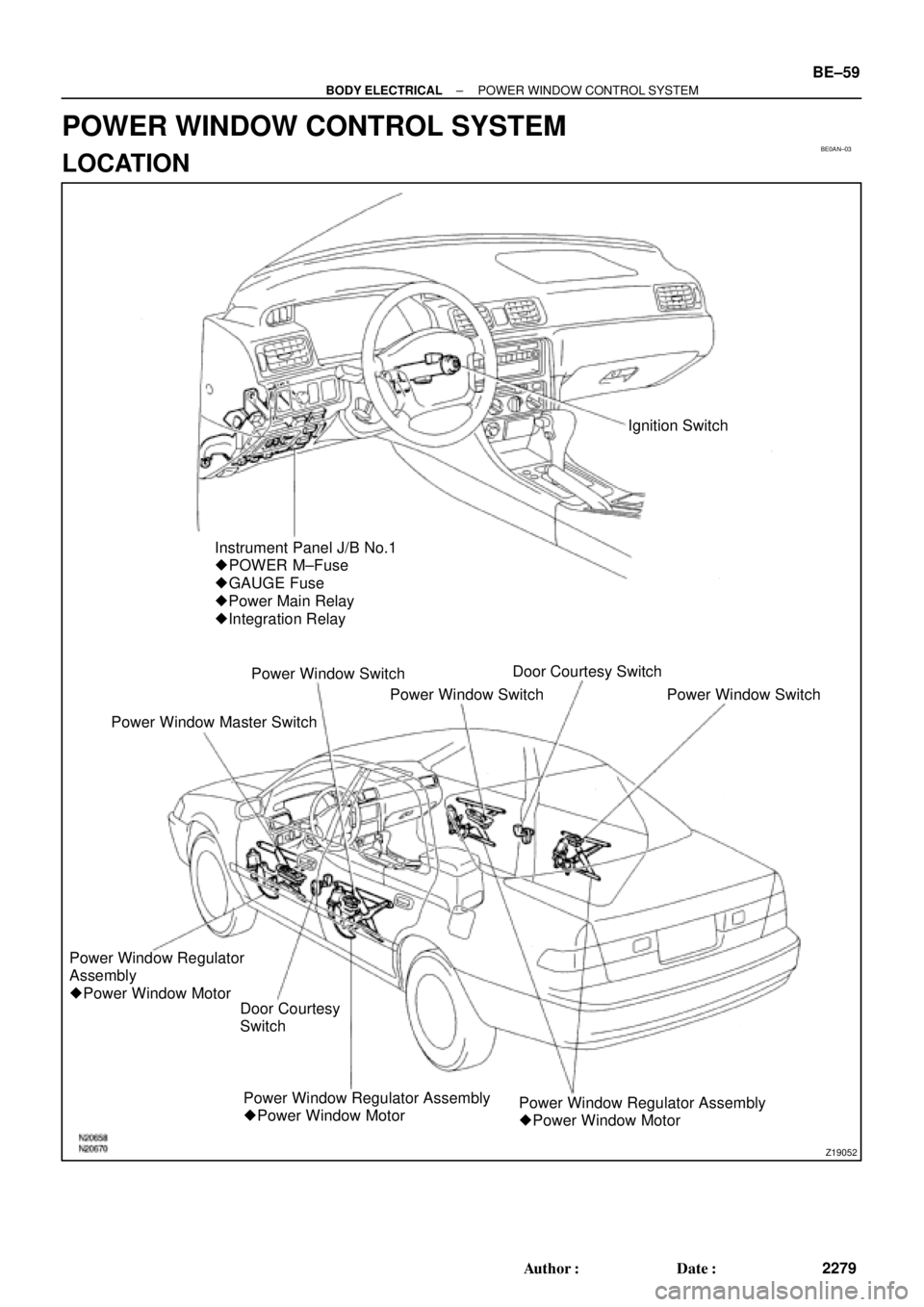
Ignition Switch
Instrument Panel J/B No.1
� POWER M±Fuse
� GAUGE Fuse
� Power Main Relay
� Integration Relay
Power Window Switch
Power Window Master SwitchPower Window SwitchDoor Courtesy Switch
Power Window Switch
Power Window Regulator
Assembly
� Power Window Motor
Door Courtesy
Switch
Power Window Regulator Assembly
� Power Window MotorPower Window Regulator Assembly
� Power Window Motor
± BODY ELECTRICALPOWER WINDOW CONTROL SYSTEM
BE±59
2279 Author�: Date�:
POWER WINDOW CONTROL SYSTEM
LOCATION
Page 778 of 4592

Z05738
3
6
Z05739
3
6
Z05740
8
Z05741
8 BE±62
± BODY ELECTRICALPOWER WINDOW CONTROL SYSTEM
2282 Author�: MH Date�: 3/7/02
3. Using an ammeter:
INSPECT ONE±TOUCH POWER WINDOW SYSTEM/
CURRENT OF CIRCUIT
(a) Disconnect the connector from the master switch.
(b) Connect the positive (+) lead from the ammeter to termi-
nal 3 on the wire harness side connector and the negative
(±) lead to negative terminal of the battery.
(c) Connect the positive (+) lead from the battery to terminal
6 on the wire harness side connector.
(d) As the window goes down, check that the current flow is
approximately 7 A.
(e) Check that the current increases up to approximately
14.5 A or more when the window stops going down.
HINT:
The circuit breaker opens some 4 ± 40 seconds after the win-
dow stops going down, so that check must be done before the
circuit breaker operates.
If the operation is as specified, replace the master switch.
4. Using an ammeter with a current ± measuring probe:
INSPECT ONE±TOUCH POWER WINDOW SYSTEM/
CURRENT OF CIRCUIT
(a) Remove the master switch with connector connected.
(b) Attach a current±measuring probe to terminal 8 of the
wire harness.
(c) Turn the ignition switch ON and set the power window
switch in the down position.
(d) As the window goes down, check that the current flow is
approximately 7 A.
(e) Check that the current increases up to approximately
14.5 A or more when the window stops going down.
HINT:
The circuit breaker opens some 4 ± 40 seconds after the win-
dow stops going down, so that check must be done before the
circuit breaker operates.
If operation is as specified, replace the master switch.
Page 779 of 4592

Z05742
123 456
7 8 9 10 11 121314 Wire harness side:
e±14±1±A
N20560
1 2 3 4 5
N20561
1 2 3 4 5
N14863
1235 12
35
± BODY ELECTRICALPOWER WINDOW CONTROL SYSTEM
BE±63
2283 Author�: Date�:
5. INSPECT POWER WINDOW MASTER SWITCH CIR-
CUIT
Disconnect the connector from the master switch and inspect
the connector on the wire harness side, as shown in the follow-
ing page.
Tester connectionConditionSpecified condition
4 ± GroundConstantContinuity
8 ± GroundIgnition switch position LOCK or ACC*No voltage
8 ± GroundIgnition switch position ONBattery positive voltage
*Exceptions: During 60 seconds after the ignition switch is
turned ON to OFF (ACC) or until driver or a passenger's door
is opened after the ignition switch is turned ON to OFF (ACC).
If the circuit is not as specified, inspect the circuits connected
to other parts.
6. Front passenger's door:
INSPECT POWER WINDOW SWITCH CONTINUITY
Switch positionTester connectionSpecified condition
UP1 ± 2, 3 ± 4Continuity
OFF1 ± 2, 3 ± 5Continuity
DOWN1 ± 4, 3 ± 5Continuity
If continuity is not as specified, replace the switch.
7. Rear door:
INSPECT POWER WINDOW SWITCH CONTINUITY
Switch positionTester connectionSpecified condition
UP1 ± 3, 4 ± 5Continuity
OFF1 ± 2, 4 ± 5Continuity
DOWN1 ± 2, 3 ± 5Continuity
If continuity is not as specified, replace the switch.
8. INSPECT POWER MAIN RELAY CONTINUITY
ConditionTester connectionSpecified condition
Constant1 ± 2Continuity
Apply B+ between
terminals 1 and 2.3 ± 5Continuity
If continuity is not as specified, replace the relay.
Page 783 of 4592
 Close(c) Open
A3 Type B:
± BODY ELECTRICALPOWER WINDOW CONTROL SYSTEM
BE±67
2287 Author�: Date�:
(f) Approximately 60 seconds later, connect the positive")
I21313
2
1
I12561
2
1
I12560
21
N20564
(b) Close(c) Open
A3 Type B:
± BODY ELECTRICALPOWER WINDOW CONTROL SYSTEM
BE±67
2287 Author�: Date�:
(f) Approximately 60 seconds later, connect the positive (+)
lead from the battery to terminal 1 and the negative (±)
lead to terminal 2, and check that the window begins to
descend.
If operation is not as specified, replace the motor.
13. Rear Door:
INSPECT POWER WINDOW MOTOR PTC THERM-
ISTOR OPERATION
(a) Disconnect the connector from the power window switch.
(b) Connect the positive (+) lead from the ammeter to termi-
nal 1 on the wire harness side connector and the negative
(±) lead to negative terminal of the battery.
(c) Connect the positive (+) lead from the battery to terminal
2 on the wire harness side connector, and raise the win-
dow to the fully position.
(d) Continue to apply voltage and check that the current
changes to less than 1 A within 4 to 90 seconds.
(e) Disconnect the leads from the terminals.
(f) Approximately 60 seconds later, connect the positive (+)
lead from the battery to terminal 2 and the negative (±)
lead to terminal 1, and check that the window begins to
descend.
If operation is not as specified, replace the motor.
14. Key±off power window signal:
INSPECT INTEGRATION RELAY (TYPE B) OPERA-
TION
HINT:
When the relay circuit is as specified, inspect the key±off power
window signal.
(a) Connect the positive (+) lead from the voltmeter to termi-
nal A3 and the negative (±) lead to body ground.
(b) Close the door with ignition switch turned to LOCK or
ACC, and check that the meter needle indicates battery
positive voltage.
(c) Open the door and check that the meter needle indicates
0 V.
Page 784 of 4592
 Close (c) Open
A12 Type C:
N20567
A12 Type C: BE±68
± BODY ELECTRICALPOWER WINDOW CONTROL SYSTEM
2288 Author�: MH Date�: 3/7/02
(d) Turn the ignition switch ON and check")
N20565
A3 Type B:
N20566
(b) Close (c) Open
A12 Type C:
N20567
A12 Type C: BE±68
± BODY ELECTRICALPOWER WINDOW CONTROL SYSTEM
2288 Author�: MH Date�: 3/7/02
(d) Turn the ignition switch ON and check that the meter
needle indicates battery positive voltage again.
If operation is not as specified, replace the relay.
15. Key±off power window signal:
INSPECT INTEGRATION RELAY (TYPE C) OPERA-
TION
HINT:
When the relay circuit is as specified, inspect the key±off power
window signal.
(a) Connect the positive (+) lead from the voltmeter to termi-
nal A12 and the negative (±) lead to body ground.
(b) Close the door with ignition switch turned to LOCK or
ACC, and check that the meter needle indicates battery
positive voltage.
(c) Open the door and check that the meter needle indicates
0 V.
(d) Turn the ignition switch ON and check that the meter
needle indicates battery positive voltage again.
If operation is not as specified, replace the relay.
16. INSPECT INTEGRATION RELAY CIRCUIT
(See page XX±XXX)
Page 789 of 4592
BE0AR±02
Z19490
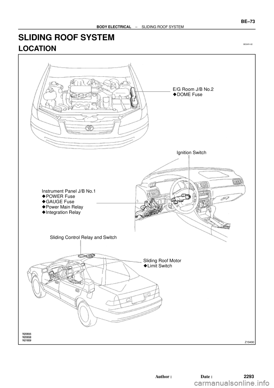
E/G Room J/B No.2
� DOME Fuse
Ignition Switch
Instrument Panel J/B No.1
� POWER Fuse
� GAUGE Fuse
� Power Main Relay
� Integration Relay
Sliding Control Relay and Switch
Sliding Roof Motor
� Limit Switch
± BODY ELECTRICALSLIDING ROOF SYSTEM
BE±73
2293 Author�: Date�:
SLIDING ROOF SYSTEM
LOCATION
Page 790 of 4592

BE0AS±02
N21643
Wire harness side:
12 3
4567 8
s±8±1
BE±74
± BODY ELECTRICALSLIDING ROOF SYSTEM
2294 Author�: Date�:
INSPECTION
1. INSPECT SLIDING ROOF CONTROL RELAY AND
SWITCH CIRCUIT
Disconnect the connector from the relay and switch and inspect
the connector on the wire harness side, as shown in the table.
TMMK made:
Tester connectionConditionSpecified condition
1 ± 5ConstantContinuity
2 ± GroundConstantContinuity
3 ± GroundLimit switch No.1 is OFF (Sliding roof is in a
closed position)No continuity
3 ± GroundLimit switch No.1 is ON (Sliding roof is in an open
position)Continuity
7 ± GroundLimit switch No.2 is OFF (Sliding roof is in a tilt
up position)No continuity
7 ± GroundLimit switch No.2 is ON (Sliding roof is in the
open position)Continuity
8 ± GroundLimit switch No.3 is OFF (Sliding roof is in a
closed position)No continuity
8 ± GroundLimit switch No.3 is ON (Sliding roof is in an open
position)Continuity
4 ± GroundIgnition switch is in a LOCK or ACC position* No voltage
4 ± GroundIgnition switch is in an ON positionBattery positive voltage
TMC made:
Tester connectionConditionSpecified condition
1 ± 5ConstantContinuity
2 ± GroundConstantContinuity
3 ± GroundNo.1 limit switch OFF (Sliding roof closed)No continuity
3 ± GroundNo.1 limit switch ON (Sliding roof opened)Continuity
7 ± GroundNo.2 limit switch OFF (Sliding roof tilted up open
approx. 200 mm (7.87 in.)No continuity
7 ± GroundNo.2 limit switch ON (Except for conditions
mentioned above)Continuity
4 ± GroundIgnition switch LOCK or ACC* No voltage
4 ± GroundIgnition switch ONBattery positive voltage
*: Exceptions: For 60 seconds after the ignition switch is turned
ON to OFF (ACC) or until driver or passenger door is opened
after the ignition switch is turned ON to OFF (ACC).
If the circuit is not as specified, replace the relay and switch.