Page 1375 of 4592

DI±163
398 Author�: Date�:
DTC P1300 Igniter Circuit Malfunction No.1
DTC P1310 Igniter Circuit Malfunction No.2
CIRCUIT DESCRIPTION
The ECM determines the ignition timi")
± DIAGNOSTICSENGINE (5S±FE)
DI±163
398 Author�: Date�:
DTC P1300 Igniter Circuit Malfunction No.1
DTC P1310 Igniter Circuit Malfunction No.2
CIRCUIT DESCRIPTION
The ECM determines the ignition timing, turns on Tr1 at a predetermined angle (°CA) before the desired
ignition timing and outputs and ignition signal (IGT) 1 to the igniter.
Since the width of the IGT signal is constant, the dwell angle control circuit in the igniter determines the time
the control circuit starts primary current flow to the ignition coil based on the engine rpm and ignition timing
one revolution ago, that is, the time the Tr2 turns on.
When it reaches the ignition timing, the ECM turns Tr1 off and outputs the IGT signal O.
This turns Tr2 off, interrupting the primary current flow and generating a high voltage in the secondary coil
which causes the spark plug to spark. Also, by the counter electromotive force generated when the primary
current is interrupted, the igniter sends an ignition confirmation signal (IGF) to the ECM. The ECM stops fuel
injection as a fail safe function when the IGF signal is not input to the ECM.
DTC No.DTC Detecting ConditionTrouble Area
P1300No IGF signal to ECM for 4 consecutive IGT1 signals during
engine running�Open or short in IGF or IGT circuit from igniter to ECM
�Ignition coil No.1 (Igniter No.1)
�ECM
P1310No IGF signal to ECM for 4 consecutive IGT2 signals during
engine running�Open or short in IGF or IGT circuit from igniter to ECM
�Ignition coil No.2 (Igniter No.2)
�ECM
HINT:
Ignition coil No.1 is for cylinder No.1 and No.4, and ignition coil No.2 is for cylinder No.2 and No.3.
DI01G±06
Page 1376 of 4592

A07122
IG Switch
B±R
BatteryEngine Room
J/B No.2
76B±R13
1II3B±R
B
BR
Spark Plug
Spark Plug
2
3 2
3 4
Tr2 Igniter
No.1
Ignition
Coil
No.1
FL Block
Y±R
BR
B
20
19
IGT2
Tr1
E9
E9
E9
W±R
IGT1
IGF5 V
Tr1
Ignition Coil
No.2
Igniter
No.2
AA A
EC
Tr2
W±R
B±R 5 51B 1K
Instrument
W±R
W±R
2L 2A
4 1
AM2B
F4 F6 1
1
B±G
MAIN FL
3 1
4
J/C J25
*1: w/o Immobiliser
*2: w/ Immobiliser(*1) (*2)
ECM
E9 23
E9 22
E9 17
(*1) (*2)
W±R
Panel J/BB
B
BR
BR J19
J/C
DI±164
± DIAGNOSTICSENGINE (5S±FE)
399 Author�: Date�:
WIRING DIAGRAM
INSPECTION PROCEDURE
HINT:
�If DTC P1300 is displayed, check ignition coil No.1 circuit.
�If DTC P1300 is displayed, check ignition coil No.2 circuit.
�Read freeze frame data using TOYOTA hand±held tester or OBD II scan tool. Because freeze frame
records the engine conditions when the malfunction is detected, when troubleshooting it is useful for
determining whether the vehicle was running or stopped, the engine warmed up or not, the air±fuel
ratio lean or rich, etc. at the time of the malfunction.
1 Check for spark plug and spark of misifining cylinder (See page DI±89).
NG Go to step 4.
OK
2 Check for open and short in harness and connector in IGF signal circuit between
ECM and ignition coils (See page IN±31).
NG Repair or replace harness or connector.
OK
Page 1377 of 4592
A03023A00417A03427
ON
IGF
(+)
w/o Immobiliser
w/ Immobiliser
IGF
(+)
± DIAGNOSTICSENGINE (5S±FE)
DI±165
400 Author�: Date�:
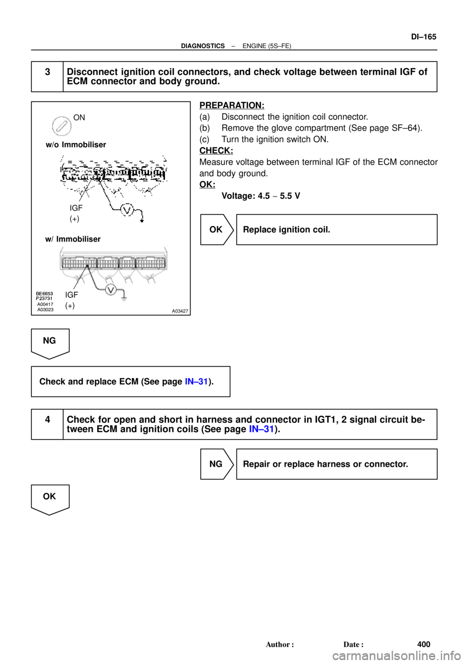
3 Disconnect ignition coil connectors, and check voltage between terminal IGF of
ECM connector and body ground.
PREPARATION:
(a) Disconnect the ignition coil connector.
(b) Remove the glove compartment (See page SF±64).
(c) Turn the ignition switch ON.
CHECK:
Measure voltage between terminal IGF of the ECM connector
and body ground.
OK:
Voltage: 4.5 ~ 5.5 V
OK Replace ignition coil.
NG
Check and replace ECM (See page IN±31).
4 Check for open and short in harness and connector in IGT1, 2 signal circuit be-
tween ECM and ignition coils (See page IN±31).
NG Repair or replace harness or connector.
OK
Page 1379 of 4592
A03024A03428
START
IGT2 (+)
IGT1 (+)
w/o Immobiliser
w/ Immobiliser
IGT2 (+)
IGT1 (+)
BE6653A01761A01861
ON
START
1 (+)
± DIAGNOSTICSENGINE (5S±FE)
DI±167
402 Author�: Date�:
6 Disconnect ignition coil connectors, and check voltage between terminals IGT1,
2 of ECM connector and body ground.
PREPARATION:
(a) Disconnect the ignition coil connectors.
(b) Remove the glove compartment (See page SF±64).
CHECK:
Measure voltage between terminals IGT1, 2 of the ECM con-
nector and body ground when the engine is cranked.
OK:
Voltage: More than 0.1 V and less than 5 V
OK Replace ignition coil.
NG
7 Check ignition coil with igniter power source circuit.
PREPARATION:
Disconnect the ignition coil connector.
CHECK:
Measure voltage between terminal 1 of the ignition coil with the
igniter connector and body ground when the ignition switch is
turned to ON and STA position.
OK:
Voltage: 9 ~ 14 V
NG Repair ignition coil with igniter power source
circuit.
OK
Page 1380 of 4592
DI±168
± DIAGNOSTICSENGINE (5S±FE)
403 Author�: Date�:
8 Check for open and short in harness and connector between ignition switch and
ignition coils (See page IN±31).
NG Repair or replace harness or connector.
OK
9 Check ignition coil (See page IG±5).
NG Replace ignition coil.
OK
10 Check EFI main relay (Marking: EFI) (See page SF±40).
NG Replace EFI main relay.
OK
Replace igniter.
Page 1384 of 4592
A03025A03429
Brake Pedal
Depressed
ON ON
STP (+) Brake Pedal
Released
w/o Immobiliser
w/ Immobiliser
STP (+)
DI±172
± DIAGNOSTICSENGINE (5S±FE)
407 Author�: Date�:
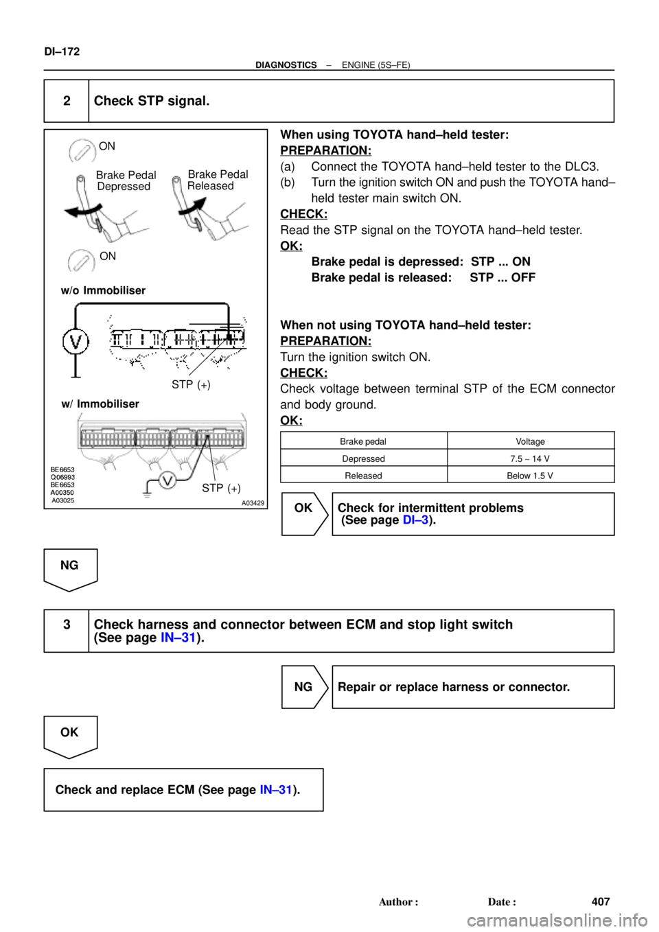
2 Check STP signal.
When using TOYOTA hand±held tester:
PREPARATION:
(a) Connect the TOYOTA hand±held tester to the DLC3.
(b) Turn the ignition switch ON and push the TOYOTA hand±
held tester main switch ON.
CHECK:
Read the STP signal on the TOYOTA hand±held tester.
OK:
Brake pedal is depressed: STP ... ON
Brake pedal is released: STP ... OFF
When not using TOYOTA hand±held tester:
PREPARATION:
Turn the ignition switch ON.
CHECK:
Check voltage between terminal STP of the ECM connector
and body ground.
OK:
Brake pedalVoltage
Depressed7.5 ~ 14 V
ReleasedBelow 1.5 V
OK Check for intermittent problems
(See page DI±3).
NG
3 Check harness and connector between ECM and stop light switch
(See page IN±31).
NG Repair or replace harness or connector.
OK
Check and replace ECM (See page IN±31).
Page 1385 of 4592

(*2)
E72
± DIAGNOSTICSENGINE (5S±FE)
DI±173
408 Author�: Da")
A03605
Engine Room J/B No.2
EFI11
B
Battery B±G11
2A E7ECM
F4BATT
2JB±Y
F68
FL Block
MAIN FL
*1: w/o Immobiliser
*2: w/ Immobiliser(*1)
(*2)
E72
± DIAGNOSTICSENGINE (5S±FE)
DI±173
408 Author�: Date�:
DTC P1600 ECM BATT Malfunction
CIRCUIT DESCRIPTION
Battery positive voltage is supplied to terminal BATT of the ECM even when the ignition switch is OFF for
use by the DTC memory and air±fuel ratio adaptive control value memory, etc.
DTC No.DTC Detecting ConditionTrouble Area
P1600Open in back up power source circuit�Open in back up power source circuit
�ECM
HINT:
If DTC P1600 appear, the ECM does not store another DTC.
WIRING DIAGRAM
INSPECTION PROCEDURE
HINT:
Read freeze frame data using TOYOTA hand±held tester or OBD II scan tool. Because freeze frame records
the engine conditions when the malfunction is detected, when troubleshooting it is useful for determining
whether the vehicle was running or stopped, the engine warmed up or not, the air±fuel ratio lean or rich, etc.
at the time of the malfunction.
DI01I±10
Page 1389 of 4592
± DIAGNOSTICSENGINE (5S±FE)
DI±177
412 Author�: Date�:
INSPECTION PROCEDURE
HINT:
This diagnostic chart is based on the premise that the engine is cranked normally. If the engine is not
cranked, proceed to the problem symptoms table on page DI±28.
TOYOTA hand±held tester:
1 Connect TOYOTA hand±held tester, and check STA signal.
PREPARATION:
(a) Connect the TOYOTA hand±held tester to the DLC3.
(b) Turn the ignition switch ON and push the TOYOTA hand±held tester main switch ON.
CHECK:
Read STA signal on the TOYOTA hand±held tester while the starter operates.
OK:
Ignition Switch PositionONSTART
STA signalOFFON
OK Proceed to next circuit inspection shown on
problem symptoms table (See page DI±28).
NG
2 Check for open in harness and connector between ECM and starter relay
(Marking: ST) (See page IN±31).
NG Repair or replace harness or connector.
OK
Check and replace ECM (See page IN±31).